
You are using an out of date browser. It may not display this or other websites correctly.
You should upgrade or use an alternative browser.
You should upgrade or use an alternative browser.
The Geneva .... My first Hit and Miss Engine
- Thread starter bearcar1
- Start date


Help Support Home Model Engine Machinist Forum:
This site may earn a commission from merchant affiliate
links, including eBay, Amazon, and others.
Thanks Zeep, I will use the utmost care in making my selection of suitable replacements :big:zeeprogrammer said:Wow. That's looking great Jim.
As for getting rid of the crappy nuts..."Choose wisely".
Maryak said:Jim,
Terrific, and a very clever setup. :bow:
Best Regards
Bob
Thanks Bob, I had given thought to setting it all up on the cross slide of the lathe as I have seen done in the past but could not bring myself to do it that way for fear of messing up. This way pretty much assured my success in getting/keeping everything in good order.
ozzie46 said:Nice work, very creative. :bow: :bow:
Ron
Thank you Ron
Deanofid said:Nice work holding write up, Jim!
Good use of the dowel pins to keep things lined up, too.
Dean
Thanks also Dean. I scratched my *ahem* head for a bit to finally arrive at this set up. The dowel pins were a carry over from my Grandfather, he used dowel pins to keep assemblies lined up when he was doing machine work and I figured it would be of benefit in this instance as well. As far as the write up, I just hope that by demonstrating the methods I used it may be of help to others, lord knows I have picked up ideas and tricks from members such as yourself here at HMEM.
BC1
Jim
Next up in this adventure series was the making of the cylinder head and I began by first turning out the blank that was to become the head from some round stock. The spigot shown below is a nice sliding fit to the bore of the cylinder block and will be used to assist in alignment purposes later on. But first some holes need to be carefully located, For this I used a spin indexer with the piece held in a 5C backed 3 jaw chuck. I use this same setup quite a bit and it has served me quite admirably for many years. One of these days I will break down and pop for a DRO but until that time arrives I'll use my proven methods. I was thinking of doing a separate thread outlining the steps that I used in order to illustrate to some of those that have never used a spin indexer before how it is done and will do so if enough interest is shown but for now I'l just paint some pretty broad strokes to save time. :bow:


The hole locations consist of two concentric bolt circles, one consisting of six holes for the clamping studs and the other has three positions marked out at 120* from each other that will become the valve locations and the spark plug hole. When doing the layout, the centerline of the valve ports have to be extended onto the side of the head as this will be the positions for the intake manifold and exhaust pipe.


After laying out all of the locations I placed the blank in a holding jig made from a scrap of hard maple block I had on hand, this made it easy to use my trusty, rather quaint, method of center popping. ( easy there Dean, you still may not have my hammer but you are more than welcome to borrow it ;D )


And finally, drilling the holes for the clamping studs.

Now for the valve ports, this was a bit more complicated, not really, but definitely more time consuming. With the part held in the four jaw lathe chuck it was centered using the dial indicator and wiggler method, (same set up and procedure used for locating the cylinder bore). I used a .250" carbide end mil cutter to cut the intake and exhaust ports. these holes do not go completely through the head but are a flat bottomed blind hole that intersects the holes for the intake and exhaust manifolds. After each port was cut, a #12 drill followed by a .187" reamer was used to extend the passages through the head. The small bit of tape is a reminder to me. That hole will be for the spark plug and will be treated to a different size and tapped later.


After indicting and drilling the spark plug hole the part was taken to the mill where it was held in the vice to drill the two manifold ports. I used two drill bits in the stud holes to get the proper 90* orientation and once again used the DI and wiggler to find the center, after which a .250" end mill was used to cut these passages. After all of the dust had settled, there is the partially finished head to date.


So far, so good. I hope you all have enjoyed the ride thus far.
Kind regards
BC1
Jim
The hole locations consist of two concentric bolt circles, one consisting of six holes for the clamping studs and the other has three positions marked out at 120* from each other that will become the valve locations and the spark plug hole. When doing the layout, the centerline of the valve ports have to be extended onto the side of the head as this will be the positions for the intake manifold and exhaust pipe.
After laying out all of the locations I placed the blank in a holding jig made from a scrap of hard maple block I had on hand, this made it easy to use my trusty, rather quaint, method of center popping. ( easy there Dean, you still may not have my hammer but you are more than welcome to borrow it ;D )
And finally, drilling the holes for the clamping studs.
Now for the valve ports, this was a bit more complicated, not really, but definitely more time consuming. With the part held in the four jaw lathe chuck it was centered using the dial indicator and wiggler method, (same set up and procedure used for locating the cylinder bore). I used a .250" carbide end mil cutter to cut the intake and exhaust ports. these holes do not go completely through the head but are a flat bottomed blind hole that intersects the holes for the intake and exhaust manifolds. After each port was cut, a #12 drill followed by a .187" reamer was used to extend the passages through the head. The small bit of tape is a reminder to me. That hole will be for the spark plug and will be treated to a different size and tapped later.
After indicting and drilling the spark plug hole the part was taken to the mill where it was held in the vice to drill the two manifold ports. I used two drill bits in the stud holes to get the proper 90* orientation and once again used the DI and wiggler to find the center, after which a .250" end mill was used to cut these passages. After all of the dust had settled, there is the partially finished head to date.
So far, so good. I hope you all have enjoyed the ride thus far.
Kind regards
BC1
Jim
I was in the right mood finally to get into the shop and do some work on this engine. A couple of 'in-between' projects that my friend wanted me to do (like 8 repo wheels for his 1920's American Flyer locos) man was that a PIMA but they got done and we pressed them on the axles over the weekend. Anyway, back to Geneva. The next step I thought should be the valve guides as they appeared to be an easy apprentice exercise on the lathe. I pulled a .375" bronze welding rod from the drawer and proceeded to cut it down to final diameter. once this was done it was a simple matter of turning a spigot on the end that would be a press fit into the cylinder head. I used a #00 center drill to just 'dimple' the end. This dimple would be used later to locate the center of the guide when it gets drilled, reamed and the valve seat cut. (whew, I'm not looking forward to all of that) Then it was parted off a bit over length and put aside until its brother was worked on. With both of the guides finished on the one end they were then placed in a collet using the small spigot to close down on and then the smaller tip that would become the spring seat was turned down and the piece faced to final length. I used the micrometer stop for these steps. I like using it as I can set it and forget it when making final cuts that require the precision. Enough for the day as I am tired and need to take a break for a while.


BC1
Jim
BC1
Jim

$39.99
$49.99
Sunnytech Low Temperature Stirling Engine Motor Steam Heat Education Model Toy Kit For mechanical skills (LT001)
stirlingtechonline


$45.99
Sunnytech Mini Hot Air Stirling Engine Motor Model Educational Toy Kits Electricity HA001
stirlingtechonline


$94.99
$109.99
AHS Woodmaster 4400 Maintenance Kit for Outdoor Wood Boiler Treatment
Alternative Heating & Supplies


$12.56
$39.95
Complete Plans for Building Horse Barns Big and Small(3rd Edition)
ThriftBooks-Atlanta


$99.99
AHS Outdoor Wood Boiler Yearly Maintenance Kit with Water Treatment - ProTech 300 & Test Kit
Alternative Heating & Supplies


$24.99
$27.99
HOZLY 5PCS/Lot ISO30 Tool Holder Clamp Flame Proof Rubber Claw CNC Machines Automatic Tool Changer
HOZLY


$24.99
$34.99
Bowl Sander Tool Kit w/Dual Bearing Head & Hardwood Handle | 42PC Wood Sander Set | 2" Hook & Loop Sanding Disc Sandpaper Assortment | 1/4" Mandrel Bowl Sander for Woodturning | Wood Lathe Tools
Peachtree Woodworking Supply Inc


![DreamPlan Home Design and Landscaping Software Free for Windows [PC Download]](https://m.media-amazon.com/images/I/51kvZH2dVLL._SL500_.jpg)
$0.00
DreamPlan Home Design and Landscaping Software Free for Windows [PC Download]
Amazon.com Services LLC

$519.19
$699.00
FoxAlien Masuter Pro CNC Router Machine, Upgraded 3-Axis Engraving All-Metal Milling Machine for Wood Acrylic MDF Nylon Carving Cutting
FoxAlien Official


$40.02
$49.99
Becker CAD 12 3D - professional CAD software for 2D + 3D design and modelling - for 3 PCs - 100% compatible with AutoCAD
momox Shop


$89.99
Outdoor Wood Boiler Water Treatment Rust Inhibitor- AmTech 300 & Test Kit
Alternative Heating & Supplies


Hi Kevin, it's funny you should bring that up. The drawings do not call for any seats but I am considering installing something for that purpose. However, with no more usage than this engine will likely ever see, I doubt that they will be needed. Anyone else have thoughts on the subject?
BC1
Jim
BC1
Jim
Hi Jim,
I have no seats on my Coles H&M and no plans to put them in the Whittle, There's just a 45deg face cut into the Alum. Your right these engines will never see any work and not run for hours on end. On the radial the seat and guide are all one piece put in from the chamber then a special round nut holds it in from the top.
Well unless you plan on running it for hours on end instead of starting a new build :big:
Tony
Coming along well, Jim.
I think you will do fine with just the guide material as seats, too. May not be the preferred way, but can still be a proper way. My vertical has the valves in a pocket, and the pocket assembly is made from aluminum. I cut the seats right into the pocket assembly and have never had any trouble. That engine has about 10 hours on it.
Pocket, guides, and seats, all made in the same material.
Dean
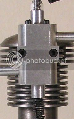
Tony and Dean, thank you for weighing in on the subject of valve seats vs. plain head. I had *ahem*, 'thought' ??? about perhaps making up some chambered/cups as was mentioned or pressing in a smallish cast iron ring of some sort in the fashion of full scale practice, but have settled upon not installing anything and rely on the head itself to suffice. D. Kerzel seems to have done a pretty good job of this design so far so I can not imagine that he would have overlooked such a critical area otherwise. Now I just have to be extra careful when I cut the valve seats, this will be discussed later when the time comes. I 'puttered' around in the shop just a bit and decided to drill and tap the holes in the cylinder block for the head mounting studs. I carefully located the center on the bore and very lightly scribed a line at the 12 o'clock and 6 o'clock positions. Then I placed the head on the block using that short spigot that was mentioned previously to center the head to the bore and aligned the holes in the head over the scribed lines and held it all in place on a tooling plate with a short section of threaded rod screwed into it and through the hole for the spark plug, tightening it all down with a washer and nut. (sorry I did not get pictures of that  ) Then I 'just' did begin to drill the hole positions with the clearance drill used for the through holes in the head. I removed the lump from the plate and had perfectly located spots that I drilled to depth after changing to the tap drill size for 5-40. I made up a tapping block from short piece of aluminum bar by first measuring across the cutter edges of the tap and using a bit of that diameter, drilled through the piece of rod and voila! a poor man's tap guide. I also made up a small plug that would set in the recess of the head in an attempt to prevent the guide form tilting but I doubt that that was really necessary in the big scheme of things. The X's on the part are the marks I use to help me keep track of what I have/haven't done already. In the first step I use a taper tap and when it is withdrawn I place a single "/" across the opening. Then when I have gone back and run the bottoming tap in the hole, I place another slash facing the opposite direction, forming the X pattern. This way I can tell what has been done to the holes. So far so good. :-X


) Then I 'just' did begin to drill the hole positions with the clearance drill used for the through holes in the head. I removed the lump from the plate and had perfectly located spots that I drilled to depth after changing to the tap drill size for 5-40. I made up a tapping block from short piece of aluminum bar by first measuring across the cutter edges of the tap and using a bit of that diameter, drilled through the piece of rod and voila! a poor man's tap guide. I also made up a small plug that would set in the recess of the head in an attempt to prevent the guide form tilting but I doubt that that was really necessary in the big scheme of things. The X's on the part are the marks I use to help me keep track of what I have/haven't done already. In the first step I use a taper tap and when it is withdrawn I place a single "/" across the opening. Then when I have gone back and run the bottoming tap in the hole, I place another slash facing the opposite direction, forming the X pattern. This way I can tell what has been done to the holes. So far so good. :-X
Those X's on the tapped holes.. Sometimes the simplest thing makes such a useful tip. I'm probably the only guy on the whole board who hadn't though of that. Thanks Jim!
"Puttering". My great uncle was a very methodical fellow, and took his time at everything. As kids, we always said he puttered about. It seems to have become a part of my own life now. It's good, to putter.
"Puttering". My great uncle was a very methodical fellow, and took his time at everything. As kids, we always said he puttered about. It seems to have become a part of my own life now. It's good, to putter.
Puttering
I have friends that spend there whole day puttering around and manage to get twice the amount of work done than I can while working.
Good tip about keeping track of which operations have been completed.
SAM
I have friends that spend there whole day puttering around and manage to get twice the amount of work done than I can while working.
Good tip about keeping track of which operations have been completed.
SAM
Ah yes, the skillful and elusive art of puttering is to occupy oneself in an aimless manner or to kill (time) in idling. Now I don't idle very well but I sure as hell am aimless a great deal of the time so I guess that I have mastered the art form in its purest form. :big:
I set the head aside for the time being and decided to pursue the bits and bobs that hang off the side of the cylinder in order to take a breather from Aluminum for a while. In all of this activity my (Rigid) shop vac decided to puke a motor brush and I had been left with swarf beginning to take over every flat surface in the shop. A friend of mine gave me a REAL OLD vacuum that was manufactured by/for Montgomery Wards, anybody still remember them? This thing uses a 40gal fiber drum as the canister and my old girlfriend would be hard pressed to outperform it in action. ;D It uses a 2.250" hose and I am seriously considering installing a duct and manifold system around the shop and have this beast connected to it in a corner cabinet using slide gates at the work stations. Just like downtown without the street lights as they say. Anyway, I figured that the pushrod guide would be a good place to start and after some digging in the stock drawer I found a short piece of brass that would suite my needs very well and began by first milling it to size (naturally). Now I thought, "why not make up two pieces at the same time" having the same idea as in the very beginning about making two of these engines, so what you see is the length required to do just that. The location for the through hole was scribed onto the end of the piece and was then put into the four jaw chuck to be centered. You guessed it, I used the wiggler and DI method again and once found, the hole drilled and then final reamed to size.

Not having a set of corner rounding cutters in my possession (yeah yeah I know, someday) I wondered how I was going to accomplish the final shaping. I considered merely setting the piece at a 45* angle and creating a slanted style of corner but that really did not appeal to me and I have never seen that used on the real deal either. It was then I recalled that I had purchased a couple of cutters for the Dremel tool and one of them was for, you guessed it, rounding over corners. Hmmmm, "I wonder if.....?" Well, yes, it does work and work a treat I might add.


Cuts of about .010" at a time and all was good in the world. The drawings call for a part that has the letter "P" profile and I made one that way, also not being one to leave well enough alone, formed one with the profile resembling the number "9". I like the looks of it just a bit better.

Overall, these parts came out of the whole deal to my satisfaction and I have been thinking ??? already about how I'm going to do the cam follower guide, and then the points ands then the crank and then, and then....... I dunno, such a long way to go but so far so good.
BC1
Jim
I set the head aside for the time being and decided to pursue the bits and bobs that hang off the side of the cylinder in order to take a breather from Aluminum for a while. In all of this activity my (Rigid) shop vac decided to puke a motor brush and I had been left with swarf beginning to take over every flat surface in the shop. A friend of mine gave me a REAL OLD vacuum that was manufactured by/for Montgomery Wards, anybody still remember them? This thing uses a 40gal fiber drum as the canister and my old girlfriend would be hard pressed to outperform it in action. ;D It uses a 2.250" hose and I am seriously considering installing a duct and manifold system around the shop and have this beast connected to it in a corner cabinet using slide gates at the work stations. Just like downtown without the street lights as they say. Anyway, I figured that the pushrod guide would be a good place to start and after some digging in the stock drawer I found a short piece of brass that would suite my needs very well and began by first milling it to size (naturally). Now I thought, "why not make up two pieces at the same time" having the same idea as in the very beginning about making two of these engines, so what you see is the length required to do just that. The location for the through hole was scribed onto the end of the piece and was then put into the four jaw chuck to be centered. You guessed it, I used the wiggler and DI method again and once found, the hole drilled and then final reamed to size.
Not having a set of corner rounding cutters in my possession (yeah yeah I know, someday) I wondered how I was going to accomplish the final shaping. I considered merely setting the piece at a 45* angle and creating a slanted style of corner but that really did not appeal to me and I have never seen that used on the real deal either. It was then I recalled that I had purchased a couple of cutters for the Dremel tool and one of them was for, you guessed it, rounding over corners. Hmmmm, "I wonder if.....?" Well, yes, it does work and work a treat I might add.
Cuts of about .010" at a time and all was good in the world. The drawings call for a part that has the letter "P" profile and I made one that way, also not being one to leave well enough alone, formed one with the profile resembling the number "9". I like the looks of it just a bit better.
Overall, these parts came out of the whole deal to my satisfaction and I have been thinking ??? already about how I'm going to do the cam follower guide, and then the points ands then the crank and then, and then....... I dunno, such a long way to go but so far so good.
BC1
Jim
zeeprogrammer
Well-Known Member
- Joined
- Mar 14, 2009
- Messages
- 3,362
- Reaction score
- 13
Very nifty Jim.
Don't worry about the 'P' being backwards. If you try and fix it, the '9' may become a '6'..and that can lead to trouble. :big:
Don't worry about the 'P' being backwards. If you try and fix it, the '9' may become a '6'..and that can lead to trouble. :big:
Yeah, yeah, "P", "Q", #9, #6, backwards, forwards, sideways, anyways, they all look the same after a while ;D. And no Dean, you may not have my hammer, it's mine so there . Now on with the show. This is the beginning of the cam follower guide, it started out as a piece of square brass stock that I had in the drawer. I did this on the fly, measuring the dimensions as I went along rather than laying out cut lines etc., it seemed to work out well. Using a .250" cutter in the mill the contoured face was cut a bit overly long as I could come back and do the final sizing later.

Then the piece was milled down to required size

.... and then flipped 90* and sized to final dimension once more.

I then switched to a .125" cutter and proceeded to open out the center portion of the piece, this would become the slot for the cam follower/latch to slide in. The bottom of this slot gets undercut in order to reduce the frictional losses. I'm not certain at this point that this step is necessary but the drawings called for it and who am I to argue the point. (don't go there)

After all of that, I cut the piece off the bar with a hacksaw and set the piece back into the vice to perform the final sizing as shown below. If you look closely you can see that I used a .250" cutter blank in the slot to keep the sides of the piece from being deformed during this operation, it fit very nicely in the opening with no perceivable side play.

Now this is where it gets a bit 'strange'. : Usually I use the barbaric method of laying out and center popping hole locations but this time I got lazy and did not really feel like messing around with that whole thing so I decided to use an even cruder means of centering the hole and that was to turn a bit of brass down to a diameter that would be a snug fit between the webs of the piece and drill a through hole in it using the size called out in the drawings for the screw clearance hole. With this 'jig' installled it assured that the location was central to the sides. In thinking back now, I got lucky in that I was extremely accurate with the previous machining operations and the hole came out just a few thousandths from its exact specified location. Whew! The final step was to countersink the hole. I know, I got some chatter marks, but they will be covered by the screw head. For both of these last two operations I held the part in my drill vice but forgot to snap photos during the procedure so these are 'staged' after the fact.


And the completed part.

I'm thinking that things will begin to slow down just a bit from here on as I require some additional pieces of stock (for the crankshaft and the flywheels) and do not have the spare funds available for their purchase. In the meantime, I'll keep scavenging and making the parts that I can from my stash. So far, so good. *I think* ???
BC1
Jim
. Now on with the show. This is the beginning of the cam follower guide, it started out as a piece of square brass stock that I had in the drawer. I did this on the fly, measuring the dimensions as I went along rather than laying out cut lines etc., it seemed to work out well. Using a .250" cutter in the mill the contoured face was cut a bit overly long as I could come back and do the final sizing later.
Then the piece was milled down to required size
.... and then flipped 90* and sized to final dimension once more.
I then switched to a .125" cutter and proceeded to open out the center portion of the piece, this would become the slot for the cam follower/latch to slide in. The bottom of this slot gets undercut in order to reduce the frictional losses. I'm not certain at this point that this step is necessary but the drawings called for it and who am I to argue the point. (don't go there
)
After all of that, I cut the piece off the bar with a hacksaw and set the piece back into the vice to perform the final sizing as shown below. If you look closely you can see that I used a .250" cutter blank in the slot to keep the sides of the piece from being deformed during this operation, it fit very nicely in the opening with no perceivable side play.
Now this is where it gets a bit 'strange'. :
Usually I use the barbaric method of laying out and center popping hole locations but this time I got lazy and did not really feel like messing around with that whole thing so I decided to use an even cruder means of centering the hole and that was to turn a bit of brass down to a diameter that would be a snug fit between the webs of the piece and drill a through hole in it using the size called out in the drawings for the screw clearance hole. With this 'jig' installled it assured that the location was central to the sides. In thinking back now, I got lucky in that I was extremely accurate with the previous machining operations and the hole came out just a few thousandths from its exact specified location. Whew! The final step was to countersink the hole. I know, I got some chatter marks, but they will be covered by the screw head. For both of these last two operations I held the part in my drill vice but forgot to snap photos during the procedure so these are 'staged' after the fact.
And the completed part.
I'm thinking that things will begin to slow down just a bit from here on as I require some additional pieces of stock (for the crankshaft and the flywheels) and do not have the spare funds available for their purchase. In the meantime, I'll keep scavenging and making the parts that I can from my stash. So far, so good. *I think* ???
BC1
Jim
That bit came out nice, Jim. Small parts like that often have a lot of setups to make what appears to be a simple thing. Looks good.
Well, then you're almost as mean as Zee. You won't give me the little hammer, and he wants to give me his tutu.And no Dean, you may not have my hammer,
harumph.
; )
Keep 'em coming!
Dean
Rudy and Dean, thank you for checking in and for your words of support. It seems to me at times that I am posting up photos that to some have them scratching their heads and wondering "why didn't he just ............". I have had to fight that mindset and focus upon the tasks at hand with the idea that hopefully some of these images will provide a spark of hope in a newcomer or a "lurker" (you all know who you are 8)) that may be having doubts about doing something due to it either seeming out of reach for them or the machines that they may or may not have at their disposal. I personally enjoy seeing the holding setups that others use in their builds, almost as much as seeing the finished pieces. Those images allow me to see things differently or in ways that I had not yet dreamed up. Lord knows I certainly do not have some of the tools that I do know how to operate and have struggled at times to make do, even resorting to using pieces of scrap oak or maple cobbled together as a holding fixture or faceplate in lieu of the real deal or not wishing to sacrifice a perfectly good piece of metal plate in a procedure that perhaps could wind up being a failure anyway. So, thank you :bow: for allowing me to visually display my journey in a step-by-step format, and for taking the time to peruse through them.
Oh, and Dean, maybe you should take Zeep's tutu,(if it fits :big then maybe we could do a trade for that hammer .......... NOT! ;D
Oh, and Dean, maybe you should take Zeep's tutu,(if it fits :big
then maybe we could do a trade for that hammer .......... NOT! ;DSimilar threads
- Replies
- 7
- Views
- 598
- Replies
- 1
- Views
- 560
- Replies
- 0
- Views
- 305
- Replies
- 83
- Views
- 10K