You are using an out of date browser. It may not display this or other websites correctly.
You should upgrade or use an alternative browser.
You should upgrade or use an alternative browser.
Team Build 8
- Thread starter dalem9
- Start date

Help Support Home Model Engine Machinist Forum:
This site may earn a commission from merchant affiliate
links, including eBay, Amazon, and others.
Pat, I think the missing part you referred to is the same as the "Grounding Link Elbow Joint Bushing", Sheet 15, A4, which was in Brian's parts. I have fitted it to the beam, in the "Beam Parallel Links", and the "Grounding Links" hang from it.
Chuck
Chuck,
The part I'm referring to is like the part on page 15 zone A4 ... but shorten to about .508". That one (.508") holds up the Piston Rod. That's the one we have to make ourselves ... I believe.
Thanks for checking,
Pat H.
Pat H.
I'm not following you Pat. Sheet 15 A4 would be one of the parts I sent out. Page 15 of the PDF file zone A4 is the piston rod.
Brian,
Thanks for checking in.
1st off ... I have page 13 zone A4 for the Piston Rod.
Actually I'm referring to the part that holds up the piston rod. Yes, you did send out Item 33 (page 15 zone A4) ... nicely done! The part drawing that is missing is like that one but shorter ... length should be about .508".
I was pointing out we may have to make that ourselves, because I could not find a drawing for it.
Pat H.
littlefold
Member
- Joined
- Apr 22, 2008
- Messages
- 19
- Reaction score
- 7
Hi Team 8,
Great build!Cant wait to see them running.
When do you think the auction will take place?I would like to bid on it.Will it be a kit or a complete engine?
I would like to join team and build a engine.(Team Build 9? Anyone?)
This whole thread was just a wonderful read.
Thanks guys.
Tim
Great build!Cant wait to see them running.
When do you think the auction will take place?I would like to bid on it.Will it be a kit or a complete engine?
I would like to join team and build a engine.(Team Build 9? Anyone?)
This whole thread was just a wonderful read.
Thanks guys.
Tim
- Joined
- May 14, 2011
- Messages
- 683
- Reaction score
- 185
Thanks Tim Problably Next Fall for us in the north , but a team can be started anytime just put the word out and see what kind of responce you get. As far as the auction ' I do not know , Dale
Last edited:

$188.98
TM NEXDYNAMI RE41157 Water Pump Compatible With/Replacement For/John Deere 6200 7400 6300 6600 6500 6400 7220 7600 7200 RE41157
VIVID MARKET CORPORATION

$158.69 ($1.42 / oz)
Replacement Combustion Chamber Kit, Burnham V8 and V8H, 1-6 Sec, 108136-01, 1129
Plumbing Planet

$40.02
$49.99
Becker CAD 12 3D - professional CAD software for 2D + 3D design and modelling - for 3 PCs - 100% compatible with AutoCAD
momox Shop

$39.99
$49.99
Sunnytech Low Temperature Stirling Engine Motor Steam Heat Education Model Toy Kit For mechanical skills (LT001)
stirlingtechonline

$426.53
DM14 Engine Build Kit, Metal Engine Build Model Great Metal Material for Engineer for Factory
Easoger Official

$99.99
$109.99
AmTech300 - Boiler Treatment Professional Strength (Rust Inhibitor For Outdoor Wood Boilers)
Alternative Heating & Supplies

$649.00
$699.00
FoxAlien Masuter Pro CNC Router Machine, Upgraded 3-Axis Engraving All-Metal Milling Machine for Wood Acrylic MDF Nylon Carving Cutting
FoxAlien Official
- Joined
- Mar 13, 2012
- Messages
- 583
- Reaction score
- 62
Brian,
Thanks for checking in.
1st off ... I have page 13 zone A4 for the Piston Rod.
Actually I'm referring to the part that holds up the piston rod. Yes, you did send out Item 33 (page 15 zone A4) ... nicely done! The part drawing that is missing is like that one but shorter ... length should be about .508".
I was pointing out we may have to make that ourselves, because I could not find a drawing for it.
Pat H.
Ahh, I understand now. You meant that there is a part that looks like item 33, but shorter that isn't in the plans.
My head was jut being thicker than normal. It is perfectly clear to me now
chucketn
Senior Citizen
I received Chris' parts today and of course I'm trying to assemble them. I noticed what I think is a dimention problem, which brought up a couple more questions. Sheet 14, Valve Link Bellcrank and Bellcrank Mounting Post. The BellCrank mounts on the mounting post which mounts to the Steam Chest Cover, right? If so, the mounting hole in the Bellcrank is too small. The sholder on the mounting post is .141" and the hole in the belcrank is .125".
I was a pencil and paper or ink and velum draftsman for a while some 44 years ago, but I don't recall a drafting symbol that looked like an upside down pine tree! For example, on sheet 14, on the drawing of the valve link rod, there is a dimention at the right end, that is .087 preceded by a o with a slash which I construe to mean diameter, followed by the pine tree symbol and 0.125 The latter is what I don't understand. Is it something new in CAD? Does it mean depth?
If anyone has these parts assembled and can post a picture, I would appreciate it.
Chuck
Chuck
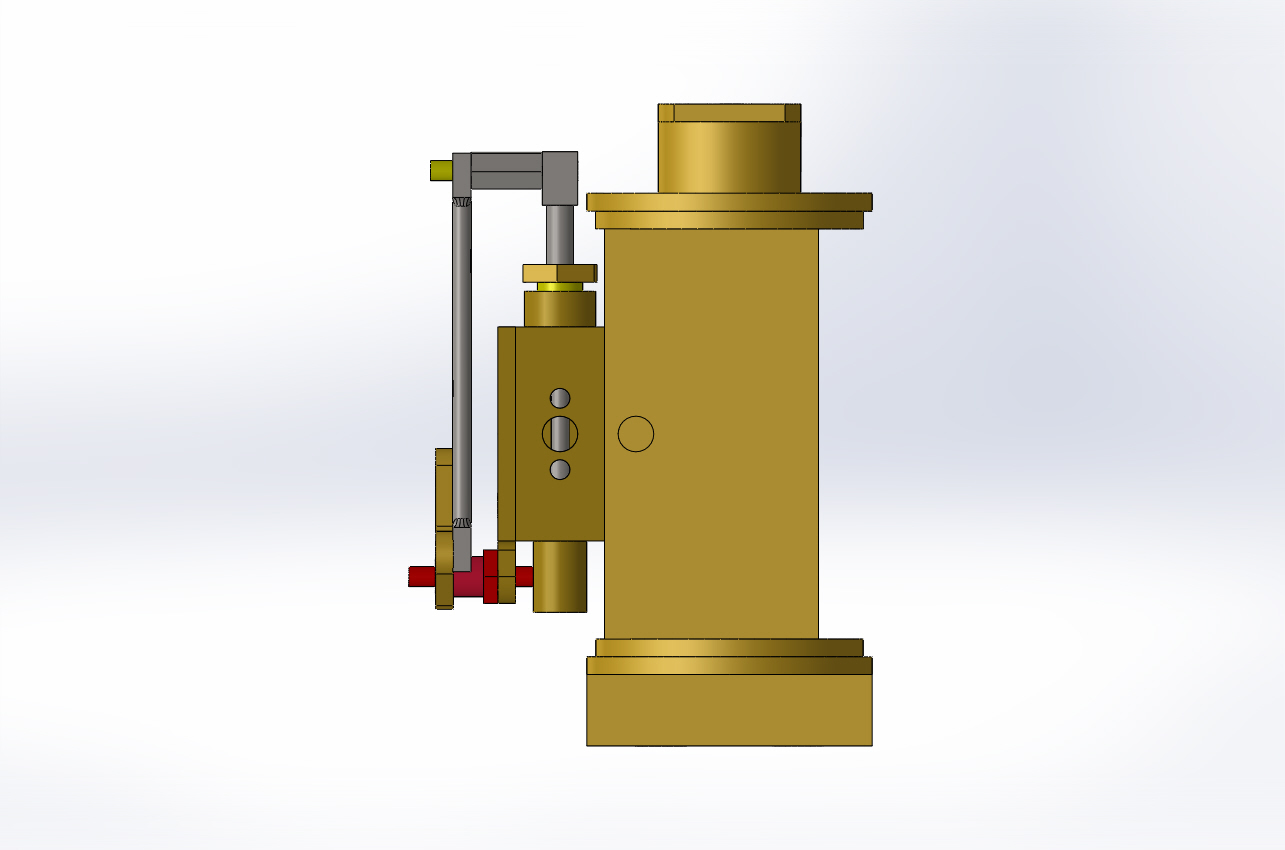
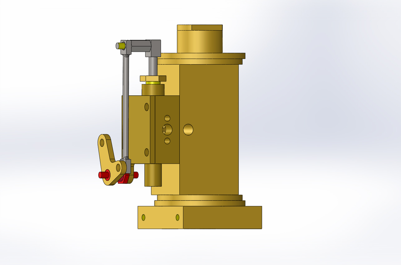
If I understand you correctly ... the drawing is correct. The Valve Link Bellcrank mounting hole (.125") is suppose to stop at the .141" diameter lip. That leaves a gap between the Bellcrank surface and the Hex portion of the Mounting Post. This gap is needed so the Valve Link Rod can fit between the two. Take a look at post #288. There is a SW rendering that shows the placement of the Valve Link Rod. Look at post 260 there is a short U tube that also may help.I received Chris' parts today and of course I'm trying to assemble them. I noticed what I think is a dimention problem, which brought up a couple more questions. Sheet 14, Valve Link Bellcrank and Bellcrank Mounting Post. The BellCrank mounts on the mounting post which mounts to the Steam Chest Cover, right? If so, the mounting hole in the Bellcrank is too small. The sholder on the mounting post is .141" and the hole in the belcrank is .125".
I was a pencil and paper or ink and velum draftsman for a while some 44 years ago, but I don't recall a drafting symbol that looked like an upside down pine tree! For example, on sheet 14, on the drawing of the valve link rod, there is a dimention at the right end, that is .087 preceded by a o with a slash which I construe to mean diameter, followed by the pine tree symbol and 0.125 The latter is what I don't understand. Is it something new in CAD? Does it mean depth?
If anyone has these parts assembled and can post a picture, I would appreciate it.
Chuck
Chuck
I could make another better view if needed.
The upside down tree is depth ... don't know it is used in this drawing since it is a thru hole.
Pat H.
chucketn
Senior Citizen
I must be thick, 'cause I don't see it! Can you do an exploded view or maybe an end view from the cylinder end?
I'm going out to the cooollldd workshop to see if I can come up with some 1/8" brass to make the piston rod hanger that's missing. Would aluminum do? I think I have some 1/8" aluminum rod.
Chuck
I'm going out to the cooollldd workshop to see if I can come up with some 1/8" brass to make the piston rod hanger that's missing. Would aluminum do? I think I have some 1/8" aluminum rod.
Chuck
chucketn
Senior Citizen
Pat,
I found some 1/8" brazing rod I think, and made the missing part. It's kinda red looking compared to brass.
I now have the piston rod hung from the beam!
Can't wait to get Mike and Mike's parts(where have I heard that before?).
Chuck
I found some 1/8" brazing rod I think, and made the missing part. It's kinda red looking compared to brass.
I now have the piston rod hung from the beam!
Can't wait to get Mike and Mike's parts(where have I heard that before?).
Chuck
chucketn
Senior Citizen
Take your time, Pat. No rush.
Chuck
Chuck
chucketn
Senior Citizen
Last edited:
chucketn
Senior Citizen
ninefinger, how you doing? Do you need help?
Chuck
Chuck
Try again. Dave was able to view the images. Also my link worked.
Pat H.
chucketn
Senior Citizen
Nope. Still can't connect to it. In fact, the links in your post have the dredded 'NO' symbol.
Chuck


Chuck


Similar threads
- Replies
- 6
- Views
- 856


![MeshMagic 3D Free 3D Modeling Software [Download]](https://m.media-amazon.com/images/I/B1U+p8ewjGS._SL500_.png)


