Team Build 8

Home Model Engine Machinist Forum

Help Support Home Model Engine Machinist Forum:

This site may earn a commission from merchant affiliate links, including eBay, Amazon, and others.
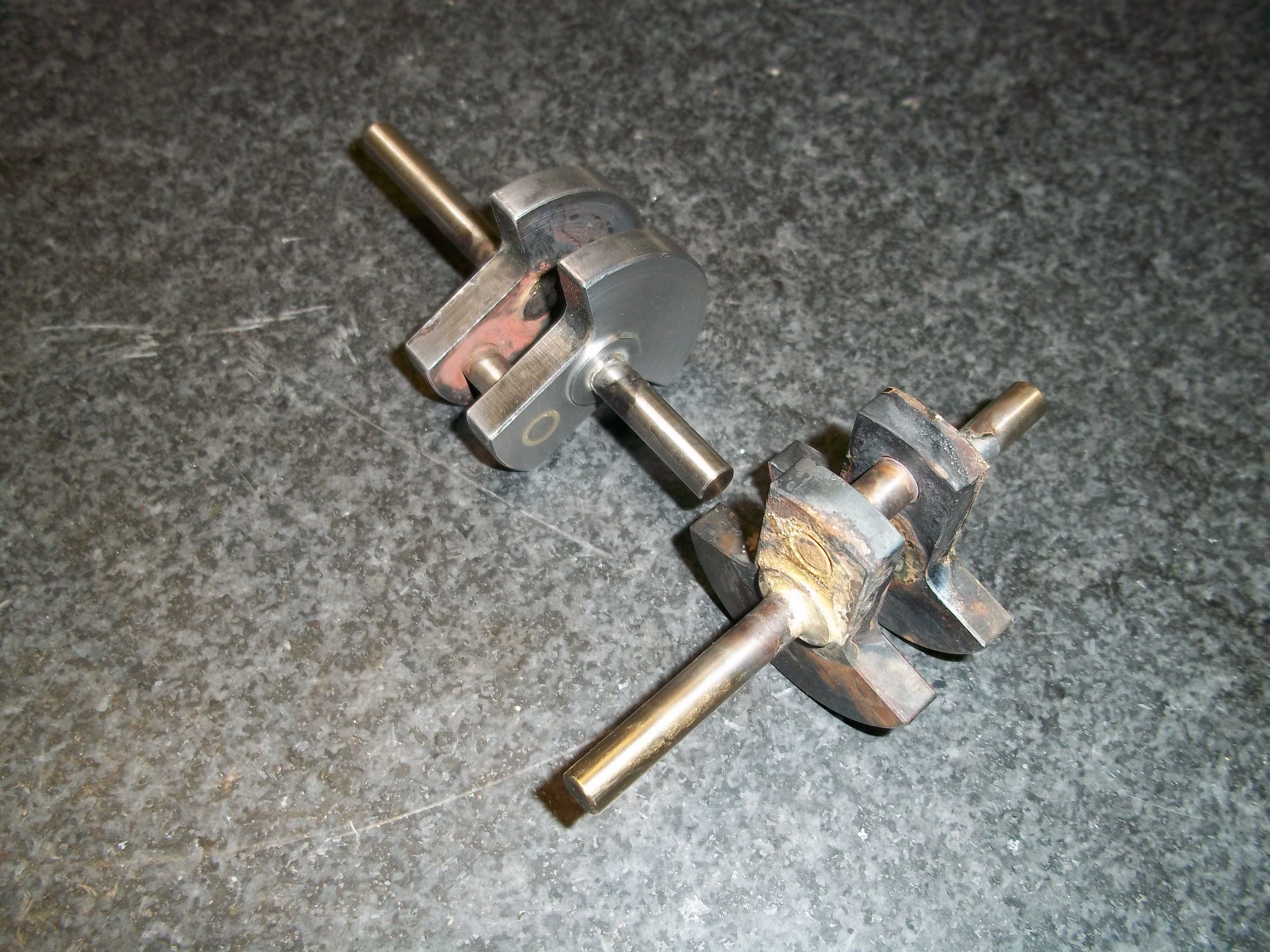
Good news and a bit of bad. I started to silver braze the crankshaft bits.
The first is a loss, the second is just a mess, the third might be passable
after some cleanup work. As the process is developed, the parts should come out quicker and nicer. I hope I made enough extras.

Regards to all;
Maverick
 
Just checking in with our missing parts. How are you doing? Not sure what parts are outstanding.

Dave
 
Guys,

I haven't given up - yet! I completed 1 of the eccentric straps after coming so close and then trashing the 1st one. I have a process now - I just need to eek out a couple of hours together so I can run a bunch without interruptions (which is part of the cause of the 1st ruined part.. )
I'll check back in next Monday - this week holds some promise of a bit of free time - my apologies for the extreme delay - life has gotten in the way of play (I haven't been cheating and making other projects either - just no shop time at all :(

Mike
 
Mike,

Great to hear that you are on your way to finishing your parts. Thanks for responding to my PM ... :)

Are the straps the only parts left?

Looking forward to next Monday. :cool:

Pat H.
 
Here is a peek at the crankshaft progress. The one in the foreground is
freshly silver brazed and the other has had a bit of cleanup.

crankshafts.jpg


My previous silver brazing experience was on carbide form tools and various industrial repairs where appearance was secondary. There is quite an art to keeping the silver confined to just the joint and not run all over the place. I was happy to find that runout was minimal after the main shaft was cut.

Regards,
Maverick
 
Maverick,

Looking good Thm:...
If you can ... it would be nice the see your brazing setup.

Thanks for the update and picture.

Pat H.
 
Sweet :)
There is a fair bit of work sitting there in that crank assembly :eek:
 
As Chuck said an Update would be great. I dont care how long it take but at least update us. Let us know if we can help.

Dave
 
I've started making the missing parts. I have completed the beam pivot bearings and started the crankshaft bearings.
I have found there is a problem with the linkages over the piston rod. Something is too long as the crosshead link mounting and the piston rod mounting foul each other. Anyone else find this?

Chuck
 
Chuck,

So far I have not been able to see the problem.
SolidWorks does not show any interference between any linkages.
Just to clarify .."crosshead link mounting" is on page 17, there it is called "crosshead link mounting block" also known as item 35. Is that the correct part?

Also I'm not sure what the "piston rod mounting" is ... can you verify for me?
Maybe a photo would help.

Another question ... is it the fasteners that are touching?

Thanks,

Pat H
 
Last edited:
I'll take a picture in a bit.Got to have my coffee first.
The piston rod mounting is the clevis on the end of the piston rod. The interference is greater than the heads of the fasteners.

Chuck
 
I think I've figured it out. Remember the discussion on the missing drawing? I made the pin/spacer that connects the piston rod to the drop llnks too long. I'll trim it and check the fit.

Chuck
 
I shortened the part mentioned to minimum length, but that was not enough. The interference remained. I then added a #2 brass washer to each end of the brass frame support in front of the drop link support. The washers would need to be trimmed in diameter, but they are a temporary fix.
I have attached pictures of the interference points and the washer locations.
Let me know if anyone else runs into this problem.
Chuck

interference1.jpg


interference2.jpg


washer1.jpg


washer2.jpg
 
Chuck,

Great pictures ... helps a lot. :)

See page 17, the Cylinder Rod End Bushing Bolt needs a head thickness of .030". Yours looks a lot thicker.
This will leave about .063" for the Ground Link Bushing Bolt head. That bolt may also need trimming a little. Other parts may also thinning a tad as well. It just depends on the thickness stack up. Also consider the Grounding Link Spacer Bushing (page 15) maybe instead of .093" trim it down to say .090". This gives a little more room. Whatever adjustment needed ... do both sides.

Thanks for the update... looks like your coming along nicely,

Pat H
 
Chuck,

That's looking pretty good. I know its not finished but I'd like to see more!

Also, what part of E TN are you in? I'm in N AL.
 
JW,
I'm near Jonesborough, just off I81. I used to have inlaws in Huntsville many years ago.
As you know, this is a team build. This(see pic below) is where we're at so far. If you go back to the first couple pages of this thread, you'll find the plans we're working from.

Chuck

DSCF1405.jpg
 
Chuck,

Nice to see some one close. I work in Huntsville and live a short piece from I65 (I'm sure you know I65).

I didn't download the plans for this build but I've followed all the way as I'm very interested in doing a team build but have to finish the 4 I'm working on now (and upload some pics so people can "trust" me).

Do you know of any clubs or groups for model engineering down here in the SE?

I'd love to not be the only person I know who is into model engines.
 
JW,
I'm in the same boat here. Not many into this hobby here either. Yhat's why I'm a member on so many hobby machinist forums.

Chuck
 
Back
Top