You are using an out of date browser. It may not display this or other websites correctly.
You should upgrade or use an alternative browser.
You should upgrade or use an alternative browser.
Stuart No. 4 build
- Thread starter smfr
- Start date

Help Support Home Model Engine Machinist Forum:
This site may earn a commission from merchant affiliate
links, including eBay, Amazon, and others.
vcutajar
Well-Known Member
- Joined
- Nov 6, 2011
- Messages
- 862
- Reaction score
- 168
Hi Simon
Glad you are back. There is always one part in any project which I always have to redo. I have already done the shaft of the cam twice in the Kiwi and I have a suspicion that I have to redo it a third time. Only consolation is that the more you redo the same part, the quicker its finished.
Vince
Glad you are back. There is always one part in any project which I always have to redo. I have already done the shaft of the cam twice in the Kiwi and I have a suspicion that I have to redo it a third time. Only consolation is that the more you redo the same part, the quicker its finished.
Vince
- Joined
- Mar 13, 2012
- Messages
- 583
- Reaction score
- 62
It's good to see you at it again. That is an interesting way to build up the split bearing. I never would have thought of it that way.
Is there enough clearance in the engine design to run it with a con-rod that has a reverse taper? I think I'd use it as it is as long as there is room to clear the small end. It is a great looking part, and if it functions to boot, then there is nothing to worry about
Is there enough clearance in the engine design to run it with a con-rod that has a reverse taper? I think I'd use it as it is as long as there is room to clear the small end. It is a great looking part, and if it functions to boot, then there is nothing to worry about
- Joined
- Oct 29, 2011
- Messages
- 284
- Reaction score
- 2
rhitee93 said:It's good to see you at it again. That is an interesting way to build up the split bearing. I never would have thought of it that way.
Yeah, I wondered whether it was a sensible way. It's very wasteful of material, but it does ensure that it's easy to drill the holes aligned. I'm sure I could have got away with two rectangular hunks of bronze. If I had steel bar of the right size, I would have used that too.
I'm sure there's room in the engine, but it would bug me every time I look at it!rhitee93 said:Is there enough clearance in the engine design to run it with a con-rod that has a reverse taper? I think I'd use it as it is as long as there is room to clear the small end. It is a great looking part, and if it functions to boot, then there is nothing to worry about
Don1966
Senior Member
- Joined
- Jan 19, 2012
- Messages
- 487
- Reaction score
- 24
Hi Simon glad to see you back and mishaps do happen just regroup and pull yourself up and hit it again. If you look under my post you will see my saying " how many times I did that!"
The engine I am working on now has plenty of redo's and broken taps. It all comes with learning. Sometimes I will ask why me? But I find myself starting to think things through a lot more now because of the mishaps. The learning process is starting to kick in and hopefully less redo's.
Don
The engine I am working on now has plenty of redo's and broken taps. It all comes with learning. Sometimes I will ask why me? But I find myself starting to think things through a lot more now because of the mishaps. The learning process is starting to kick in and hopefully less redo's.
Don

$99.99
AHS Outdoor Wood Boiler Yearly Maintenance Kit with Water Treatment - ProTech 300 & Test Kit
Alternative Heating & Supplies

$89.99
Outdoor Wood Boiler Water Treatment Rust Inhibitor- AmTech 300 & Test Kit
Alternative Heating & Supplies

$519.19
$699.00
FoxAlien Masuter Pro CNC Router Machine, Upgraded 3-Axis Engraving All-Metal Milling Machine for Wood Acrylic MDF Nylon Carving Cutting
FoxAlien Official

$29.95
Competition Engine Building: Advanced Engine Design and Assembly Techniques (Pro Series)
Amazon.com Services LLC
![DreamPlan Home Design and Landscaping Software Free for Windows [PC Download]](https://m.media-amazon.com/images/I/51kvZH2dVLL._SL500_.jpg)
$0.00
DreamPlan Home Design and Landscaping Software Free for Windows [PC Download]
Amazon.com Services LLC

$94.99
$109.99
AHS Woodmaster 4400 Maintenance Kit for Outdoor Wood Boiler Treatment
Alternative Heating & Supplies

$39.58
$49.99
Becker CAD 12 3D - professional CAD software for 2D + 3D design and modelling - for 3 PCs - 100% compatible with AutoCAD
momox Shop

$25.34
$34.99
Bowl Sander Tool Kit w/Dual Bearing Head & Hardwood Handle | 42PC Wood Sander Set | 2" Hook & Loop Sanding Disc Sandpaper Assortment | 1/4" Mandrel Bowl Sander for Woodturning | Wood Lathe Tools
Peachtree Woodworking Supply Inc

$45.99
Sunnytech Mini Hot Air Stirling Engine Motor Model Educational Toy Kits Electricity HA001
stirlingtechonline

$39.99
$49.99
Sunnytech Low Temperature Stirling Engine Motor Steam Heat Education Model Toy Kit For mechanical skills (LT001)
stirlingtechonline
- Joined
- Oct 29, 2011
- Messages
- 284
- Reaction score
- 2
I wasn't looking forward to hogging another hunk of steel, so I picked up what was left of the gunmetal casting, and decided to make a franken-rod of the old and new parts! I'd use the gunmetal casting, but re-use the split bronze bearing from previous mistake.
One of the tricky things with castings is that they don't have any flat surfaces, so setting up a datum, especially on something this shape, is a PITA. I had previously marked some centers on the ends. Does anyone have a good tip for picking up a punch mark on the side of something? I feel like some combination of bench centers and a dividing head would be good for marking out rough parts with rotational symmetry.
Anyway, I managed to square up the little end of the casting as best I could, as well as sawing down the remains of the big end, then set up in the vise:
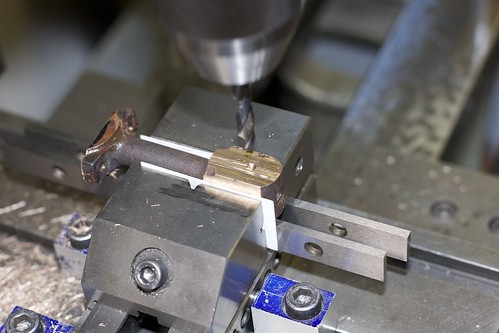
I trimmed down the big end with an end mill, then laid out the little end hole accurately from that, taking the thickness of the split bearing into account, and drilled and reamed for the crosshead pin.
This makes it clearer which parts I'm reusing:
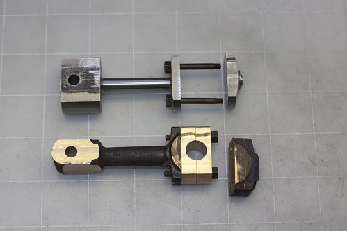
The end cap needs milling down, which was a bit tricky since there's so little to grab onto. Paper shims in the vise helped to avoid slipping, and it was OK. Since there's a bit of play in the bolt holes, I use some drill rod bits to align the two holes before tightening up the bolts:
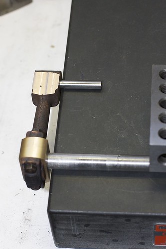
Here I'm checking that the punch holes on the two ends are reasonably aligned by shimming up one end with shims that correspond to the difference in radius of the two rods:
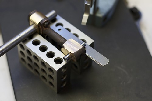
And here we are, reading for some turning (again!)
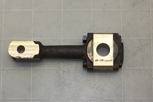
First I turned the shaft down to a constant thickness. Just as before, the bolts get in the way of finishing the top surface of the big end:
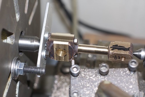
but I can unbolt it, and that cylindrical shaft allows me to mark out a center point on the upper portion of the casting:
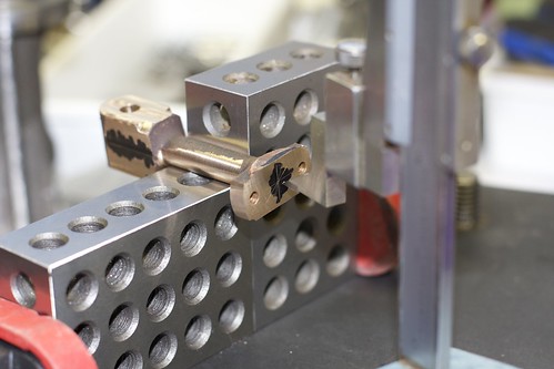
which is lightly center-drilled. This will be hidden by the bearings after assembly.
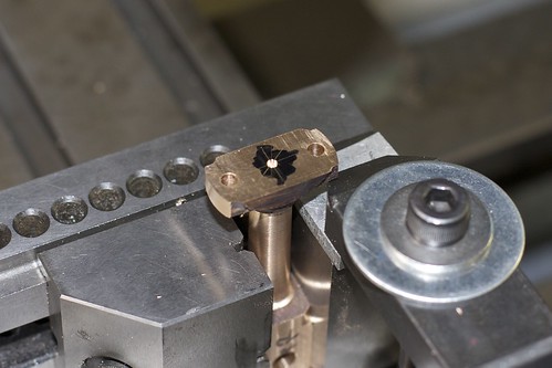
Now this part of the casting can go onto the lathe for turing between centers. Here I'm setting the angle of the top slide; I have an indicator clamped onto the top slide, I zero it at one end, then crank away with the little handle ;D, looking at the delta between the two ends. When this is roughly equivalent to the difference in radius between the two ends of the taper (1/64" in this case), I know that the angle is close.
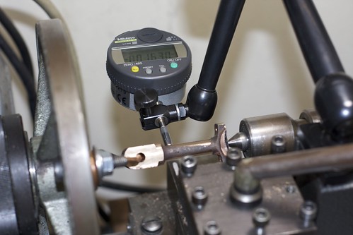
Of course, before cutting I double-check that the taper is going the right way
Success!
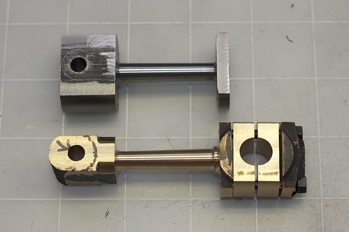
I left a little shoulder on the right-hand side for decoration (though I wish I'd considered the final thickness of the part, since I ended off skimming parts off this).
More to come...
One of the tricky things with castings is that they don't have any flat surfaces, so setting up a datum, especially on something this shape, is a PITA. I had previously marked some centers on the ends. Does anyone have a good tip for picking up a punch mark on the side of something? I feel like some combination of bench centers and a dividing head would be good for marking out rough parts with rotational symmetry.
Anyway, I managed to square up the little end of the casting as best I could, as well as sawing down the remains of the big end, then set up in the vise:

I trimmed down the big end with an end mill, then laid out the little end hole accurately from that, taking the thickness of the split bearing into account, and drilled and reamed for the crosshead pin.
This makes it clearer which parts I'm reusing:

The end cap needs milling down, which was a bit tricky since there's so little to grab onto. Paper shims in the vise helped to avoid slipping, and it was OK. Since there's a bit of play in the bolt holes, I use some drill rod bits to align the two holes before tightening up the bolts:

Here I'm checking that the punch holes on the two ends are reasonably aligned by shimming up one end with shims that correspond to the difference in radius of the two rods:

And here we are, reading for some turning (again!)

First I turned the shaft down to a constant thickness. Just as before, the bolts get in the way of finishing the top surface of the big end:

but I can unbolt it, and that cylindrical shaft allows me to mark out a center point on the upper portion of the casting:

which is lightly center-drilled. This will be hidden by the bearings after assembly.

Now this part of the casting can go onto the lathe for turing between centers. Here I'm setting the angle of the top slide; I have an indicator clamped onto the top slide, I zero it at one end, then crank away with the little handle ;D, looking at the delta between the two ends. When this is roughly equivalent to the difference in radius between the two ends of the taper (1/64" in this case), I know that the angle is close.

Of course, before cutting I double-check that the taper is going the right way
Success!

I left a little shoulder on the right-hand side for decoration (though I wish I'd considered the final thickness of the part, since I ended off skimming parts off this).
More to come...
- Joined
- Oct 29, 2011
- Messages
- 284
- Reaction score
- 2
Now to clean up the big end with the split bearing. This is where it starts looking more like a connecting rod.
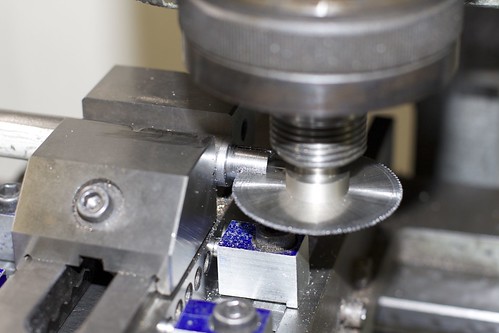
First I made an expanding arbor; chucked up some 1/2" cold-rolled rod, and turned down 1/2" at the end to 7/16", which is the bore diameter of the bearing. Then I drilled and tapped for M6, and countersunk. I'm going to use a countersunk screw to make it expand. I sawed cuts at 90° to allow for expansion (another successful slitting saw operation!).
Now the conrod is attached to the arbor and can be turned. Here I've started to clean up one side.
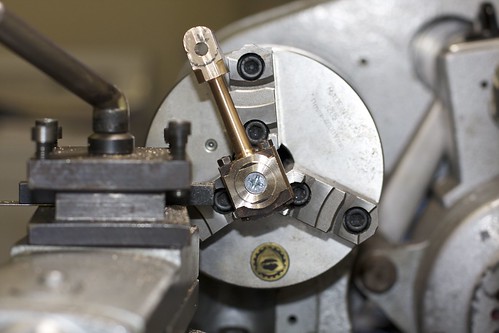
It's so satisfying seeing the casting and the split bearing merge into one as they get turned down together!
I have to be careful to take the right amount of each side; here again I wish I had some better setup for measuring.
After turning both sides, here's where I'm at:
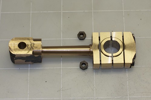
Sadly I can't test the fit on the crankshaft yet, because the crankshaft journal has a pretty significant radius that I need to replicate on this bearing. I need to think about whether to grind a tool to cut the radius, or do it some other way.
First I made an expanding arbor; chucked up some 1/2" cold-rolled rod, and turned down 1/2" at the end to 7/16", which is the bore diameter of the bearing. Then I drilled and tapped for M6, and countersunk. I'm going to use a countersunk screw to make it expand. I sawed cuts at 90° to allow for expansion (another successful slitting saw operation!).

Now the conrod is attached to the arbor and can be turned. Here I've started to clean up one side.

It's so satisfying seeing the casting and the split bearing merge into one as they get turned down together!
I have to be careful to take the right amount of each side; here again I wish I had some better setup for measuring.
After turning both sides, here's where I'm at:

Sadly I can't test the fit on the crankshaft yet, because the crankshaft journal has a pretty significant radius that I need to replicate on this bearing. I need to think about whether to grind a tool to cut the radius, or do it some other way.
Very nice rescue Simon, you've done a great job on it.
You will find that you will always have problems marking out castings, purely because they are all sorts of shapes and angles.
Having investment castings (lost wax process) helps a lot, and on those, because of the way they are made, they don't need release angles etc, so come out almost perfect size and shape, but they are usually very expensive.
I get around the marking out problem by machining a datum to work from, then at the very end, rough up the machined area to make it look like it was original.
But of course, everyone has their own way of doing things.
Nice one :bow:
John
- Joined
- Oct 29, 2011
- Messages
- 284
- Reaction score
- 2
This is almost where I left off last time:
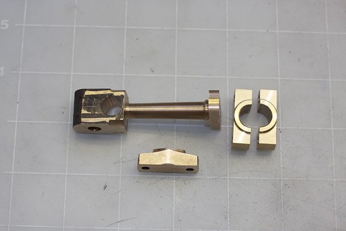
but I've done some hand filing on the end cap, and drilled and reamed what will become the bottom of the yoke. I regret not leaving a bit more material at the small end of the taper, but I think it will be OK. I decided to form the bottom of the yoke because I wanted to shape the shoulders, and to know what the profile will end up like.
I broke out the ball-turner to form the shoulders, turning between centers of course:
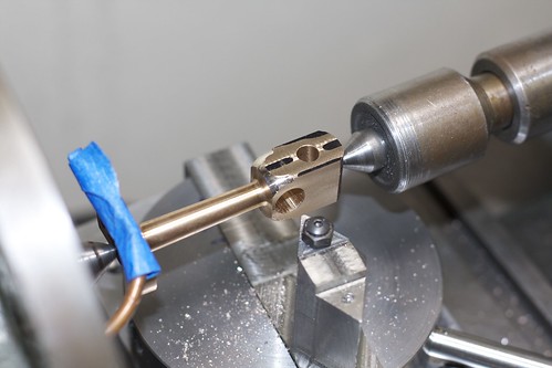
It's always a bit of a puzzler to work out the combination of placement and rotation with this thing, and I usually end up doing it by eye.
Next up was cut out the center of the yoke. For most of the material removal, I had the part clamped in a screwless vise. However, as soon as I broke through the bottom, the part loosened and moved slightly; not a big deal but stupid here then decided to just tighten the vise, which squished the Y, pushing the sides of of alignment ;D. Some judicious hand-bending with some 1/4" drill rod through the crosshead pin holes got it back into shape!
So to finish off the Y, I clamped it down securely:
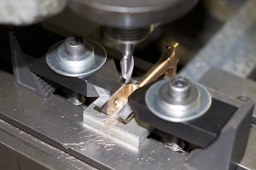
Then it was onto the rounding table to finish off the radius on the end:
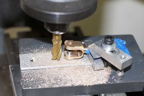
The top arm is flapping in the breeze a bit with this setup, and had enough flex that I think it was getting pulled up by the end mill, resulting in a non-square profile. I was able to flip the part over and tidy that up, however.
A bit of draw filing, and the part is almost done:
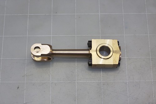
What remains is still to put a radius on the journal bore to fit the crankshaft.

but I've done some hand filing on the end cap, and drilled and reamed what will become the bottom of the yoke. I regret not leaving a bit more material at the small end of the taper, but I think it will be OK. I decided to form the bottom of the yoke because I wanted to shape the shoulders, and to know what the profile will end up like.
I broke out the ball-turner to form the shoulders, turning between centers of course:

It's always a bit of a puzzler to work out the combination of placement and rotation with this thing, and I usually end up doing it by eye.
Next up was cut out the center of the yoke. For most of the material removal, I had the part clamped in a screwless vise. However, as soon as I broke through the bottom, the part loosened and moved slightly; not a big deal but stupid here then decided to just tighten the vise, which squished the Y, pushing the sides of of alignment ;D. Some judicious hand-bending with some 1/4" drill rod through the crosshead pin holes got it back into shape!
So to finish off the Y, I clamped it down securely:

Then it was onto the rounding table to finish off the radius on the end:

The top arm is flapping in the breeze a bit with this setup, and had enough flex that I think it was getting pulled up by the end mill, resulting in a non-square profile. I was able to flip the part over and tidy that up, however.
A bit of draw filing, and the part is almost done:

What remains is still to put a radius on the journal bore to fit the crankshaft.
- Joined
- Oct 29, 2011
- Messages
- 284
- Reaction score
- 2
It's been a few weeks since I've managed to get time in the shop (garage!), but I got a few things done today.
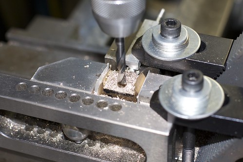
Here's my setup for the crosshead milling:
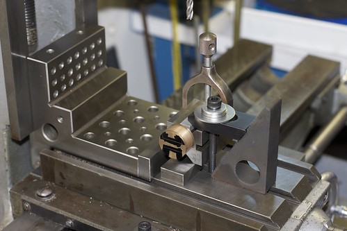
I have the crosshead on the piston rod in a V-block, because I want the milled parts to be parallel with the piston rod. The angle plate etc. is just there to line things up. I clamped my screwless vise on its side around the crosshead for milling, which made things a little cramped:
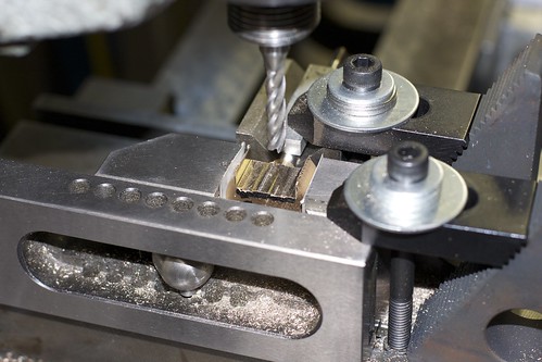
After doing one side, I had to tear down the setup, turn the part around (making sure that the side to be cut is parallel with the part I just milled out, using the height gauge). Had I been thinking more clearly, I would have had the V-block on its side for the first part, then I could have just flipped it over.
Once both sides were milled, the crosshead pin hole was drilled and reamed in the same setup:
Here's the result, with its companion connecting rod:
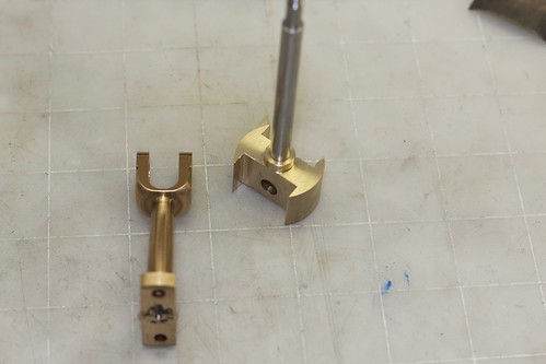
Before milling, the crosshead was a nice sliding fit in the standard, but the milling pushed those skinny flaps out (this being bronze), and tightened everything up. A bit of fussing around was required to get it sliding in the standard again.
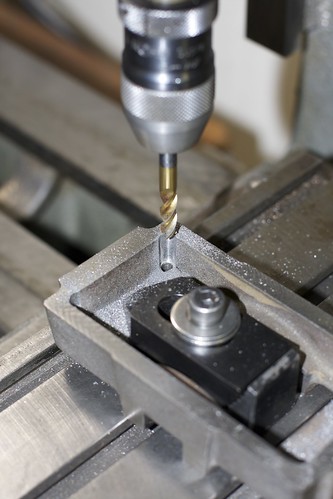
After that I drilled and tapped the boxbed for the studs that hold down the soleplate. The alignment of the soleplate on the boxbed was mostly by eye/feel. I transferred the holes by positioning the two parts under the mill, with the clearance drill bit just dropping into the existing hole in the soleplate. I then switched to the smaller tapping drill size, and drilled down into the boxbed. The 4 holes were then tapped 2BA.
One annoyance here is that the stud holes in the soleplate go down the inside corners of the casting, which ends up pushing the drill out of line, and causing the studs to catch. To fix that I milled out some room on each corner, centered on the holes:
I'm close to being able to have this thing crank the crosshead up and down! I spent some time fitting the split bearing on the connecting rod to the crankshaft journal, but it still needs some wearing in.
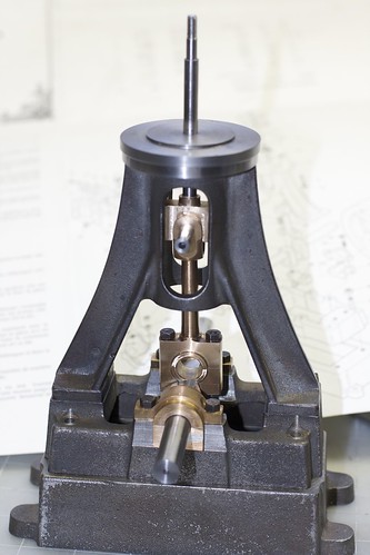
I just need to drill and tap the studs for the standard, and make the crosshead pin, and then I can have it turn over.
Here's my setup for the crosshead milling:

I have the crosshead on the piston rod in a V-block, because I want the milled parts to be parallel with the piston rod. The angle plate etc. is just there to line things up. I clamped my screwless vise on its side around the crosshead for milling, which made things a little cramped:

After doing one side, I had to tear down the setup, turn the part around (making sure that the side to be cut is parallel with the part I just milled out, using the height gauge). Had I been thinking more clearly, I would have had the V-block on its side for the first part, then I could have just flipped it over.
Once both sides were milled, the crosshead pin hole was drilled and reamed in the same setup:

Here's the result, with its companion connecting rod:

Before milling, the crosshead was a nice sliding fit in the standard, but the milling pushed those skinny flaps out (this being bronze), and tightened everything up. A bit of fussing around was required to get it sliding in the standard again.
After that I drilled and tapped the boxbed for the studs that hold down the soleplate. The alignment of the soleplate on the boxbed was mostly by eye/feel. I transferred the holes by positioning the two parts under the mill, with the clearance drill bit just dropping into the existing hole in the soleplate. I then switched to the smaller tapping drill size, and drilled down into the boxbed. The 4 holes were then tapped 2BA.
One annoyance here is that the stud holes in the soleplate go down the inside corners of the casting, which ends up pushing the drill out of line, and causing the studs to catch. To fix that I milled out some room on each corner, centered on the holes:

I'm close to being able to have this thing crank the crosshead up and down! I spent some time fitting the split bearing on the connecting rod to the crankshaft journal, but it still needs some wearing in.

I just need to drill and tap the studs for the standard, and make the crosshead pin, and then I can have it turn over.


