You are using an out of date browser. It may not display this or other websites correctly.
You should upgrade or use an alternative browser.
You should upgrade or use an alternative browser.
Stuart No. 4 build
- Thread starter smfr
- Start date

Help Support Home Model Engine Machinist Forum:
This site may earn a commission from merchant affiliate
links, including eBay, Amazon, and others.
zeeprogrammer
Well-Known Member
- Joined
- Mar 14, 2009
- Messages
- 3,362
- Reaction score
- 13
I haven't been on the forum much lately...
But tonight right away I ran into this thread (again) and read through it.
Excellent stuff. Great pictures too.
I really appreciate the detail and approaches taken. Gives a newbie a feeling of optimism.
Most of us know the extra work it takes just to take pictures and record one's progress. Very much appreciated.
As I'd said in a (much) earlier post...Stuart models was one of the first things that got me interested in this hobby as a kid. Your work is quality.
rklopp
Well-Known Member
- Joined
- Oct 6, 2008
- Messages
- 399
- Reaction score
- 112
Simon
Good move on the drill guide inside the steam chest. When I built mine, I was naive and did not think to use a guide. The drill walked. I ended up making the end of the valve rod eccentric, which makes for interesting times putting the engine together. If I'd only known then what I know now, 40 years hence.
Best,
RKlopp
- Joined
- Oct 29, 2011
- Messages
- 284
- Reaction score
- 2
Another Sunday, another day in the shop 
I got the other side of the valve chest gland profile rounded off, but here's what happens when you go a bit too far on the rounding table:
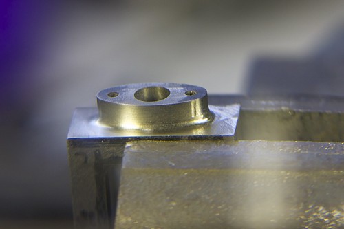
I should be able to take it out by filing.
I milled the valve chest down to about the right thickness; the outer side is non-critical, and I left is slightly thick because otherwise I start running into the radii for the valve guide and the gland thingy.
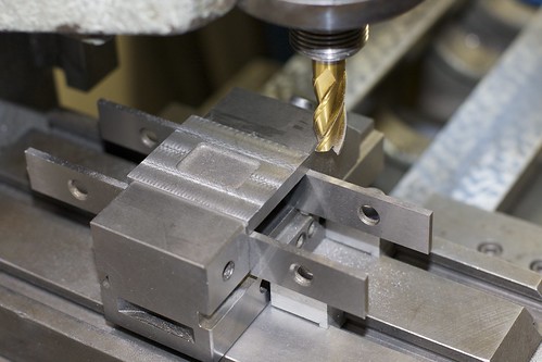
Now the valve cover gets a cleanup, first with an old end mill of unknown sharpness, to get through the crust, and then with a nice sharp one on a finish pass:
Then I did something that I might regret, which is to clean up the center indentation. Not having any ball-end mills, I used a little carbide burr that came with the Dremel:
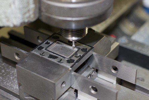
It did the job OK, but I'll have to file away some of the machining marks. I'll need some riffler files to get into the concavity. I say I might regret it because it might make the cover look too too machined, and not like a casting. I guess it depends on how I paint it.
While marking out the valve cover for final size, I also marked out the stud holes:
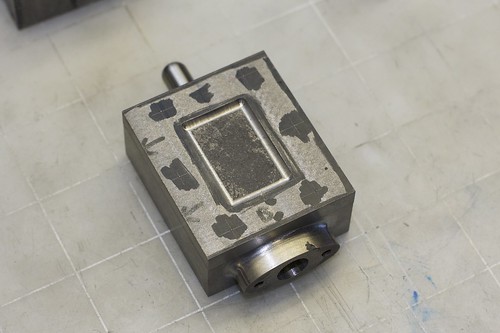
It's another crazy setup! I wanted to drill the cover, valve chest and piston all at the same time to ensure that all the stud holes lined up. So I came up with a setup, using the angle plate as a backing, a 1-2-3 block on each side between which the parts could be clamped, and some spacers at the back to align the top edges of the parts:
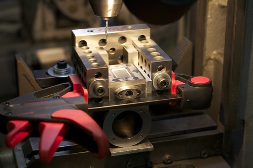
Some cardboard takes up the slight differences in thickness between the parts. I set this up so that, if need be, I could repeatably remove and replace the valve chest and cover to drill the piston itself. It turns out I didn't need to do that. One problem with this setup was that the holes are pretty deep, so the drill chuck could hit the 1-2-3 blocks. I had to use a full length drill bit (slightly undersize for the tapping size) to go all the way down into the piston. This worked fine, but I did manage to drill through into the exhaust hole. :-\ Oh well, that's not under pressure so it shouldn't be a problem.
The holes in the chest and cover were then opened up to clearance size (#27) with the part held in a screwless vise, held by hand. Then the holes in the piston were drilled to tapping size (#33), the 4BA taper tap started in the mill by hand, then tapping completed using a tap wrench.
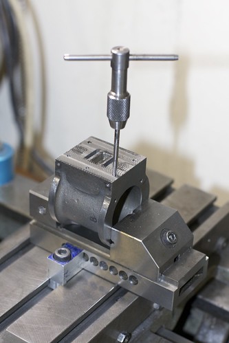
Always a bit nerve-wracking on a part into which many hours have gone, but it went fine.
Now for a test fit:
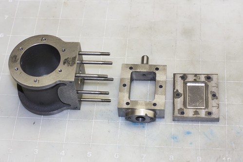
All the studs look straight, which is a good sign. And the valve chest and cover fit nicely over the studs, so my drilling in-place seems to have paid off.
To end the day, some mock assembly pictures to see how everything fits together:
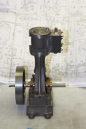
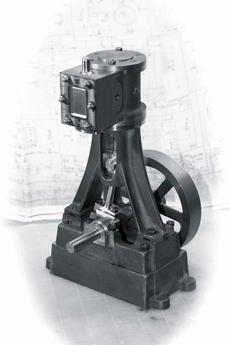
I have yet to drill the steam hole in the valve chest. I see some engines with steam and exhaust on one side (keep all the pipes together?), and some with steam in one side, exhaust the other. I'm not sure which I want yet.
Simon
I got the other side of the valve chest gland profile rounded off, but here's what happens when you go a bit too far on the rounding table:

I should be able to take it out by filing.
I milled the valve chest down to about the right thickness; the outer side is non-critical, and I left is slightly thick because otherwise I start running into the radii for the valve guide and the gland thingy.
Now the valve cover gets a cleanup, first with an old end mill of unknown sharpness, to get through the crust, and then with a nice sharp one on a finish pass:

Then I did something that I might regret, which is to clean up the center indentation. Not having any ball-end mills, I used a little carbide burr that came with the Dremel:

It did the job OK, but I'll have to file away some of the machining marks. I'll need some riffler files to get into the concavity. I say I might regret it because it might make the cover look too too machined, and not like a casting. I guess it depends on how I paint it.
While marking out the valve cover for final size, I also marked out the stud holes:

It's another crazy setup!

Some cardboard takes up the slight differences in thickness between the parts. I set this up so that, if need be, I could repeatably remove and replace the valve chest and cover to drill the piston itself. It turns out I didn't need to do that. One problem with this setup was that the holes are pretty deep, so the drill chuck could hit the 1-2-3 blocks. I had to use a full length drill bit (slightly undersize for the tapping size) to go all the way down into the piston. This worked fine, but I did manage to drill through into the exhaust hole. :-\ Oh well, that's not under pressure so it shouldn't be a problem.
The holes in the chest and cover were then opened up to clearance size (#27) with the part held in a screwless vise, held by hand. Then the holes in the piston were drilled to tapping size (#33), the 4BA taper tap started in the mill by hand, then tapping completed using a tap wrench.

Always a bit nerve-wracking on a part into which many hours have gone, but it went fine.
Now for a test fit:

All the studs look straight, which is a good sign. And the valve chest and cover fit nicely over the studs, so my drilling in-place seems to have paid off.
To end the day, some mock assembly pictures to see how everything fits together:


I have yet to drill the steam hole in the valve chest. I see some engines with steam and exhaust on one side (keep all the pipes together?), and some with steam in one side, exhaust the other. I'm not sure which I want yet.
Simon

$29.95
Competition Engine Building: Advanced Engine Design and Assembly Techniques (Pro Series)
Amazon.com Services LLC
![DreamPlan Home Design and Landscaping Software Free for Windows [PC Download]](https://m.media-amazon.com/images/I/51kvZH2dVLL._SL500_.jpg)
$0.00
DreamPlan Home Design and Landscaping Software Free for Windows [PC Download]
Amazon.com Services LLC

$94.99
$109.99
AHS Woodmaster 4400 Maintenance Kit for Outdoor Wood Boiler Treatment
Alternative Heating & Supplies

$39.58
$49.99
Becker CAD 12 3D - professional CAD software for 2D + 3D design and modelling - for 3 PCs - 100% compatible with AutoCAD
momox Shop

$89.99
Outdoor Wood Boiler Water Treatment Rust Inhibitor- AmTech 300 & Test Kit
Alternative Heating & Supplies

$99.99
AHS Outdoor Wood Boiler Yearly Maintenance Kit with Water Treatment - ProTech 300 & Test Kit
Alternative Heating & Supplies

$519.19
$699.00
FoxAlien Masuter Pro CNC Router Machine, Upgraded 3-Axis Engraving All-Metal Milling Machine for Wood Acrylic MDF Nylon Carving Cutting
FoxAlien Official

$39.99
$49.99
Sunnytech Low Temperature Stirling Engine Motor Steam Heat Education Model Toy Kit For mechanical skills (LT001)
stirlingtechonline

$45.99
Sunnytech Mini Hot Air Stirling Engine Motor Model Educational Toy Kits Electricity HA001
stirlingtechonline

$25.34
$34.99
Bowl Sander Tool Kit w/Dual Bearing Head & Hardwood Handle | 42PC Wood Sander Set | 2" Hook & Loop Sanding Disc Sandpaper Assortment | 1/4" Mandrel Bowl Sander for Woodturning | Wood Lathe Tools
Peachtree Woodworking Supply Inc
I'm not criticising your work Simon, far from it, just bringing up a failure point of most Stuart engine designs.
The left hand picture above shows what I mean perfectly. The flywheel hanging in mid air.
That will ensure the all crank related bearings will get unnecessary wear on them. From the very front one (nearest the flywheel) to the back one AND the big end in between.
Just as a suggestion, I would machine up a small support, so that the weight of the flywheel is taken to task with a bearing either side of it.
Lovely work BTW.
John
John,
that same problem I will have the day I will bring the Bernay(s) to completion. Not yet decided whether I should fit a supplementar bearing to the wood base or make a metal plate to put both the engine and bearing on.
If I took the additional trouble of making a split bearing, eventual adjustments would be easier.
Marcello
- Joined
- Aug 8, 2009
- Messages
- 929
- Reaction score
- 12
gbritnell said:Excellent work Simon. Your documentation is first rate.
gbritnell
Ditto.
- Joined
- Oct 29, 2011
- Messages
- 284
- Reaction score
- 2
I'm going to continue documentation of this build at madmodder: http://madmodder.net/index.php?topic=7362.0
- Joined
- Oct 29, 2011
- Messages
- 284
- Reaction score
- 2
What's happened here? Loads of posts missing etc?
NickG: see the "HMEM sold" thread, and other threads. Content posted here is now automatically copyrighted by Group Builder, not by the poster.
Simon


