
You are using an out of date browser. It may not display this or other websites correctly.
You should upgrade or use an alternative browser.
You should upgrade or use an alternative browser.
Philp Duclos "Victorian" IC engine Project
- Thread starter Cedge
- Start date


Help Support Home Model Engine Machinist Forum:
This site may earn a commission from merchant affiliate
links, including eBay, Amazon, and others.
Cedge
Well-Known Member
- Joined
- Jul 12, 2007
- Messages
- 1,727
- Reaction score
- 28
Thanks for the encouraging words, guys. They'll be needed as this one progresses....(grin)
So far no major road blocks beyond a couple of misprinted dimensions, but I've spotted all but one in time to move the location. Luckily, it looks like it won't hinder anything and there is already a plan B if it does.
Still lots of parts and pieces to make, but I've got the general idea of how things are supposed to work together, so maybe it will all go well. No one part is all that difficult, but, dear god, the thing sure has a bunch of them. It looks like the crank and con rod will be the next pieces to get made....a rather long single piece crank instead of the multi piece versions I'm used to.
Steamer
I'd be lost without my handy little table. It sprang to life last year after Marv Klotz shared a similar tool, he'd made, with the board. I took that basic idea and ran with it to make the one you see in the photo. It's quick to set up, lets me do many of the things a standard worm driven rotary table would, including indexed hole patterns on the mill. Not quite as critical as it once was since the new DRO has the bolt hole pattern function built in.
BC1...
Thanks for the feedback. You voiced exactly what I hoped I was achieving. You assured me it was happening.
Steve
Very nice work there Steve, as always, I have one question (may sound stupid!) but with the wiggler point, do you have it spinning and then pull down on it to mark the points, or is it stationary?, I have one and I've never thought of using it like that!
Giles
Giles
georgeseal
Well-Known Member
- Joined
- Jul 28, 2007
- Messages
- 105
- Reaction score
- 2
Giles,
You can use it either way with everything stationary it will just point to where you want.
If you have a center punch mark and bring the centered, spinning point into the hole then with draw it should be still concentric.
If it is spinning in a small arch then you are not centred on the hole
Hope this helps
Cedge
Well-Known Member
- Joined
- Jul 12, 2007
- Messages
- 1,727
- Reaction score
- 28
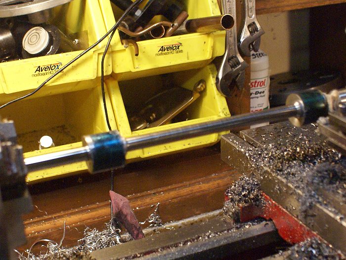
George's technique is an expansion on what I did in the photos. I used the needle with the mill turning about 500 rpm to pin point the critical locations and then I dropped the quill down so the needle "drilled" a mark. I then used a standard compass to scribe the circles.
The reason for spinning the wiggler is that your eye can detect even the tiniest of movements. When the needle stops wiggling, it's dead on centered with the chuck or collet. Then you can lower the quill and the needle will "drill" the mark accurately.
I've found all sorts of uses for the wiggler of late, although I've not used it to scribe circular marks.... yet.
Steve
Cedge
Well-Known Member
- Joined
- Jul 12, 2007
- Messages
- 1,727
- Reaction score
- 28
Whew.... its been a good week. After visiting with John, Tom and John, the newly found gang of local model engine machinists, I was chuffed when got back in the shop on Thursday and began to tackle a job I'd never done, using some tools I hardly ever use and some new tricks yet to be discovered.
I needed a crank shaft and this Duclos guy said it needed to be a solid one piece version. To make things even more challenging, I've decided to add a couple of items to his design, one of which the motor will need to drive. This meant instead of ending up with an abbreviated "L" shaped crank, I'd be making a more difficult but more conventional -U- type with a one inch throw. Did I mention that one length of the shaft on this thing is nearly a full 6 inches long or that it has to align within .001 across 3 different bushings?
Since I had exactly no hot roll flat stock, I wound up using a 1 inch piece of Drill Rod....Silver Steel, for you UK guys. The long shafts would have to be turned to .375 +.002/-.000. so we're talking seemingly endless interrupted cuts over a nearly 10 inch steel rod, with no going over the mark allowed. No pressure..... for a first time attempt..... eh?
After a bit of head scratching, I broke out the dreaded 4 jaw chuck. In fairness, I only dreaded the 4 jaw because it was so difficult to change over when I was using the mini lathe. I'd learned any number of work around tricks to avoid the hassles of installation. The new C4 lathe has adequate room to easily access the chuck so that excuse was no longer valid. I decided to conquer my bias and get used to using the darned thing.
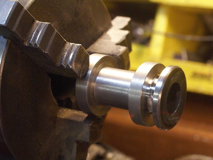
It took a bit of experimentation to get a feel for how much the jaws moved when adjusted, but my trusty Dial indicator and DTI soon had the 1 inch Drill Rod centered and then properly offset for cutting the specified dimensions. The cutting began with the long 6 inch shaft section. I've seen photos of any number of crashed crankshaft projects, so I wanted all the support I could get on the chuck end of things. That long shaft looked much longer when the cutting tool began to draw first blood.
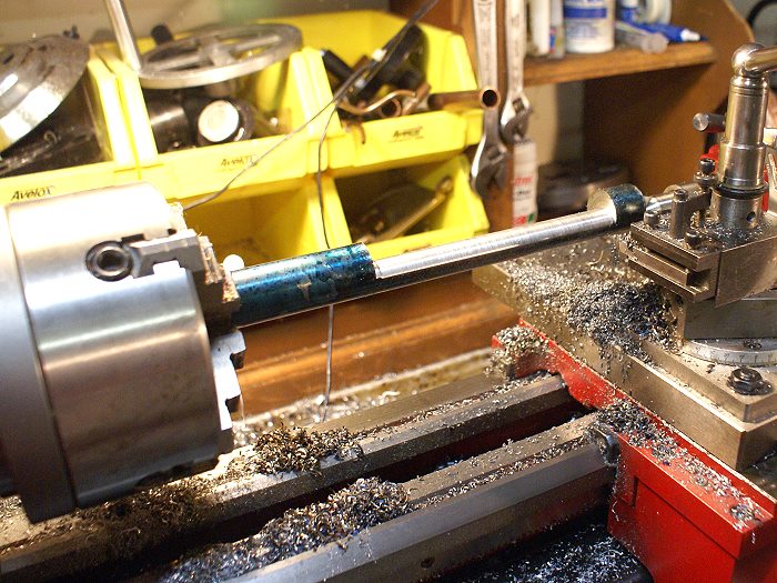
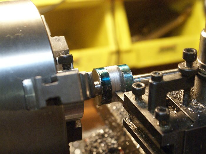
Interrupted cuts can be a little unpredictable, even when working in close to the chuck. Step out a ways from that safe haven and things can go pear shaped real fast and real bad if you get too aggressive. I kept the cuts fairly light until the interrupt was down to a minimum. I can tell you there was a sigh of relief when the cutter stopped thumping and began cutting a nice smooth 1/2 inch round shaft.
It's always good to spot a moment where things are still fixable. This photo shows just such a moment. With plenty of metal yet to be removed to reach the .375 goal, I stopped off the machine and broke out the Micrometer to check the setup for any taper. All was well with a measured taper of .0013. Still time to make a correction if needed, however I chose to leave the problem for the polishing stage that would come later.
Once the long section was turned down to dimension, the short section near the chuck was undertaken. It was a much more stable work zone and the cut went quickly. I learned that the dials on this lathe are a lot more trust worthy than my smaller one. Less backlash and the additional mass greatly add to the confidence levels.
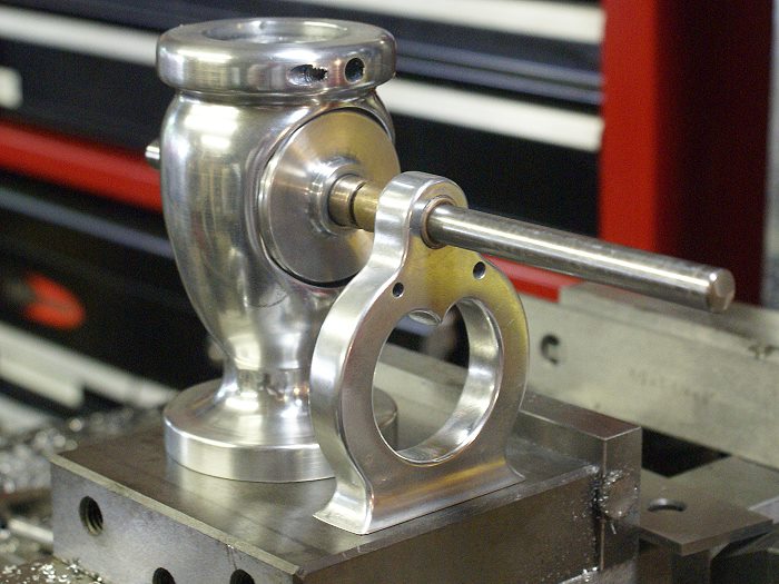
Once removed from the lathe, a quick trip to the bad saw removed the large end pieces so the shaft could be test fitted to the Engine body and the support. This also allowed me to prove my modifications would still work in the blind well described earlier in thus thread. The good news is all things are as the should be. The crank lobes have close but adequate clearance and the two bushings are dead on.
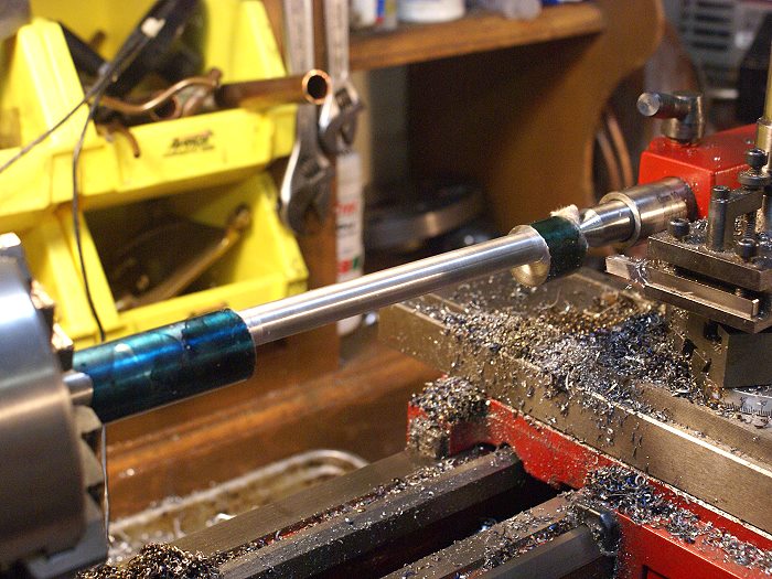
The next cut began with me holding my breath. The interrupted cuts were taken in light passes until things began to decrease in violence. The thin shafts were not making me feel any better about my chances of success, but I kept cutting, thinking each pass could be the one that turned things into a pretzel. Here is my solution to the problem.
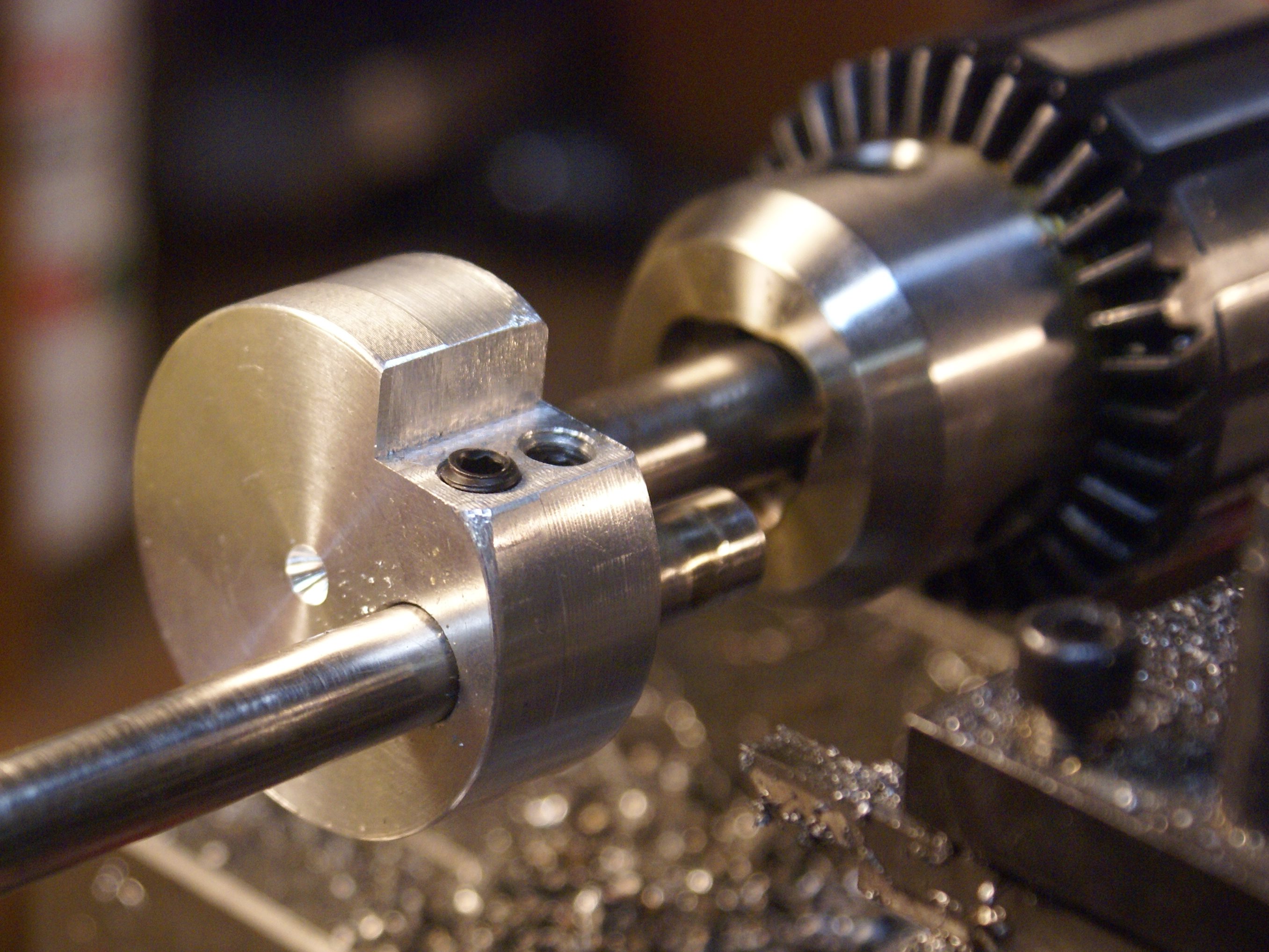
Since the shafts on this crank were so long, I chose to use a trick I learned on this board some time ago. Rather than try to trust the project to the 4 jaw and end up with no way to support the long section, I made up an offset turning jig so that I could work close to the chuck and still keep the other end supported. this would give me a bit more stability which would hopefully prevent a crash and burn. I would be working within a confined space, not too different from doing a cut off and making some potentially nasty interrupted cuts with a lot less metal keeping things together.
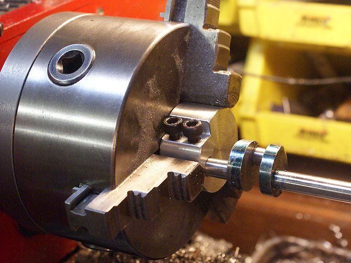
The jig was made on the mill and the hole was placed at .500 from the center. The screws were added to lock things down and worked like a champ. The long end was supported with a similar jig which I center drilled to give the center a purchase and prevent any chance of the end whipping about under the stress of the thumping and bumping such a cut creates. The screws have small brass tabs to prevent the shaft from being scarred.
Once again the loss of the infernal thumping signaled that the cutter was now past the gap and cutting a nice smooth round. The sense of relief was strong as I began to move in on the desired dimension of .375.

A bit of filing edges and some clean up on the lathe were then the order of the hour. The crank looked cool inside the engine body and proved to be completely usable as modified.... so far....(grin).
Steve
I needed a crank shaft and this Duclos guy said it needed to be a solid one piece version. To make things even more challenging, I've decided to add a couple of items to his design, one of which the motor will need to drive. This meant instead of ending up with an abbreviated "L" shaped crank, I'd be making a more difficult but more conventional -U- type with a one inch throw. Did I mention that one length of the shaft on this thing is nearly a full 6 inches long or that it has to align within .001 across 3 different bushings?
Since I had exactly no hot roll flat stock, I wound up using a 1 inch piece of Drill Rod....Silver Steel, for you UK guys. The long shafts would have to be turned to .375 +.002/-.000. so we're talking seemingly endless interrupted cuts over a nearly 10 inch steel rod, with no going over the mark allowed. No pressure..... for a first time attempt..... eh?
After a bit of head scratching, I broke out the dreaded 4 jaw chuck. In fairness, I only dreaded the 4 jaw because it was so difficult to change over when I was using the mini lathe. I'd learned any number of work around tricks to avoid the hassles of installation. The new C4 lathe has adequate room to easily access the chuck so that excuse was no longer valid. I decided to conquer my bias and get used to using the darned thing.
It took a bit of experimentation to get a feel for how much the jaws moved when adjusted, but my trusty Dial indicator and DTI soon had the 1 inch Drill Rod centered and then properly offset for cutting the specified dimensions. The cutting began with the long 6 inch shaft section. I've seen photos of any number of crashed crankshaft projects, so I wanted all the support I could get on the chuck end of things. That long shaft looked much longer when the cutting tool began to draw first blood.
Interrupted cuts can be a little unpredictable, even when working in close to the chuck. Step out a ways from that safe haven and things can go pear shaped real fast and real bad if you get too aggressive. I kept the cuts fairly light until the interrupt was down to a minimum. I can tell you there was a sigh of relief when the cutter stopped thumping and began cutting a nice smooth 1/2 inch round shaft.
It's always good to spot a moment where things are still fixable. This photo shows just such a moment. With plenty of metal yet to be removed to reach the .375 goal, I stopped off the machine and broke out the Micrometer to check the setup for any taper. All was well with a measured taper of .0013. Still time to make a correction if needed, however I chose to leave the problem for the polishing stage that would come later.
Once the long section was turned down to dimension, the short section near the chuck was undertaken. It was a much more stable work zone and the cut went quickly. I learned that the dials on this lathe are a lot more trust worthy than my smaller one. Less backlash and the additional mass greatly add to the confidence levels.
Once removed from the lathe, a quick trip to the bad saw removed the large end pieces so the shaft could be test fitted to the Engine body and the support. This also allowed me to prove my modifications would still work in the blind well described earlier in thus thread. The good news is all things are as the should be. The crank lobes have close but adequate clearance and the two bushings are dead on.
The next cut began with me holding my breath. The interrupted cuts were taken in light passes until things began to decrease in violence. The thin shafts were not making me feel any better about my chances of success, but I kept cutting, thinking each pass could be the one that turned things into a pretzel. Here is my solution to the problem.
Since the shafts on this crank were so long, I chose to use a trick I learned on this board some time ago. Rather than try to trust the project to the 4 jaw and end up with no way to support the long section, I made up an offset turning jig so that I could work close to the chuck and still keep the other end supported. this would give me a bit more stability which would hopefully prevent a crash and burn. I would be working within a confined space, not too different from doing a cut off and making some potentially nasty interrupted cuts with a lot less metal keeping things together.
The jig was made on the mill and the hole was placed at .500 from the center. The screws were added to lock things down and worked like a champ. The long end was supported with a similar jig which I center drilled to give the center a purchase and prevent any chance of the end whipping about under the stress of the thumping and bumping such a cut creates. The screws have small brass tabs to prevent the shaft from being scarred.
Once again the loss of the infernal thumping signaled that the cutter was now past the gap and cutting a nice smooth round. The sense of relief was strong as I began to move in on the desired dimension of .375.
A bit of filing edges and some clean up on the lathe were then the order of the hour. The crank looked cool inside the engine body and proved to be completely usable as modified.... so far....(grin).
Steve

$17.90
$24.95
Backyard Building: Treehouses, Sheds, Arbors, Gates, and Other Garden Projects (Countryman Know How)
Amazon.com


$94.99
$109.99
AHS Woodmaster 4400 Maintenance Kit for Outdoor Wood Boiler Treatment
Alternative Heating & Supplies


$39.99
$49.99
Sunnytech Low Temperature Stirling Engine Motor Steam Heat Education Model Toy Kit For mechanical skills (LT001)
stirlingtechonline


$180.50
$190.00
Genmitsu CNC 3018-PRO Router Kit GRBL Control 3 Axis Plastic Acrylic PCB PVC Wood Carving Milling Engraving Machine, XYZ Working Area 300x180x45mm
SainSmart Official


$519.19
$699.00
FoxAlien Masuter Pro CNC Router Machine, Upgraded 3-Axis Engraving All-Metal Milling Machine for Wood Acrylic MDF Nylon Carving Cutting
FoxAlien Official

$39.58
$49.99
Becker CAD 12 3D - professional CAD software for 2D + 3D design and modelling - for 3 PCs - 100% compatible with AutoCAD
momox Shop

$29.95
Competition Engine Building: Advanced Engine Design and Assembly Techniques (Pro Series)
Amazon.com Services LLC


$89.99
Outdoor Wood Boiler Water Treatment Rust Inhibitor- AmTech 300 & Test Kit
Alternative Heating & Supplies


$99.99
AHS Outdoor Wood Boiler Yearly Maintenance Kit with Water Treatment - ProTech 300 & Test Kit
Alternative Heating & Supplies


![DreamPlan Home Design and Landscaping Software Free for Windows [PC Download]](https://m.media-amazon.com/images/I/51kvZH2dVLL._SL500_.jpg)
$0.00
DreamPlan Home Design and Landscaping Software Free for Windows [PC Download]
Amazon.com Services LLC

$45.99
Sunnytech Mini Hot Air Stirling Engine Motor Model Educational Toy Kits Electricity HA001
stirlingtechonline


$25.34
$34.99
Bowl Sander Tool Kit w/Dual Bearing Head & Hardwood Handle | 42PC Wood Sander Set | 2" Hook & Loop Sanding Disc Sandpaper Assortment | 1/4" Mandrel Bowl Sander for Woodturning | Wood Lathe Tools
Peachtree Woodworking Supply Inc


Cedge
Well-Known Member
- Joined
- Jul 12, 2007
- Messages
- 1,727
- Reaction score
- 28
Thanks guys.... having you looking over my shoulder is actually helping the project along.
Kevin
The long shaft was turned at speed ranging from 100 at the start to 150 rpm as things began to smooth out. The independent power feed was a real blessing since it took quite a number of light passes to keep it all from going pear shaped. The journel cut actually went pretty well with beginning a speed 125 rpm and finishing up around 250.
Bob
I cant take credit for the jig idea. It was posted here on the board long ago. My only additional contribution was the tail stock support. It was actually easy to align since the work piece was mounted solidly in the chuck. All I had to do is leave the screws loose on the shaft and line up the center drilled hole with the dead center point. Then I gently secured it and checked the shaft with my dial indicator to make sure all was straight. I might have just been lucky, but I didn't have to readjust it.
Itow....
I thought about making several up to accept different sizes of cranks, but then it dawned on me that as many as I might try to cover, the next one I make would probably not be a size I'd planned for. I'll just make them as I need them.
I took tonight off and went to a minor league baseball game. What a waste... all I did was sit there thinking about how I was going to mod the con rod that the extra crank section will require....(grin)
Steve
Cedge
Well-Known Member
- Joined
- Jul 12, 2007
- Messages
- 1,727
- Reaction score
- 28
I'm still simmering the ideas on the con rod, but it hasn't slowed progress on the engine. There are plenty of parts to make while I'm finalizing it's design.
Having met some local model machinists of recent, I learned one of them likes cutting gears. I approached him about the gears for this engine and he's agreed to cut them if I supply him with required gear blanks. Hopefully we'll get together later this week and I can learn a bit about it.
The instructions for the Victorian give information based on ordered gears and fitting a cam ring to them, however Duclos hinted at making a single piece cam/gear if once could cut one's own gears. With that in mind, I took off in that direction.
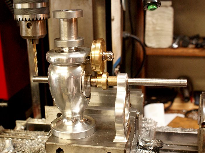
The gear blanks were first turned on the lathe to match the given specs. I chose to use brass instead of steel for visual contrast against the aluminum. I needed one with 56 teeth at 1 13/16 diameter and another at 15/16 diameter with 28 teeth.
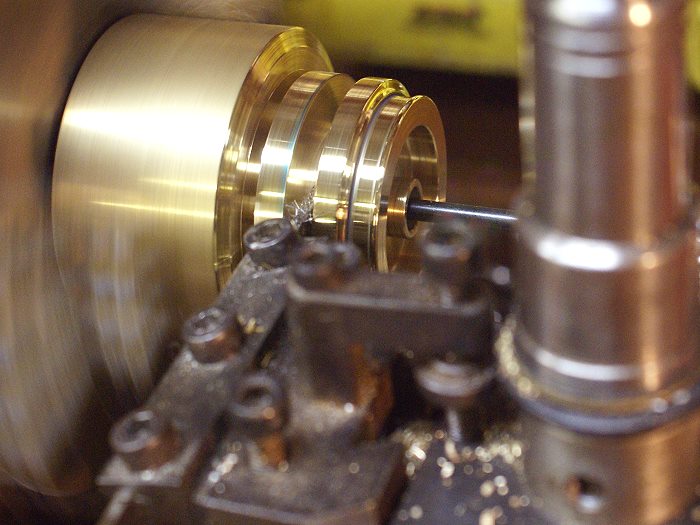
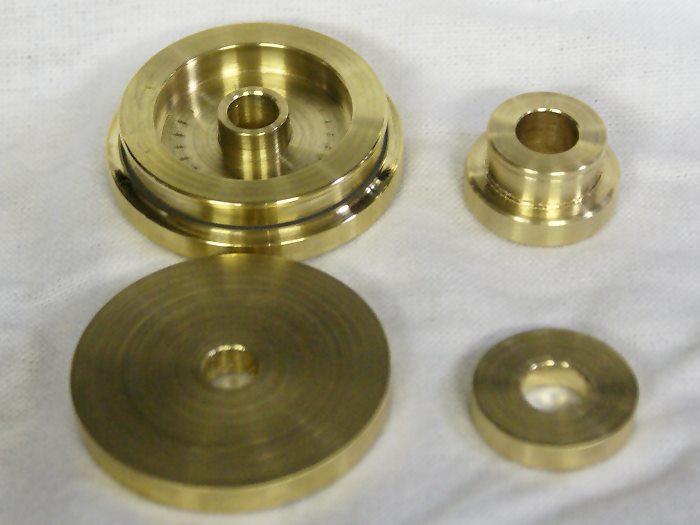
After carefully hitting the required diameter for both sizes, the larger blank was moved top the mill and securely placed on the manual rotary table. Now how does one cut a 247 degree arc on a manual indexing tool? DRO to the rescue. The piece was centered and the first cam ramp was to be milled at the "Zero" angle on a given radius. To do this, I asked the DRO to create a bolt circle with a beginning point of 0°. Once the first ramp point was milled, I then asked for another bolt circle with a beginning point of 247° at the same radius. I couldn't have asked for easier and I learned something new.
The results can be seen in the photo below. The points were gently milled to round the edges and a file smoothed it all out. A roller will follow the inner circle and will actuate a lever when it rides up on the raised came section. This will eventually control the exhaust valve on the engine
Again, everything gets a test fitting. The bushings will be getting trimmed and once the teeth are on the gear blanks they will mesh for alignment. Things seem to be moving relatively quickly on this project right now, but I'm keeping all my fingers crossed.
Steve
Having met some local model machinists of recent, I learned one of them likes cutting gears. I approached him about the gears for this engine and he's agreed to cut them if I supply him with required gear blanks. Hopefully we'll get together later this week and I can learn a bit about it.
The instructions for the Victorian give information based on ordered gears and fitting a cam ring to them, however Duclos hinted at making a single piece cam/gear if once could cut one's own gears. With that in mind, I took off in that direction.
The gear blanks were first turned on the lathe to match the given specs. I chose to use brass instead of steel for visual contrast against the aluminum. I needed one with 56 teeth at 1 13/16 diameter and another at 15/16 diameter with 28 teeth.
After carefully hitting the required diameter for both sizes, the larger blank was moved top the mill and securely placed on the manual rotary table. Now how does one cut a 247 degree arc on a manual indexing tool? DRO to the rescue. The piece was centered and the first cam ramp was to be milled at the "Zero" angle on a given radius. To do this, I asked the DRO to create a bolt circle with a beginning point of 0°. Once the first ramp point was milled, I then asked for another bolt circle with a beginning point of 247° at the same radius. I couldn't have asked for easier and I learned something new.
The results can be seen in the photo below. The points were gently milled to round the edges and a file smoothed it all out. A roller will follow the inner circle and will actuate a lever when it rides up on the raised came section. This will eventually control the exhaust valve on the engine
Again, everything gets a test fitting. The bushings will be getting trimmed and once the teeth are on the gear blanks they will mesh for alignment. Things seem to be moving relatively quickly on this project right now, but I'm keeping all my fingers crossed.
Steve
Cedge
Well-Known Member
- Joined
- Jul 12, 2007
- Messages
- 1,727
- Reaction score
- 28
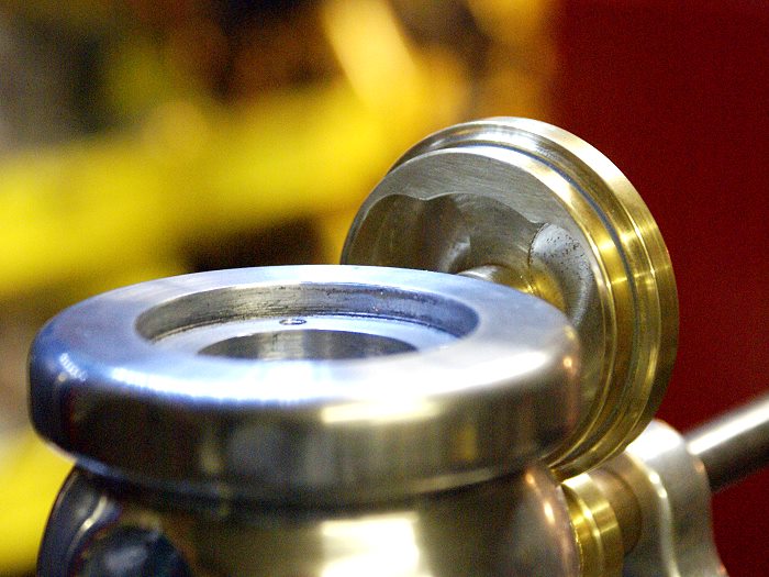
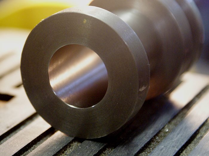
The Victorian project begins to take on the look of an engine as the cylinder is fitted to the base. The cylinder will be water cooled, so there will be a water jacket yet to be fitted to the outer flanges.
Turning the cylinder was pretty straight forward, although cutting the Durabar gray cast iron took a bit of experimenting to find out what the metal liked. I found a sharp HSS cutter and low RPM gave me the best results. Chatter was a bit of a bear in the confined area of the lower neck, but file finishing the cast iron was easy and rendered up a nice contour.
Even with a good set of boring bars, the bore of the cylinder will have tiny ridges that will create friction and wear on the piston rings. In order to prevent this, lapping the bore is a must. I used a softer metal for the lapping hone, in this case, copper being the metal of choice. The bore of the cylinder is .750 inches so the 5/8 copper plumbing pipe made a convenient sized lap and was long enough to give good control. It is an inexpensive section of repair pipe from the local Ace Hardware store and a handy source of copper for various other uses as well.
The abrasive I used is a metal polish containing microscopic grit called MAAS. I've used it for finish polishing metals ranging from aluminum and brass to cast iron and stainless with excellent results.
By running the lathe at about 400 RPM and keeping the lap moving at all times, the bore quickly smoothed out. The copper pipe felt as if the bore had huge ridges, even though none were visible. As these invisible ridges disappeared, the copper lap began to feel silky smooth, as I moved it back and forth within the bore. A thorough cleaning to remove any remaining grit followed and is a step not to be skipped.
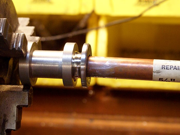
Here is the final product of the lapping process. It took less than 10 minutes and will give the cast iron piston rings a nice even surface upon which to seat.
As I said before, its beginning to look a little more like an engine and less like a steam punk funeral urn...(grin)
Steve
Turning the cylinder was pretty straight forward, although cutting the Durabar gray cast iron took a bit of experimenting to find out what the metal liked. I found a sharp HSS cutter and low RPM gave me the best results. Chatter was a bit of a bear in the confined area of the lower neck, but file finishing the cast iron was easy and rendered up a nice contour.
Even with a good set of boring bars, the bore of the cylinder will have tiny ridges that will create friction and wear on the piston rings. In order to prevent this, lapping the bore is a must. I used a softer metal for the lapping hone, in this case, copper being the metal of choice. The bore of the cylinder is .750 inches so the 5/8 copper plumbing pipe made a convenient sized lap and was long enough to give good control. It is an inexpensive section of repair pipe from the local Ace Hardware store and a handy source of copper for various other uses as well.
The abrasive I used is a metal polish containing microscopic grit called MAAS. I've used it for finish polishing metals ranging from aluminum and brass to cast iron and stainless with excellent results.
By running the lathe at about 400 RPM and keeping the lap moving at all times, the bore quickly smoothed out. The copper pipe felt as if the bore had huge ridges, even though none were visible. As these invisible ridges disappeared, the copper lap began to feel silky smooth, as I moved it back and forth within the bore. A thorough cleaning to remove any remaining grit followed and is a step not to be skipped.
Here is the final product of the lapping process. It took less than 10 minutes and will give the cast iron piston rings a nice even surface upon which to seat.
As I said before, its beginning to look a little more like an engine and less like a steam punk funeral urn...(grin)
Steve
hitandmissman
Well-Known Member
That is coming along great and will make a fine addition to your collection.
Cedge
Well-Known Member
- Joined
- Jul 12, 2007
- Messages
- 1,727
- Reaction score
- 28
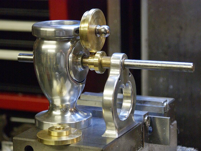
Things have been moving along nicley and I'm learning all sorts of new things from this project. The Victorian requires a pair of spur gears with a ratio of 2:1. I considered several options to supply them and friends like Tim (Zuesrekining) graciously offered their help, if needed. The options ranged from a simple online order (to easy) to having a local friend cut them (involute cutters are damned expensive). I finally chose to cut my own gears using Duclos' instructions for single tooth cutting technique. Thanks go to George Seal for pointing me to the references in his first book.
I recently acquired a small rotary table, complete with an indexing plate, neither of which I've used until now. It's too small for much serious work, but the MT2 taper was perfect for using my tail stock drill chuck to hold a mandrel, so onto the mill table it went. Things were a little crowded with both the vise and the RT, but it was workable.
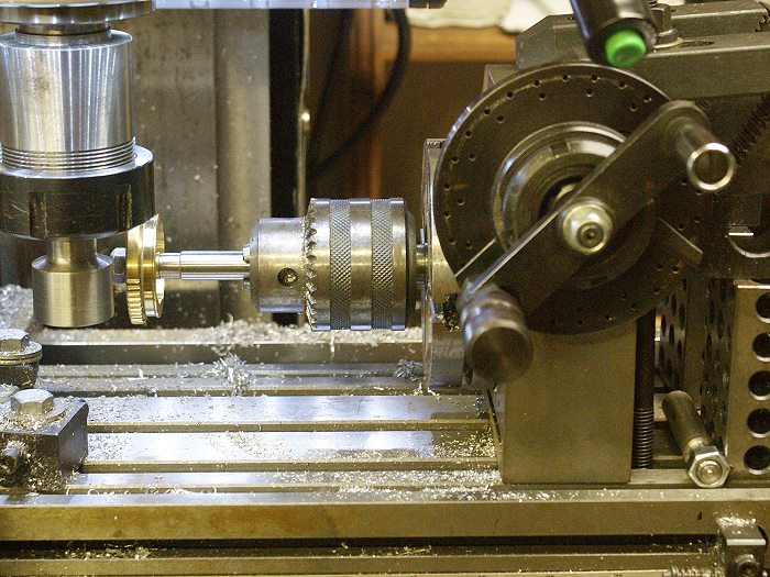
After cutting a practice gear in aluminum, it was time to get serious. The cam gear blank was mounted and the first cut was begun. It would require several passes of 56 cuts, so patience was the order of the day. The tiny cutter is shown mounted in the flat angle fly cutter I made up to hold the tool. The blank has just begun to receive the first round of cuts. The cutter mimics an involute cutter but is less critical than required for the high level of accuracy of what are rather expensive commercial cutters. (one quote was $120.00 for the needed pair)
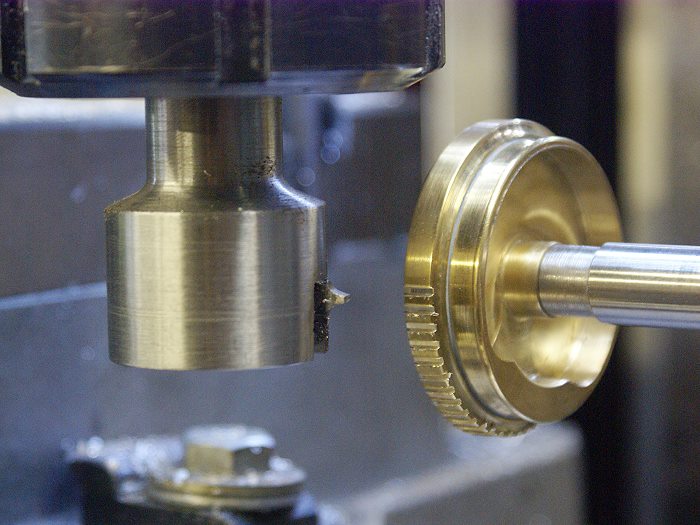
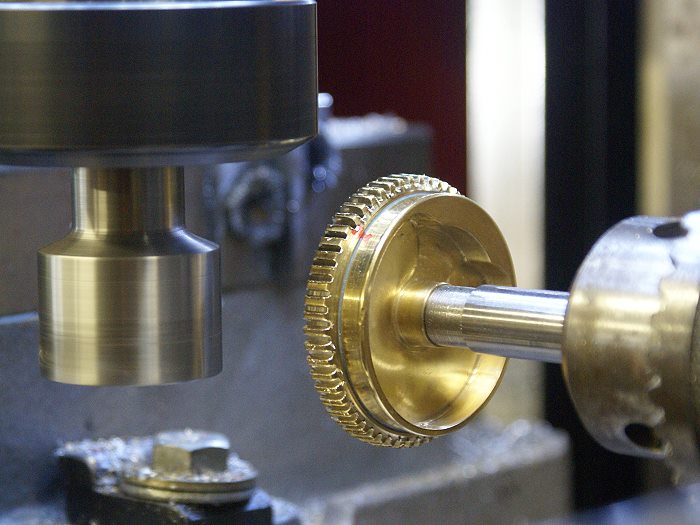
As thing progressed, making the gears was proving to be feasible. The photo below shows the gear getting it's second pass. There were two gears to cut, one with 56 teeth and another with 28.
The gears were on and off the mill several times for testing and then returned to fine tune the cuts. I mentioned patience.... the excitement sags a bit after 5 or 6 times around a 56 tooth gear. The routine of make a cut, reset the hole count scissors on the RT, lock out the indexing pin, count off the complete turns and then settle the indexing pin in its new hole.... well you get the picture.
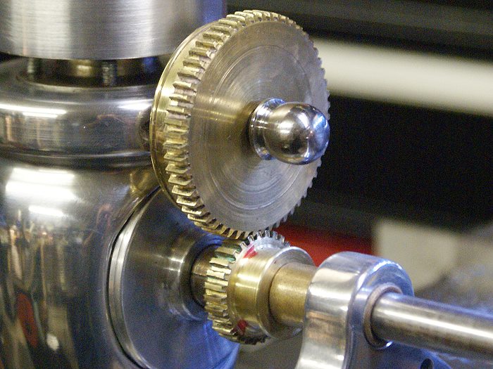
Here is the almost final test fitting. I say final because this is where the first required remake of a part came about. Just after this photo was taken I moved the small gear back to the mill to take off another .003 inches to chase away the last of the binding between the pair. 3/4 of the way around the blank I managed to drop count on the completed turns of the RT and planted the cutter dead center of a tooth. Scratch one gear. It was SOOOOOOoooooo close to being finished. Nope.... no throwing, but I did vent a bit. At least it wasn't the cam gear. That one would have really hurt. Tomorrow, I'll cut a new blank and go back at it.
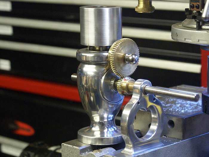
The photo below shows the gears and the cylinder's new water jacket. (thanks Tim... your help with the arbor press was a life saver) The cylinder head is likely to be the next major project, along with the piston and the idea I've gotten for con rod.
Steve
I recently acquired a small rotary table, complete with an indexing plate, neither of which I've used until now. It's too small for much serious work, but the MT2 taper was perfect for using my tail stock drill chuck to hold a mandrel, so onto the mill table it went. Things were a little crowded with both the vise and the RT, but it was workable.
After cutting a practice gear in aluminum, it was time to get serious. The cam gear blank was mounted and the first cut was begun. It would require several passes of 56 cuts, so patience was the order of the day. The tiny cutter is shown mounted in the flat angle fly cutter I made up to hold the tool. The blank has just begun to receive the first round of cuts. The cutter mimics an involute cutter but is less critical than required for the high level of accuracy of what are rather expensive commercial cutters. (one quote was $120.00 for the needed pair)
As thing progressed, making the gears was proving to be feasible. The photo below shows the gear getting it's second pass. There were two gears to cut, one with 56 teeth and another with 28.
The gears were on and off the mill several times for testing and then returned to fine tune the cuts. I mentioned patience.... the excitement sags a bit after 5 or 6 times around a 56 tooth gear. The routine of make a cut, reset the hole count scissors on the RT, lock out the indexing pin, count off the complete turns and then settle the indexing pin in its new hole.... well you get the picture.
Here is the almost final test fitting. I say final because this is where the first required remake of a part came about. Just after this photo was taken I moved the small gear back to the mill to take off another .003 inches to chase away the last of the binding between the pair. 3/4 of the way around the blank I managed to drop count on the completed turns of the RT and planted the cutter dead center of a tooth. Scratch one gear. It was SOOOOOOoooooo close to being finished. Nope.... no throwing, but I did vent a bit. At least it wasn't the cam gear. That one would have really hurt. Tomorrow, I'll cut a new blank and go back at it.
The photo below shows the gears and the cylinder's new water jacket. (thanks Tim... your help with the arbor press was a life saver) The cylinder head is likely to be the next major project, along with the piston and the idea I've gotten for con rod.
Steve
ChooChooMike
Well-Known Member
- Joined
- Jan 5, 2008
- Messages
- 863
- Reaction score
- 13
WOW !! Robert Kipp has some beautiful engines shown on that page !! :bow:cfellows said:Here's a link to a picture of the Victorian built by Robert Kipp and displayed at GEARS in 2006. The Victorian is in the second row on the left.
http://216.197.127.227/Gallery/exhibitorpages/kipp.html
Here's the Victorian image :

I love the Fairbanks Morse one too :

Similar threads
- Replies
- 3
- Views
- 460