Opposed Twin I.C.

Home Model Engine Machinist Forum

Help Support Home Model Engine Machinist Forum:

This site may earn a commission from merchant affiliate links, including eBay, Amazon, and others.
Brian,
I may look at it wrong but it appears to me as if there is a slight misalignment of the angle piece at the upper corner facing towards the viewer when looking at the picture?

Peter J.
 
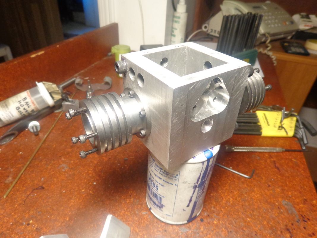
Peter-It's not your eyes. I haven't completely finished the two pieces yet. They are machined and bolted together, but I still have to take a very light "squaring cut" to make all sides square and parallel. The problem with making pieces like this in a milling vice is that the jaws always "cock up" one or two degrees when closed under pressure, and the results quite often are what you see. For a squaring cut" the assembly gets clamped to the mill table with a pair of toe clamps, which ensures that all faces end up square and parallel to each other.---Brian
 
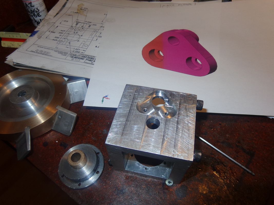
Yes, Me darlin's---Any progress is better than "dead in the water"!! I got hung up this afternoon waiting for information from a customer, so I spent my time making the big "bolt-on" crankshaft bushing and drilling/reaming/boring the engine housing to fit it. Don't take me to task to heavily for the finish on that big bolt on bushing. It was machined from a piece of "mystery metal" with a carbide cutting tool of dubious origin. (I was given a big handful of brazed carbide tooling by a fab shop that has switched over to carbide inserts.)---it isn't going to be visible anyways, as it hides behind my finned flywheel when all is assembled. I have a jar of oilite bushings left over from something, and that is what you see pressed into the center of the bolt on bushing. No, that isn't the crankshaft you see setting in there---It's just a short piece of 3/8" rod to make a better picture.
 
On the side of the frame opposite to the bolt in crankshaft bushing, I also wanted to have a "bolt in" camshaft bushing, large enough to let me pull the assembled camshaft out through the side of the frame. This results in some rather interesting milling, (than God for my DRO's). The sheet of paper laying in the background shows a model of what the cam bushing will look like. ----(scale is larger than the real deal, but it shows up better). The through hole in the frame is reamed to 0.5" diameter and the protrusion on the far side of the cam bushing will be 0.499" diameter. The reamed hole in the center of the red cam bushing is .375" diameter to match the outer diameter of the oilite bronze camshaft bushing. The odd shaped cavity in the frame will be clearance all around for the outer perimeter of the cam bushing, and the cam bushing will be held in place by two #8 shcs.
 
Last edited:
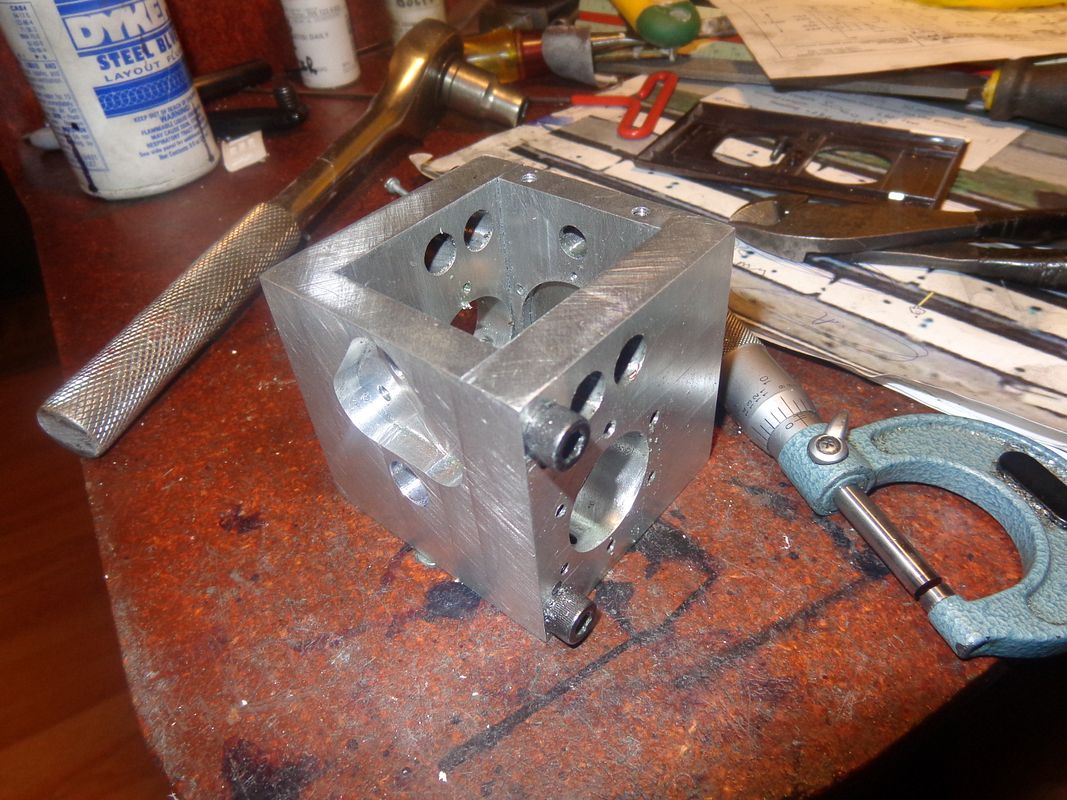
This has to be one of the busier pieces I have made. (Actually, it's two pieces bolted and doweled together). It has: 30 tapped holes, 4 clearance holes, 21 reamed holes, one bored hole, and one counterbored pocket. I THINK they are all in the right place. I have been very busy with design work, moving lathes, and repositioning electrical outlets and the associated drywall work to accommodate the new lathe in my tiny machine shop. The old green 10" x 18 BusyBee lathe and all its attachments has been sold and taken away to a new home in Toronto.
 
I don't plan on ever taking it apart. The crankshaft and the camshaft can be installed through the side of the frame. Hindsight being 20/20, if I had to do this over again, I would probably make it from a cube of aluminum. The only issue would have been cleaning out the rad in the four inside corners.
 
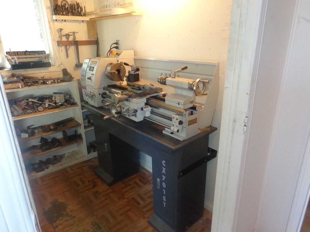
Out with the old----In with the new!!! The new CX701 lathe is installed in my machine shop ready for action. I had to relocate one electrical outlet and repair a bit of drywall, but other than that everything went very well. I have a piece of 2" x 1/8" mild steel bar welded into a U shape. It bolts to the studding in the wall and both ends are bolted to the cabinet which supports the lathe. The lathe is bolted through the catch pan and through the top sheet metal of the supporting cabinets. This just gives me that extra bit of security so I know that the lathe and stand is not going to ever fall over.
 
Years ago I made a rotary phase converter for my shop. I thought it would be nice to get the motor up off the floor so I bolted it into the wall. That turned the whole shop wall into a drumhead and the noise it made was unbelievable. it was back on the floor as fast as I could move it. I am not sure bolting tools to the wall is a good idea.
 
Ron---I find just the opposite. Being bolted to the stud walls in my basement actually makes my mill and lathe quieter.
 
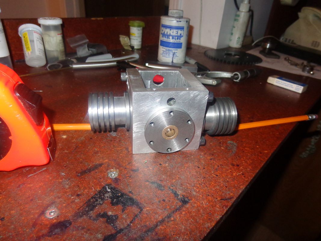
One cylinder machined this morning.--One more to go this afternoon!!! They are cast iron, not aluminum with a liner.
 
As my old father-in-law used to say "It ain't perfect, but it's damned close!!!" This project has been stalled for so long, I just had to take some time to do something for ME for a change. Today while I was working on the cylinders, another order for more "fixtures" came in so I know what I'll be doing the rest of the week, and it isn't working on my engine. It is very interesting to actually do some work on my new lathe. It is miles different from my older smaller lathe, and I will have to work with it quite a lot before I become comfortable with it. I did use the power feed to bring the cast iron down to correct diameter, and it certainly leaves a beautiful finish.
 
  • Like
Reactions: gus
After building a "Firefly 46" which came together very nicely, I had a desire to build a multi-
cylinder engine. So, a twin Firefly... a horizontally opposed two stroke, simultaneously firing.
Apparently very smooth and vibration free. I decided to fabricate the crankshaft, fitting the conrods during assembly .I think I might pin the crank-pins, just in case. This meant building a split crankcase with a rear bearing . I had an idea to install the needle valve in the back bearing plate. Anyway, so far so good ...

20151023_184942.jpg


20151023_185034.jpg
 
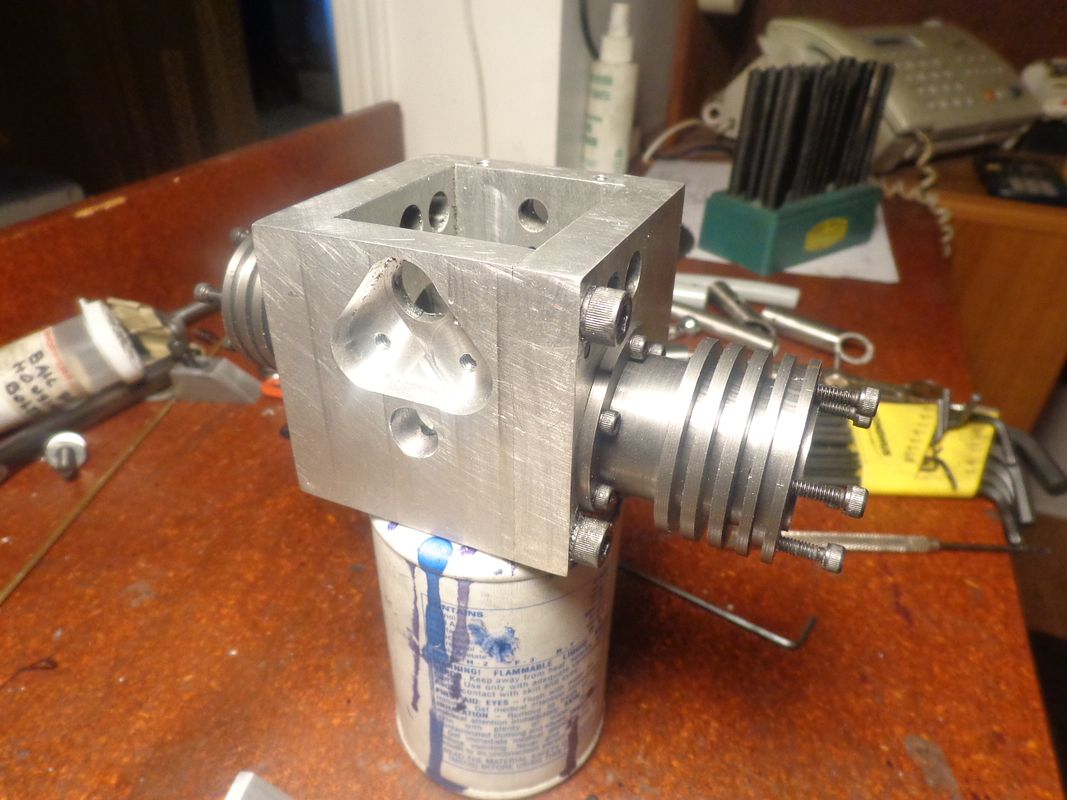
After what seems like an amazingly long time I finally got some time today to do a bit more work on my engine. I drilled all the clearance holes in the flanges which attach the cylinders to the "block" and installed the bolts. Everything bolted up the way I expected it to, and then I drilled the 10 holes (five in each cylinder) that get tapped #5-40 to hold the cylinder heads onto the cylinders. When I was tapping the eighth hole, the tap broke off at full depth flush with the top of the cylinder. --This caused a great deal of dismay as you can well expect, but after picking away at it for a while with no success, I chucked up a 1/16" carbide endmill and was able to mill out the tap and save the cylinder. I have a length of "stress proof" 1144 steel to make a one piece crankshaft from, and will probably make that my next order of business.
 
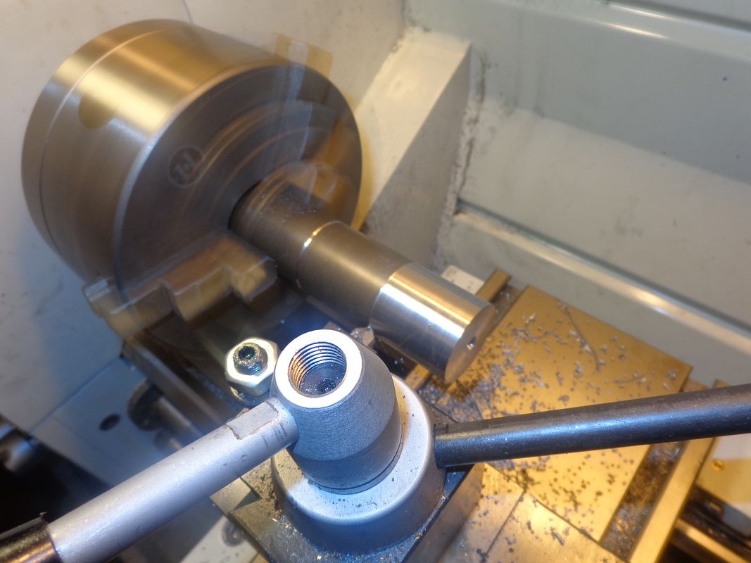
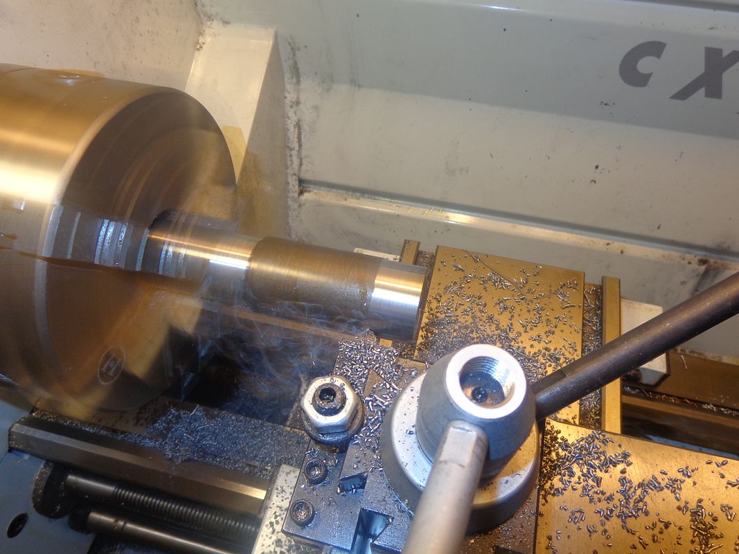
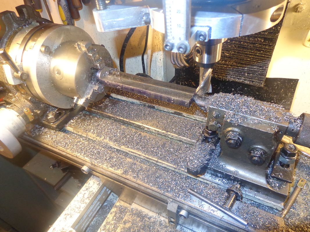
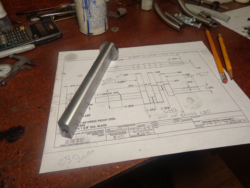
Today was "crankshaft madness day" at my house!! I wanted to buy a piece of 1 3/8" 1144 stress-proof to make my crankshaft from. 1144 is not available to buy in bars, only rounds.--and my supplier only had it in 1 1/2" diameter. The first two pictures show me reducing the stock from 1 1/2" diameter to 1.3" final diameter.--And yes, I did use the power feed for this operation, with an HSS cutter at 550 rpm. Also, in the same set-ups I put in the 60 degree countersink in each end so I can eventually turn the crankshaft between centers.

 
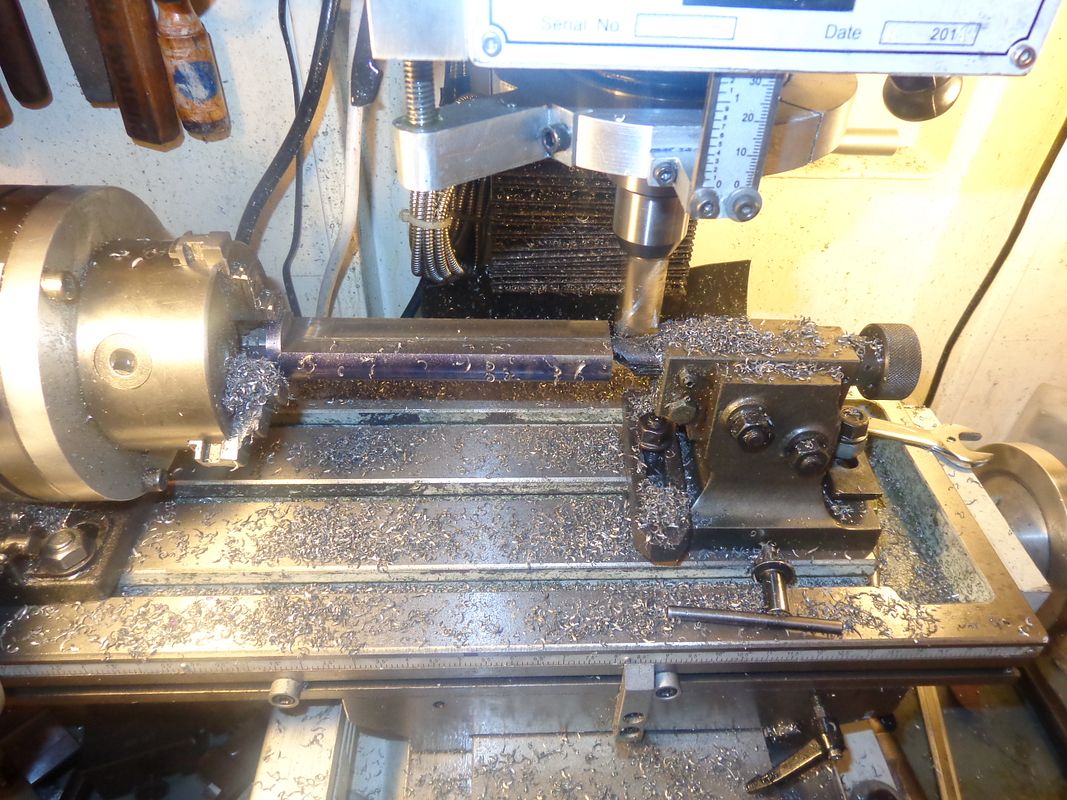
After turning the piece to 1.300" finished diameter, I had to get it from a round into a flat. I thought of various ways to cut away most of the slab from each side on my bandsaw, but any good way was going to involve me building some kind of fixture, so I decided to mill the excess material away. My thoughts in using the rotary table chuck to hold the part for this machining operation, along with the tailstock, was that this was probably the set-up that gave me the best hope of getting flat parallel surfaces and being able to flip the part over a true 180 degrees to machine the second side away. It worked, but at a .015" depth of cut there was a LOT of cranking involved. I have cut the blank to be 3/4" longer than the finished length of the crankshaft, so I figured I would probably be safe in holding 3/16" of the piece in the chuck on the rotary table, mounted on my mill.

 
All of the preceding operations have brought me to the point where I may actually be able to start machining the crankshaft. The first operation will be to put in two more countersunk holes in each end to provide a spot for turning the crank "throws" between centers.
 

Latest posts

Back
Top