Opposed Twin I.C.

Home Model Engine Machinist Forum

Help Support Home Model Engine Machinist Forum:

This site may earn a commission from merchant affiliate links, including eBay, Amazon, and others.
I am struggling to make my way through the cam timing, as originally determined by Malcolm Stride. This is exactly the timing diagram and valve profile as published for the Bobcat and Jaguar engines. I plan on using it for this new engine I am building. This is not easy to get my head around. I think I have 95% understanding after pouring through books published by Malcolm stride and L.C. Mason
 
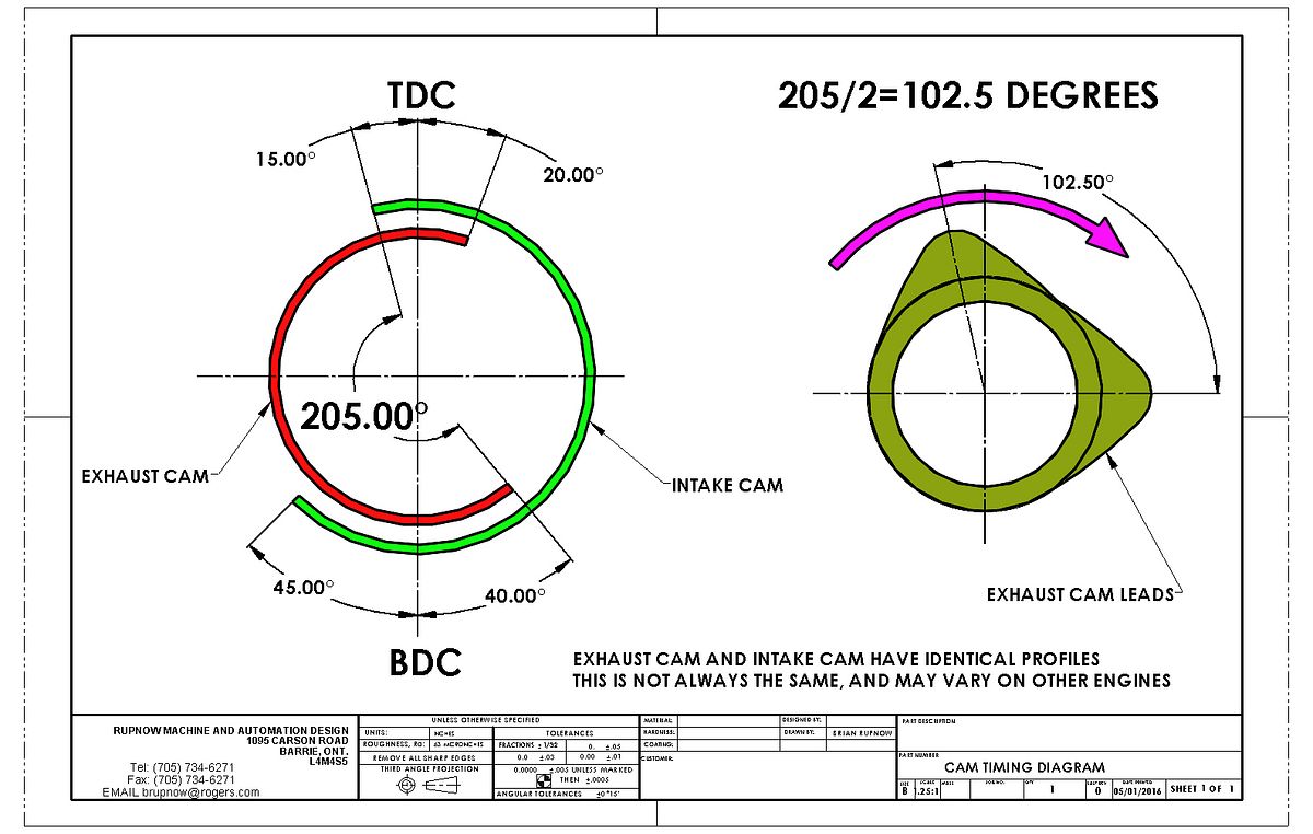
Now let me see if I can get my head around this. The piston is moving from top dead center to bottom dead center on the power stroke, with both valves closed. 40 degrees before bottom dead center, the exhaust cam which is leading begins to open the exhaust valve. Since there is a 1:2 relationship between crankshaft revolution and camshaft revolution, that translates to 20 degrees of camshaft rotation.
As the piston reaches bottom dead center and begins to travel up on the exhaust stroke, the exhaust valve stays open during the full upwards travel of the piston which represents 180 degrees of crankshaft rotation, or 90 degrees of camshaft rotation. Then as the piston reaches top dead center on the exhaust stroke, the exhaust valve stays open for 20 degrees of crankshaft rotation (10 degrees of camshaft rotation) during the intake stroke before it fully closes. This adds up to a total of 240 degrees of crankshaft rotation, or 120 degrees of camshaft rotation.
So—Let’s back up a little bit to where the piston is coming up to top dead center on the exhaust stroke with the exhaust valve wide open. 15 degrees of crankshaft rotation (7.5 degrees of camshaft rotation) before the piston reaches top dead center, the intake valve begins to open. It stays open thru the full intake stroke of the piston (180 degrees of crankshaft rotation, 90 degrees of camshaft rotation, and then as the piston reaches bottom dead center on the intake stroke and begins to move upward on the compression stroke, the intake valve stays open for an additional 45 degrees of crankshaft rotation, (22.5 degrees of camshaft rotation.)
This adds up to a total of 240 degrees of crankshaft rotation, (120 degrees of camshaft revolution).
So---we see that the exhaust cam and the intake cam must in this case have the same profile, since they must both be “active” an equal number of degrees of rotation. We also see that there is a total of 35 degrees of overlap at top dead center where both intake and exhaust valves are open at the same time.---this is typical of a “mid-range power/speed” engine. Hi speed/ hi-performance engines can have a greater overlap, while slower running engines must have a smaller overlap.
Now, there is a marvelous calculation used to position the intake and exhaust cams rotationally in respect to one and other. I have read this calculation enough times to make my head explode, and will repeat it here:
“Take the total of the valve open periods, divide by 2, subtract the total valve overlap and divide the result by 2”
So—the total of the valve open periods is 480 degrees of crankshaft rotation, divided by 2= 240 degrees.
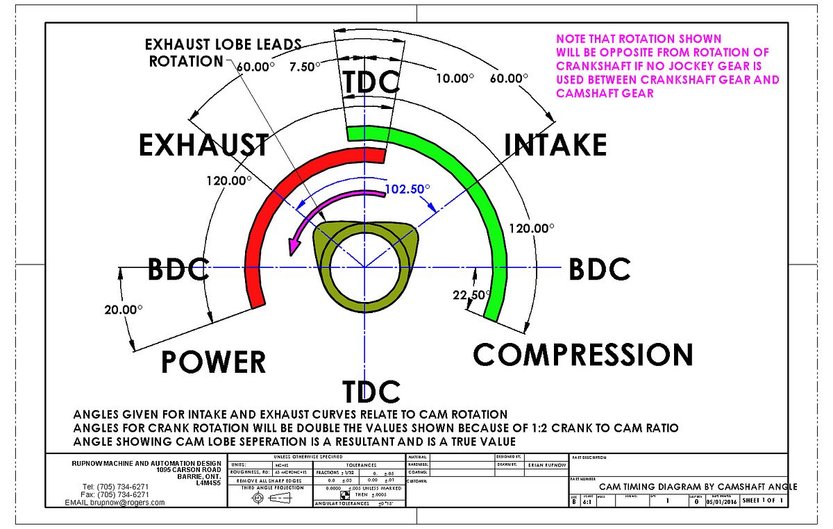
240 degrees -35 degrees of overlap=205 degrees. Then 205 divided by 2=102.5 degrees of rotational separation between the intake and exhaust cam lobes.
This information was gleaned from a number of sources, but primarily from information found in “Model Four Cycle Gasoline Engines” by C.L. Mason and in “Miniature Internal Combustion Engines” by Malcolm stride.
 
Here is another novel way of determining the cam lobe separation. I haven't seen it done this way before, but it works. This method presupposes that you know the lead and lag of the valves in relationship to the crankshaft so you can divide them by two and enter them as values for the camshaft, then by bisecting the curve and matching it to the centerline of the cam lobe it establishes what the cam lobe separation should be.
 
Looks to me as though you have mastered it. Had you not been intending to make all the cams at one go, I would have suggested a slightly fatter exhaust cam with an earlier opening would be more normal. It will probably make little difference in practice, as you probably won't be putting it on a dynamometer.
 
Brian; Thank you, thank you, thank you!!!Thm:Thm:Thm: I have been trying to get my head around this for quite a while and now you make it seem so simple.

Great build by the way. I may not say much in your posts but I do follow along on every one of them. I always seem to pick up some great nugget of information in each of them.

Ron
 
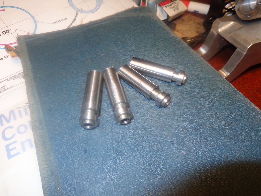
Not a lot of machining today. Spent too much time sussing out the mystery of cams and their rotational orientation to one an other. However, thanks to other forum members helping me, I think I have it mostly right now. I did prepare four cam "blanks" from 01 steel, turned to size and reamed to 1/4" to fit on the cam shaft. I gave up on my idea of milling all the cams at once because it was going to get a bit too complicated, so they will be milled using Cam Calc figures, and milling one at a time (Oh, my aching arthritic shoulder!!!). Oh well, I don't have to do them all in one day.
 
Here is another novel way of determining the cam lobe separation. I haven't seen it done this way before, but it works.

I like your 'cad' layout method. You can actually compute the resultant lobe separation & overlap numbers in a spreadsheet like I did (post #3) knowing intake/exhaust open/close inputs. But faking a cam layout visualization in Excel is a pita.
http://www.homemodelenginemachinist.com/showthread.php?t=21808

Where I see added value in your method is multi-cylinder engine design. I think your cam sketch can be copy transposed for remaining cylinders, adjust for their crankshaft layout/firing order & now the whole camshaft can be fully defined as all lobes are angularly related to one another or any arbitrary reference if you wanted to mill/grind a cam shaft.
 
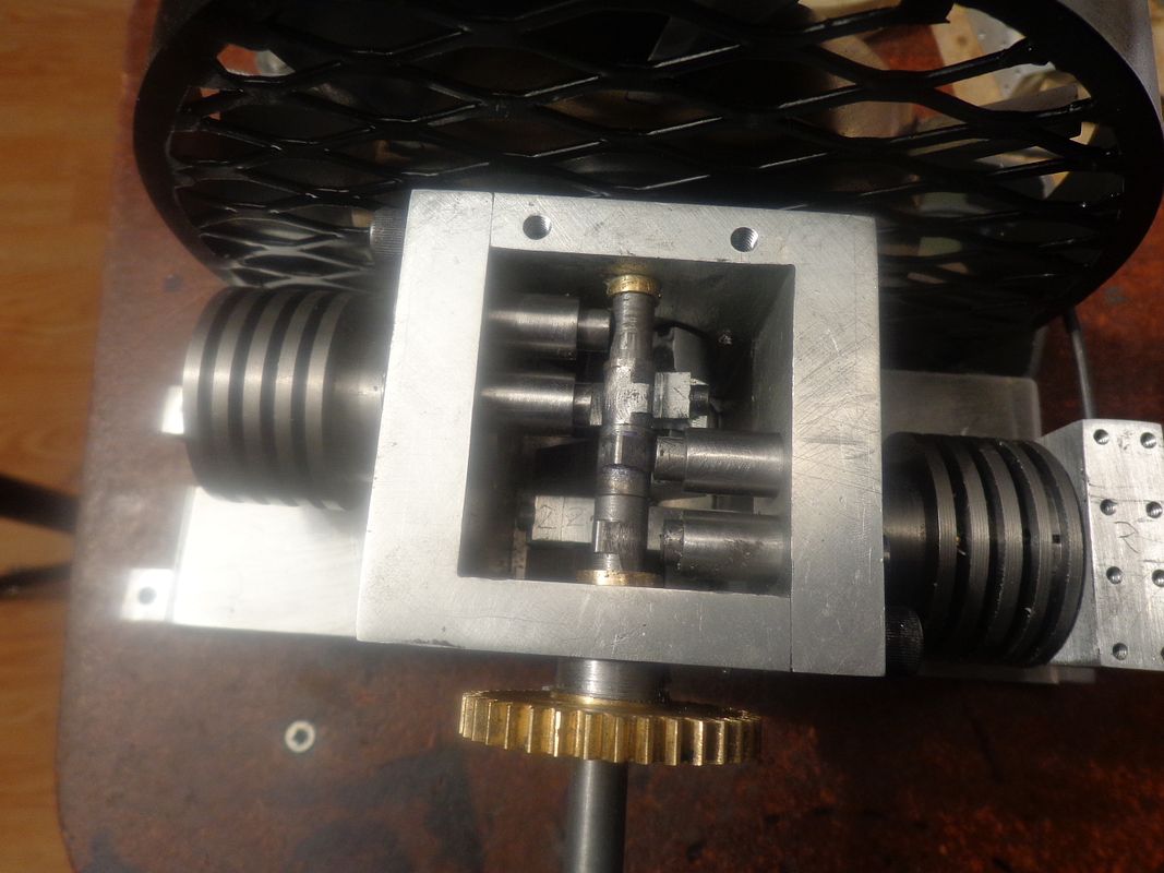
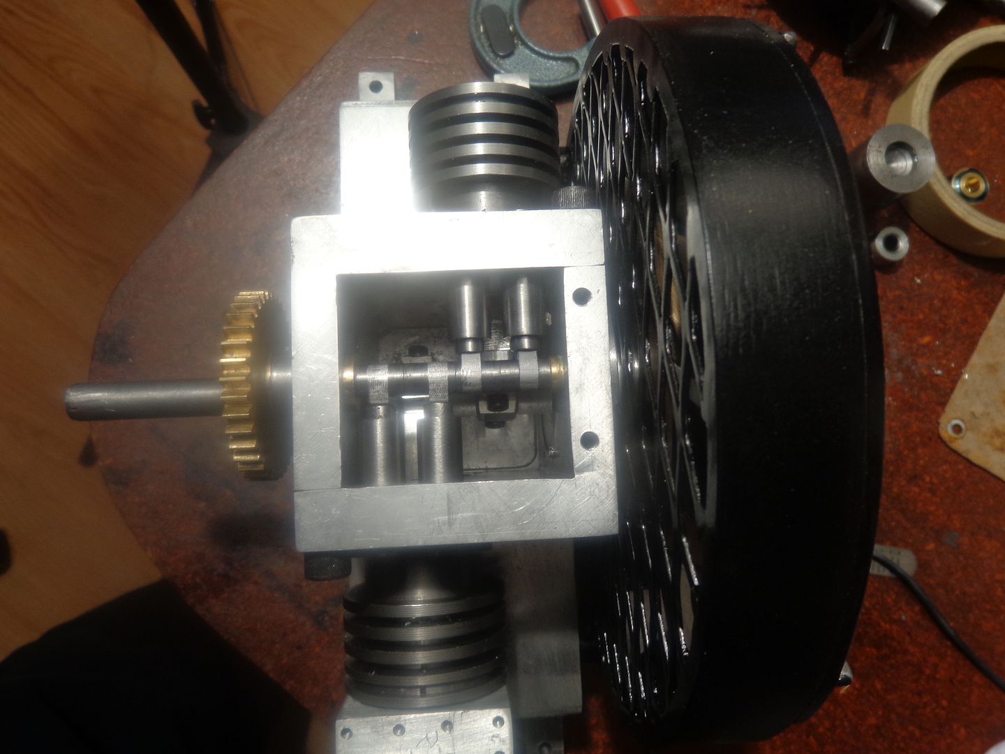
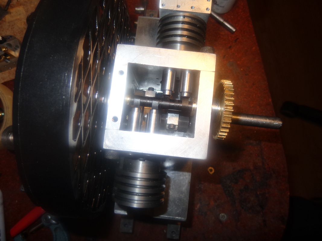
A rather crummy picture---but cam #1 is cut and setting in place. It still needs a bit of polishing and has to be hardened yet, but it is the first one and it fits. I don't do this cam making business often enough. After cutting this first one, I see that I COULD HAVE CUT ALL THE CAMS AT ONCE!!!----DAMN!!! Oh well, I'll remember now.
 
It's been an interesting and somewhat frustrating day. I made three cams. I actually started four cams, but had a brain fart on the second one and started feeding the endmill down instead of up---didn't realize it until about the fifteenth cut. I am not really happy with the finish on these cams. I moved the milling table back and forth in the Y axis to make these cams, and I'm wondering if that was a mistake. It seems to me that when I built other cams using this vertical mill method that I got a much better finish on them, but I may have been moving the table in the X axis when I made them.---I simply don't remember. The cams set right up on top of everything and are very visible, so I can't even hide them away deep in the bowels of the engine. EDIT--EDIT---I just went back and looked at my build thread for the original Malcolm Stride inspired "Canadian cub" and the cams were marvelously smooth, and they were machined by moving the table in the X axis.
 
Last edited:
-My mistake---I meant to say that I moved the table away from me and towards me while cutting the cams, which as I understand it is the Y axis. I have removed the "Z" from my previous post and replaced it with a "Y". The Z axis is the spindle movement.
 
Today I remade the cam as one long piece, all cam shaped. I moved the table of the mill right to left which is the X axis, and the finish was much, much better than the cams I made yesterday milling in the Y axis. I still have "miles to go before I sleep" on this, as the next step is to set it up in the lathe and turn down the areas which must be round and not cam shaped, and then part off 4 individual pieces. I'm still not sure if I'm "out of the woods" on this cam yet. I will post pictures if and when I get to something picture worthy.
 
Last edited:
Every so often, the good guys do win!!! Had a very breath holding, tongue biting morning, but everything parted off okay, and the cams all fit where they are supposed to. Now, if I can just flame harden them without melting them (they are pretty darned small) and get them Loctited to the shaft in the correct rotational aspect, we're away to the races!!!
 
Excellent work. So it is just the right time to pour a thimbleful of cold water over it! Brian, your tappets are too small. I am not absolutely sure, but I think you will find the cam riding on the edge of the tappet as it comes up the flank radius towards the nose radius. I am assuming a flat-faced tappet, if curved it's different. This line joining the flank and nose radii of the cam marks the maximum velocity of the valve, and the maximum dispacement of the contact point (line) from the centreline. The tappet should be of such a diameter that it covers this line across the full face width of the cam.
 
Charles--The tappets are exactly the same diameter as the tappets used on the Jaguar and Bobcat engine. The bottom of the tappet is flat, and the tappet is 1/4" diameter, while the cam itself is 0.157" wide. The cam has radiused flanks.The flame hardening and quench went well (I didn't melt nor distort the cams), and they all fit back onto the camshaft after being cleaned up a bit and degreased. I will Loctite the cam closest to the timing gears into place later today.
.
 
Last edited:
I have checked that geometry out with CAD (easier than doing the trigonometry) and it is "OK" by a fine hair's breadth. The contact line comes to within less that 0.003" from the edge of the tappet face, so it does not cover the full width of the cam, narrowing to less than 1/16 wide. For contact across the full width of the cam throughout, you would need a theoretical tappet diameter of 0.290". However, firstly this is the point at which the opening tappet starts to decelerate, so the forces are low, and secondly, it looks as though about half a thou. of total wear would produce a full contact width. Hope I have not caused undue alarm.
 
This has absolutely nothing to do with the current thread-----But---I went and seen the new Star Wars movie this afternoon.--My God---It was fabulous!!!--I loved the first 3 Star Wars movies, hated the second three Star Wars movies, and didn't really know what to expect with this newest release. Disney has bought the franchise from George Lucas, and they really did it right this time. This movie has everything that old sci-Fi buffs like myself love.--Okay, Okay---Back to more mundane things like engine building now.---Brian
 
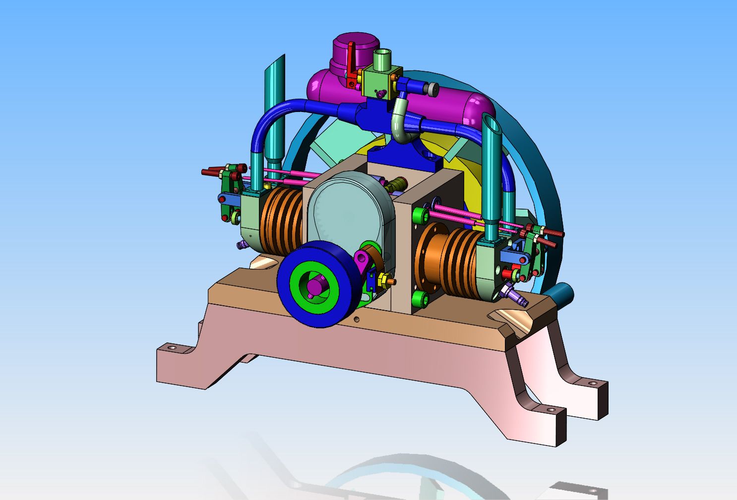
What to build, what to build next??? I can't do anymore with the valve train stuff until my bottle of #620 Loctite comes in to assemble the valve cages into the cylinder heads. Probably a good a place as any is the exhaust stacks. In the original model, I had faked in a pair of intake manifolds in the position of the exhaust stacks. I like the vertical stacks as shown here, and I like the angle cut ends on them, although that is purely a cosmetic thing.
 
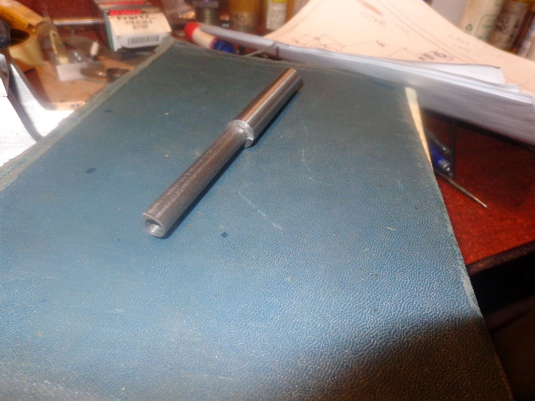
I spent the afternoon making two exhaust stack flanges. There is a bit more to these flanges than meets the eye-----They are machined thinner on one side where two of the #4 shcs go thru, to make clearance for the pushrods which pass directly over top of them. Work this size is right on the ragged edge of "Too small" as far as I'm concerned.----and---My digital camera is definitely on the way out.
 
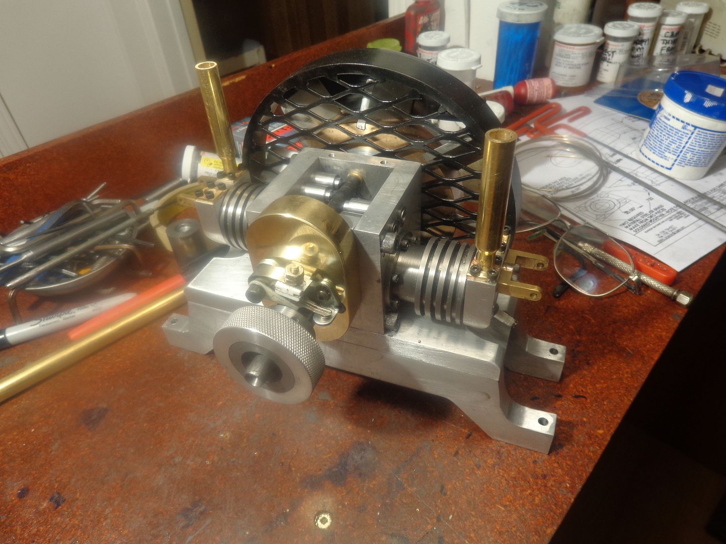
The engine now has a set of exhaust stacks. They look kind of huge, and almost overpower the rest of the engine, but I'll have to make a judgement on that after I get the induction system built and installed. I can always cut the length of them down to look better if I want to later. --On the subject of induction systems--I THINK I seen mention of someone who sells pre-bent sections of hollow brass tubing in 45 degree or 90 degree bends, but I don't remember where.--If somebody knows, please let me know.
 

Latest posts

Back
Top