Cambox and Camshaft Bearings
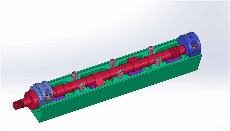
The Cambox houses the overhead camshaft, its bearings and the cam followers. Since I have completed my first camshaft, I will move on to the first Cambox.
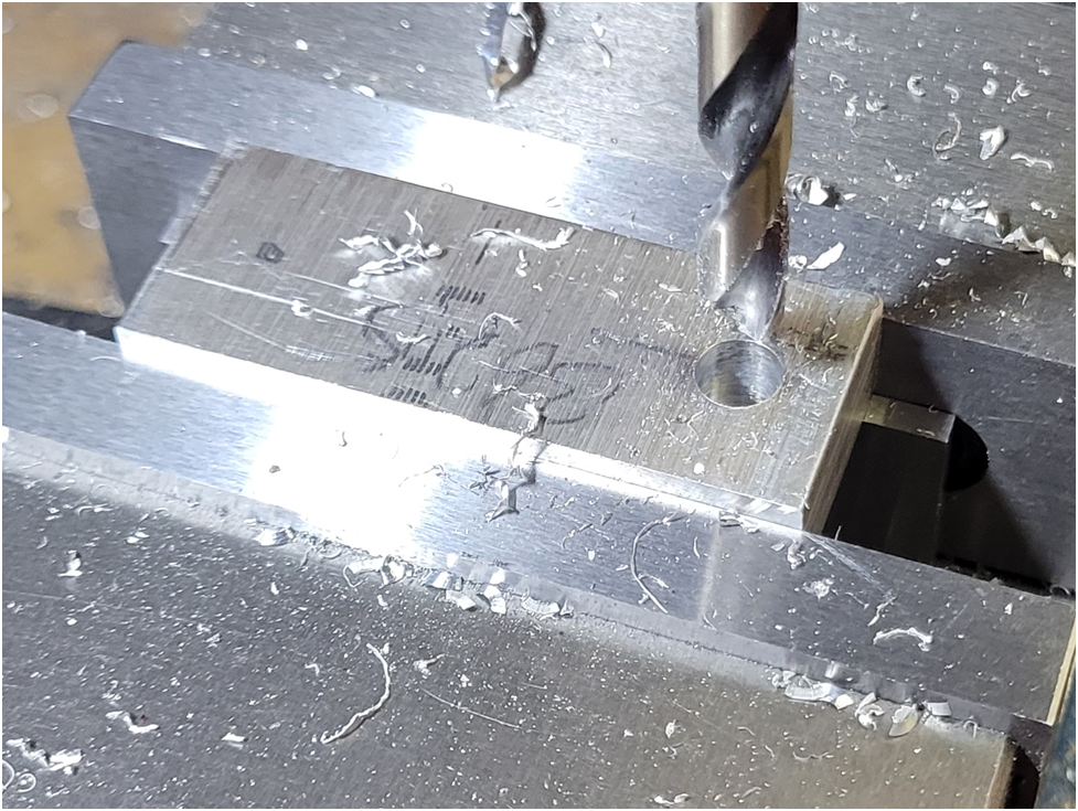
I start with an oversized work piece, fly cut the top and square off the front end. On the second cambox I will not bother fly cutting the top surface as it gets machined away. I drill the four holes for the cam followers undersized so the 1/4" end mill does not need to plunge cut. These will be milled out further so a 3/8" reamer can finish the cam follower guide holes.
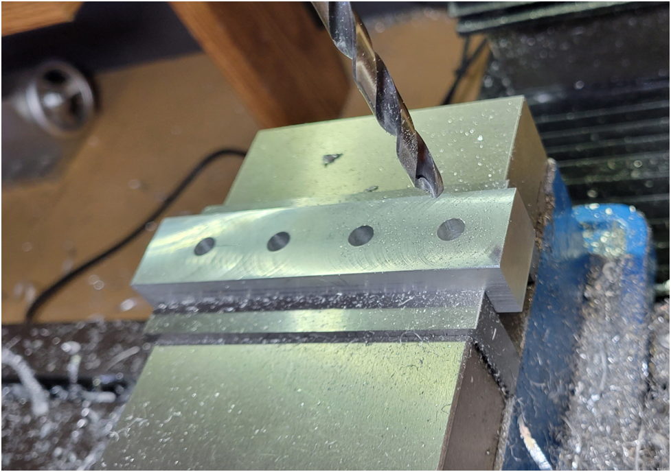
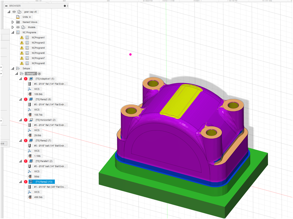
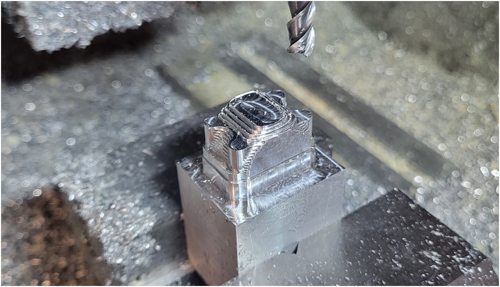
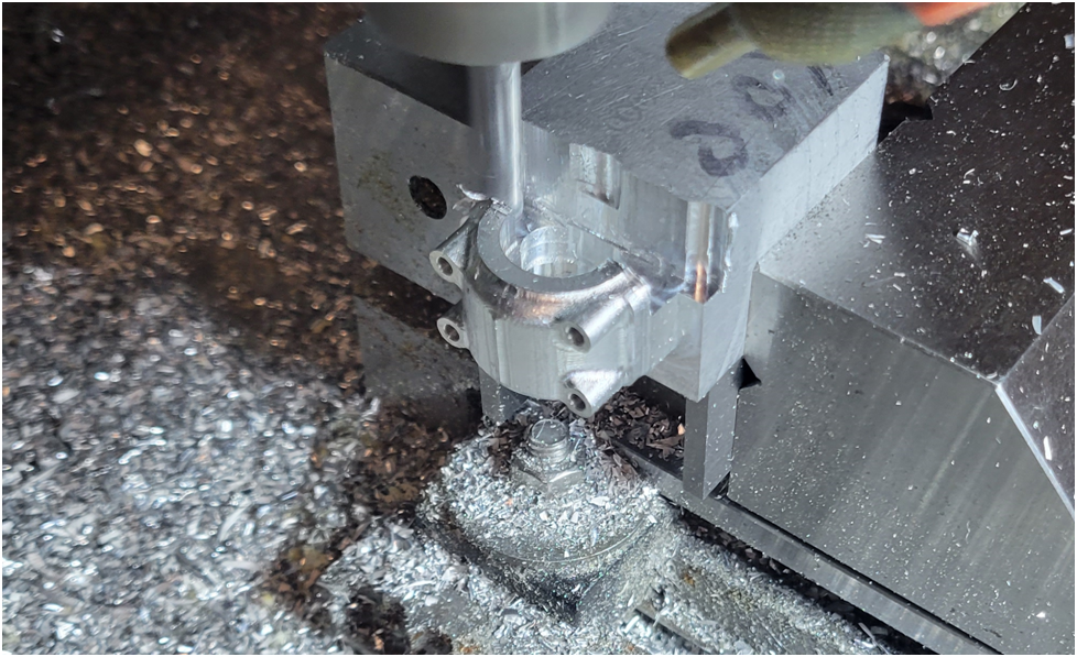
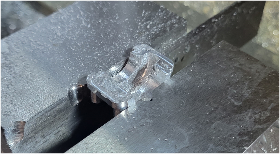
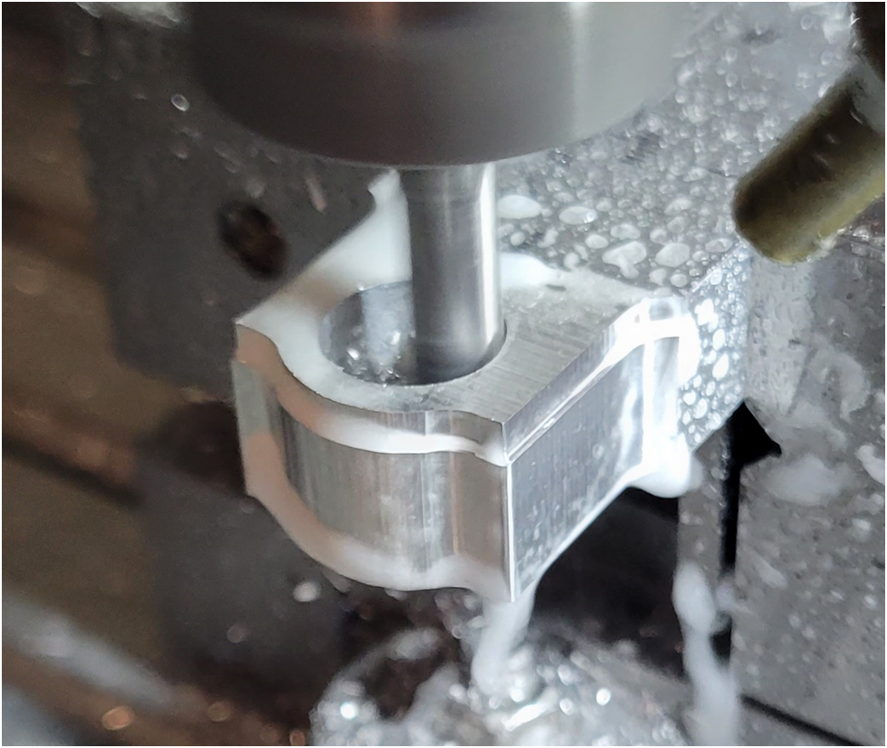
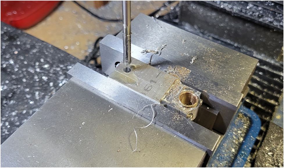
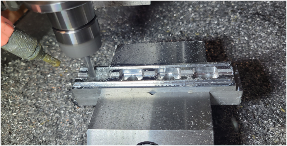
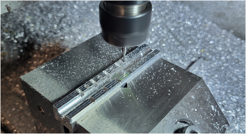
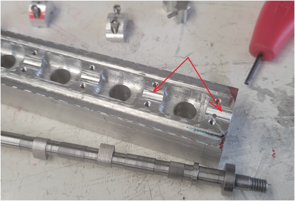
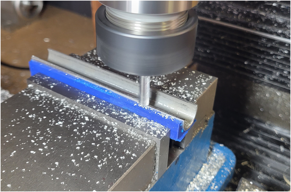
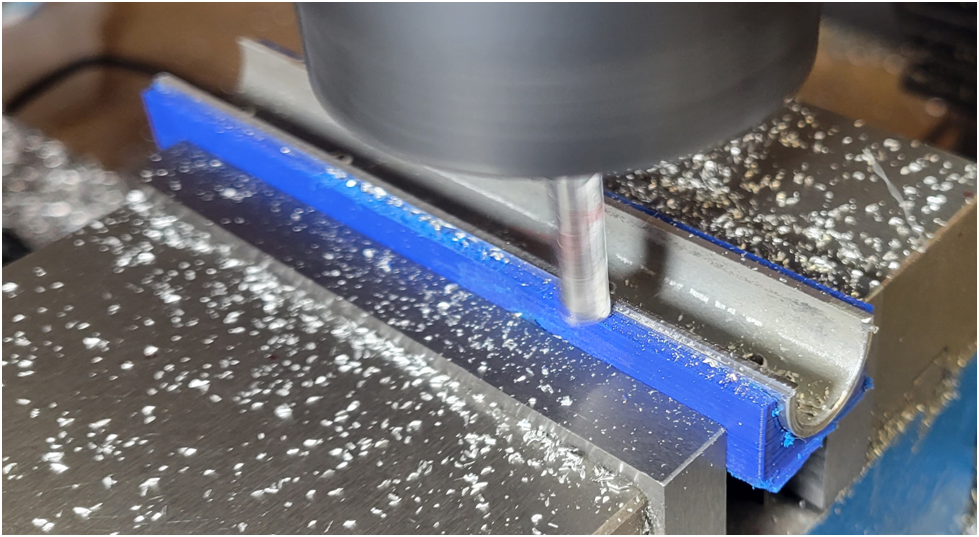
I use a 1/4" end mill to rough and finish the cam follower holes, horizontal and vertical surfaces; a 3/32 flat end mill to rough out the trough for camshaft lower bearing surfaces; a 3/16 ball end mill to "finish" the lower bearing surfaces; and finally a 1/16" flat end mill to create the holes for the camshaft bearing hold down screws. I put "finish" in quotes as the bearing surfaces will be reamed later. The bearing hold down screws will eventually pass through the cambox through clearance holes and screw into the cylinder head. But I will drill undersize and tap the holes first so I can clamp the upper cam shaft bearing clamps in place to ream the camshaft bearing surfaces.
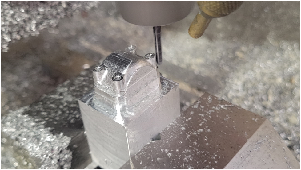
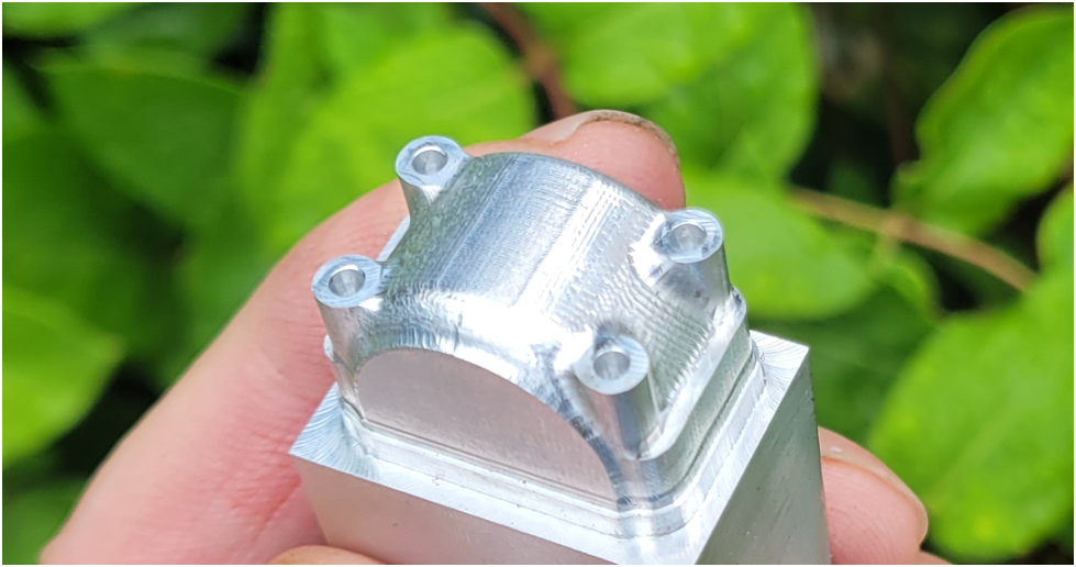
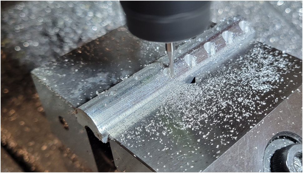
Above is the final milling operation with the ball end mill. And below the machining has been completed on the top surface of the Cambox.
The bottom surface will be machined once the gears have been depthened and then the side surfaces will be machined last as they are cosmetic.
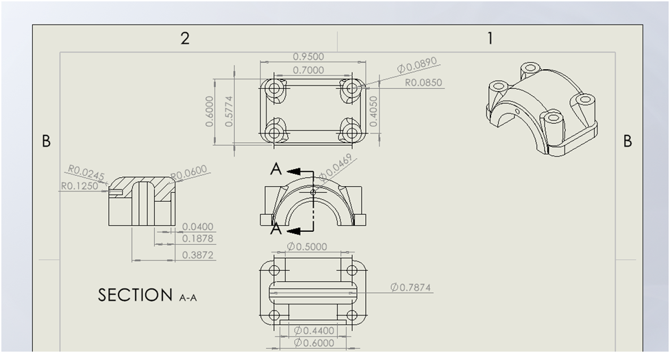
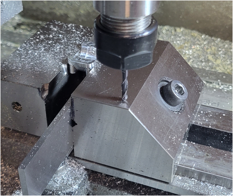
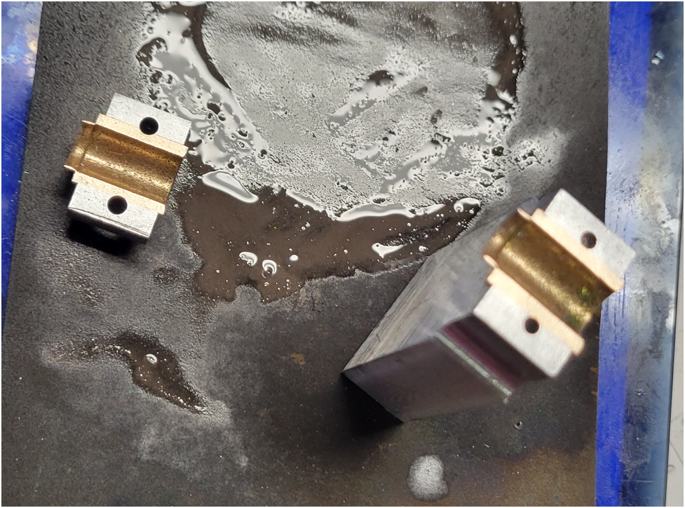
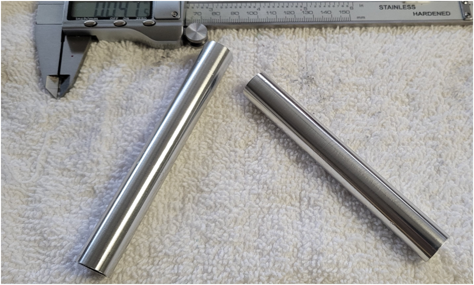
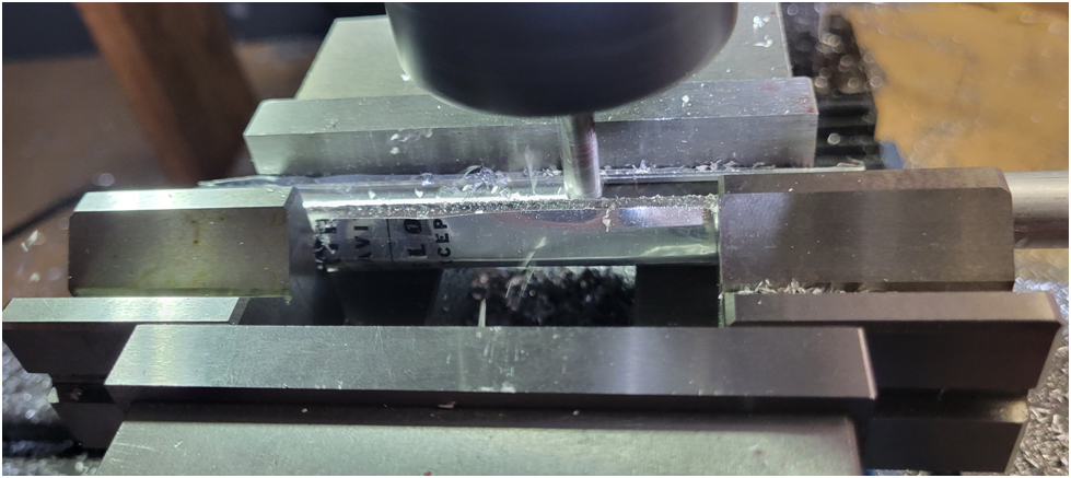
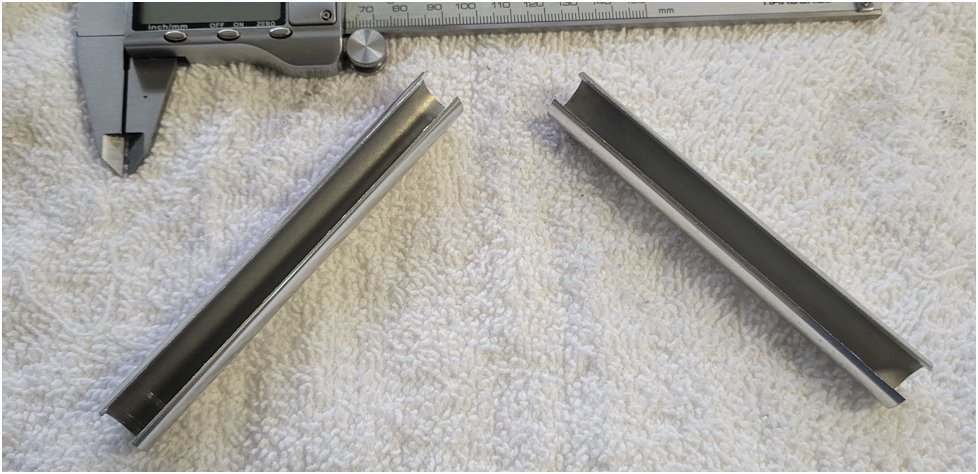
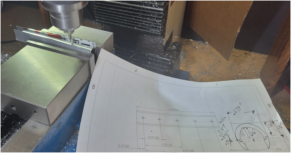
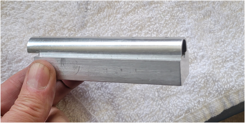
Now on to machining the camshaft top bearing caps. they will be machined as a group, then separated on the band saw, and their ends finished on the mill.
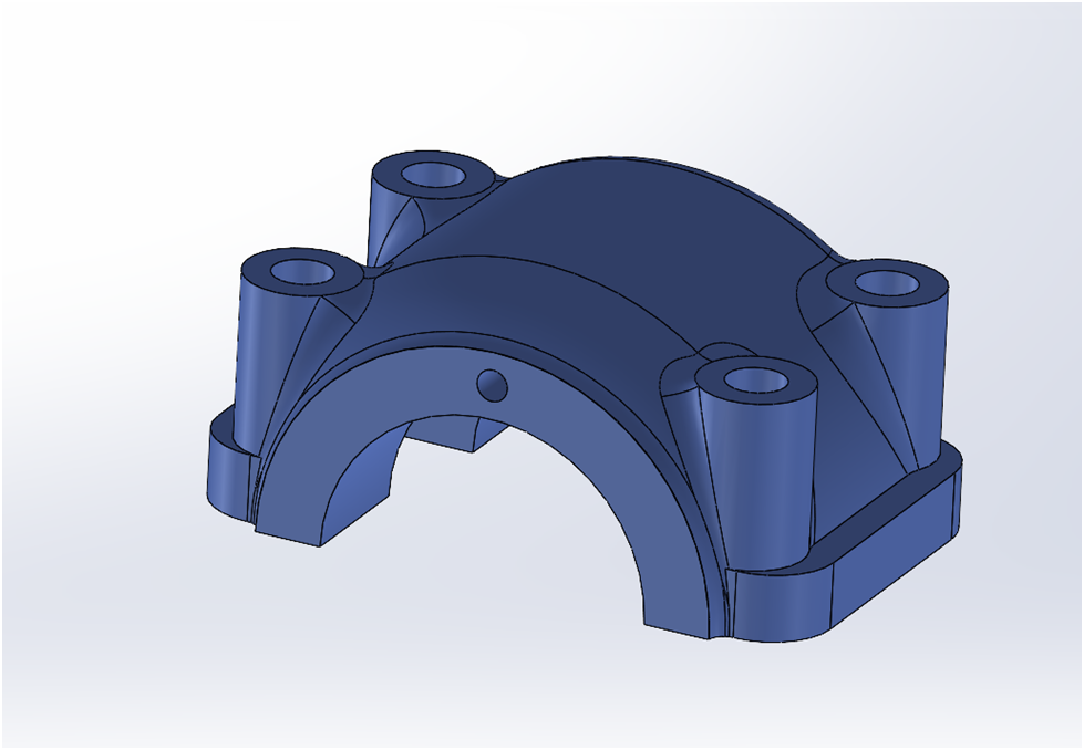
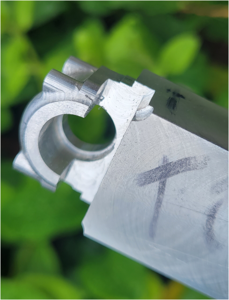
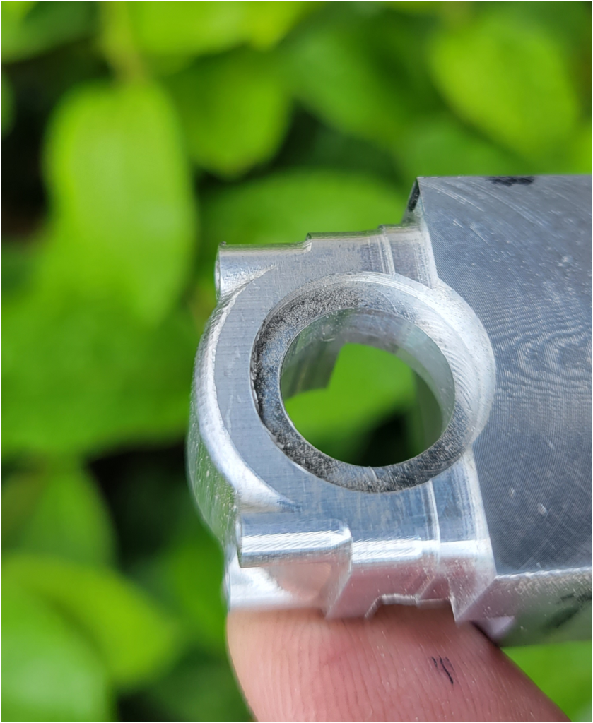
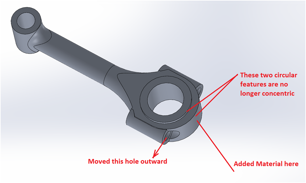
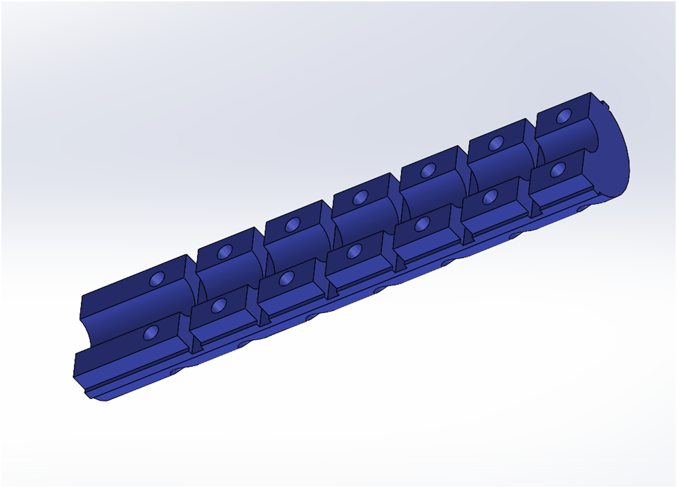
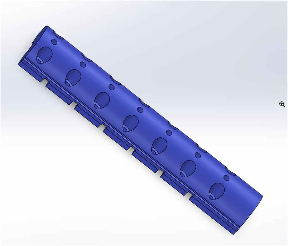
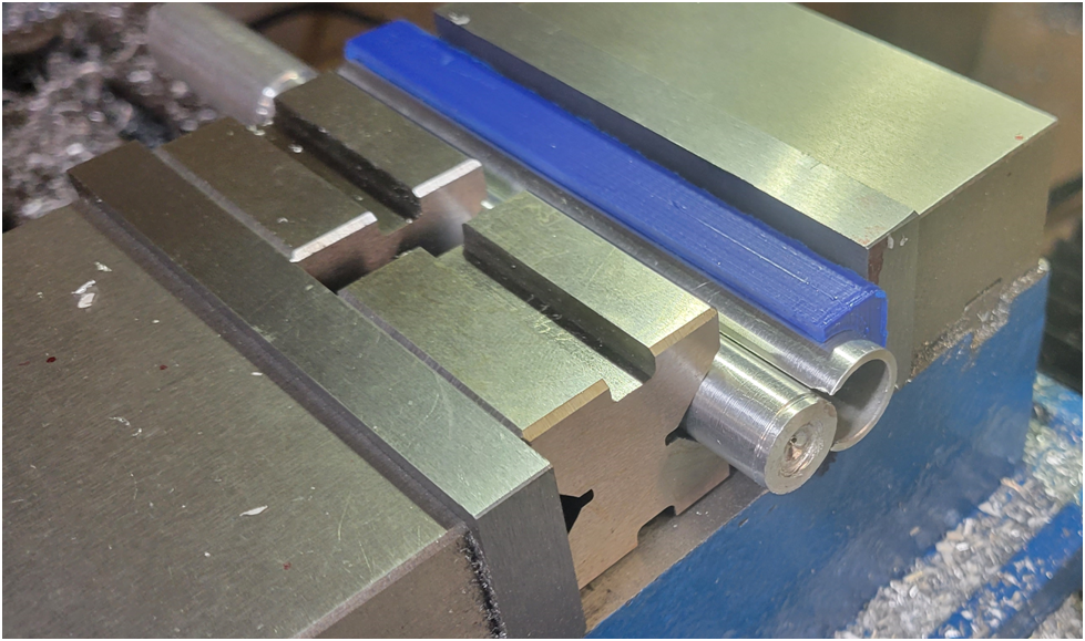
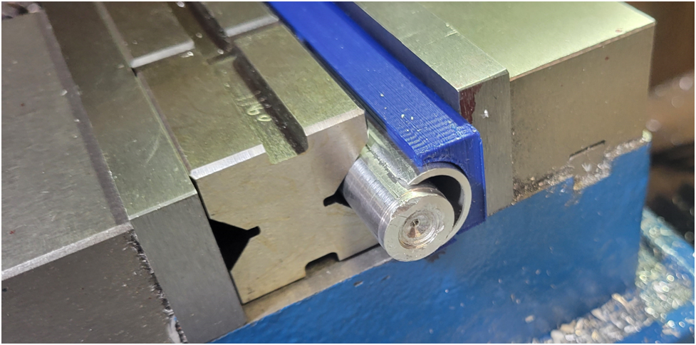
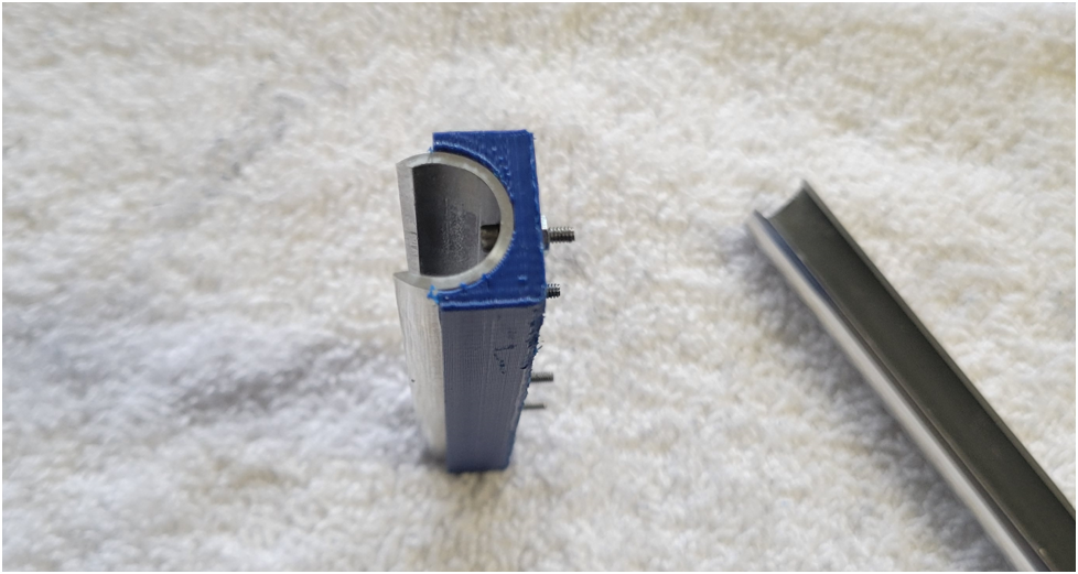
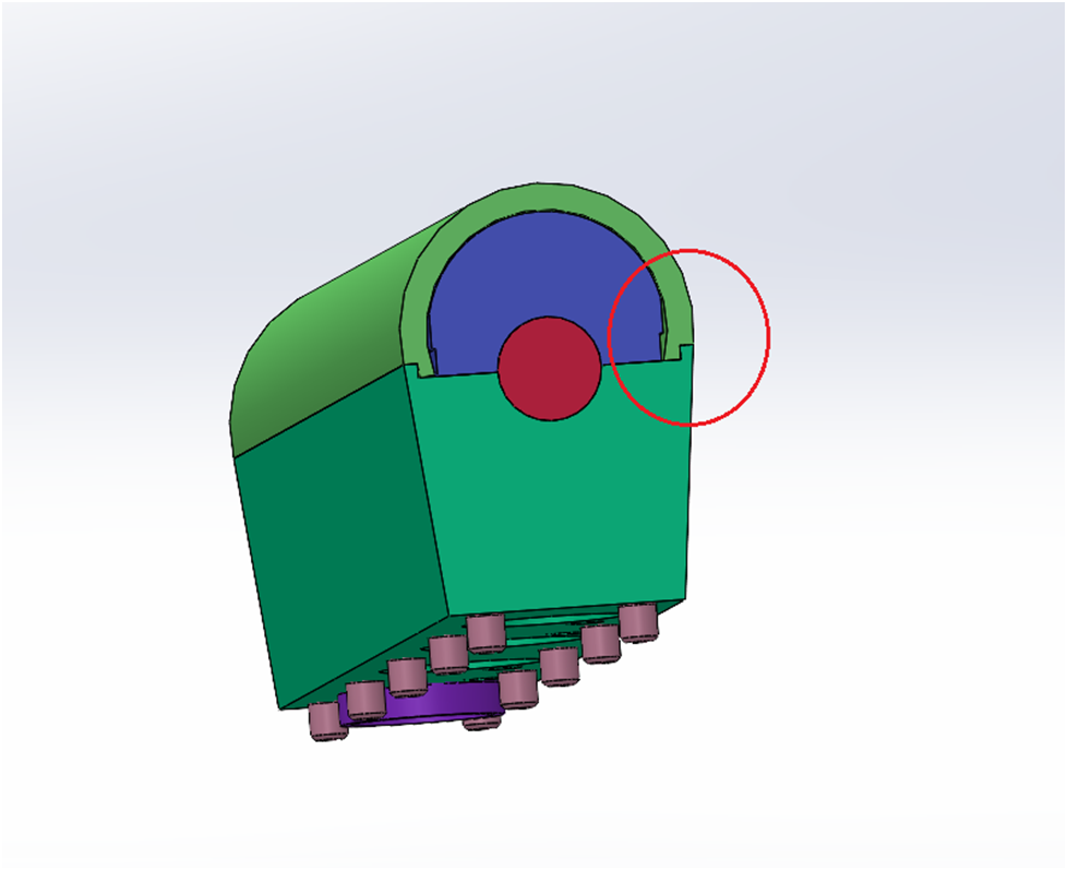
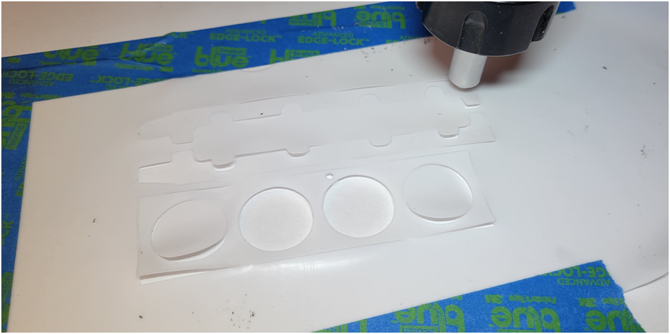
3D model of the bank of camshaft bearing clamps. The ears on the sides will be machined off later, they are vise stops and will be used instead of parallels in the vise. They provide the required space for the milling tools to clear the vise.
Below the work piece has been finished to size.
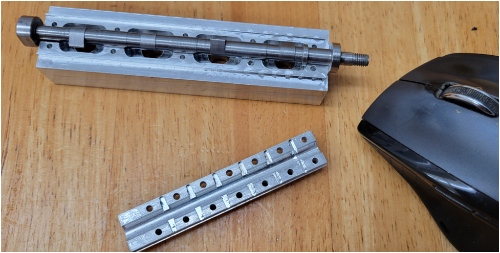
Then the bottom is machined....
The top is machined....
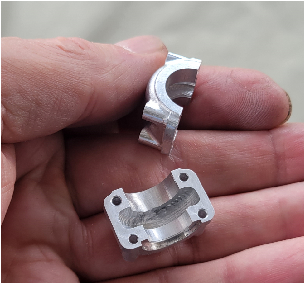
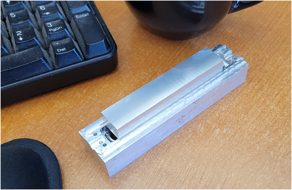
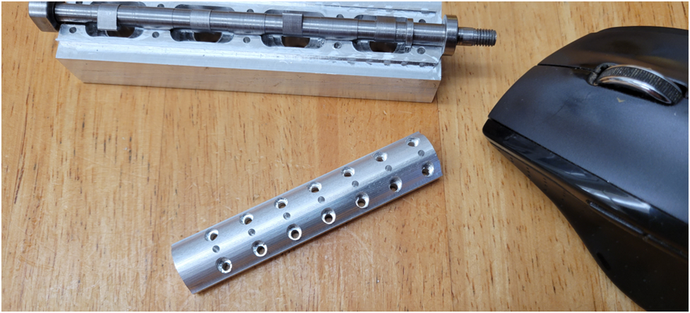
And the finished group of top camshaft bearing caps are shown below:
I am pleased with the registration of the top machining to the bottom machining. This can be seen in how well the top machined countersinks match the screw holes machined from the bottom.
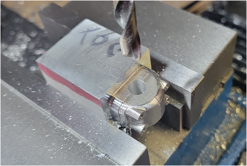
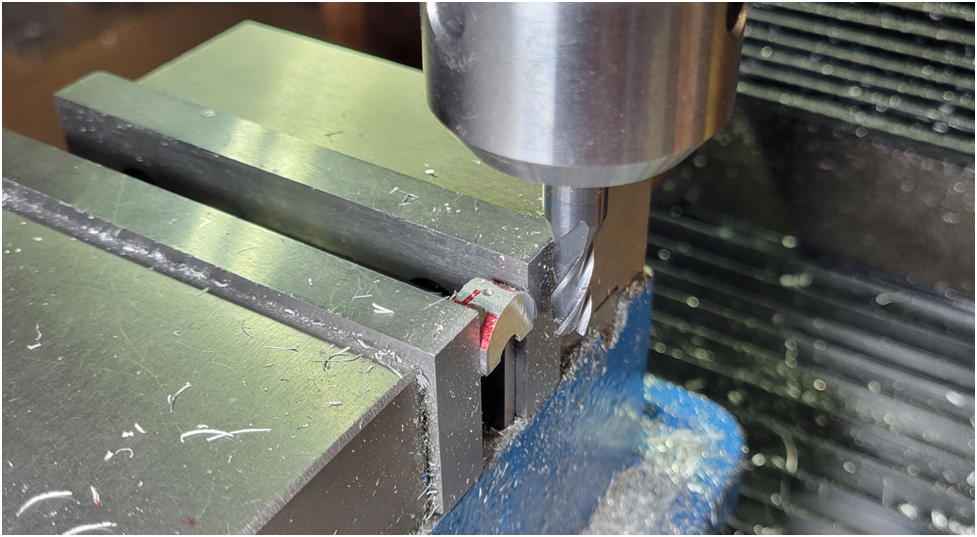
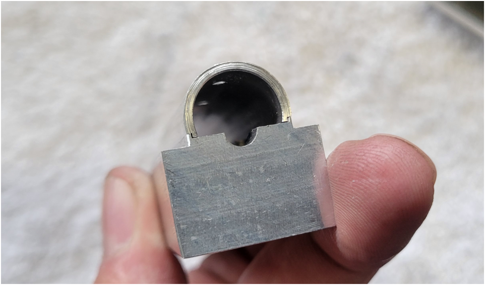
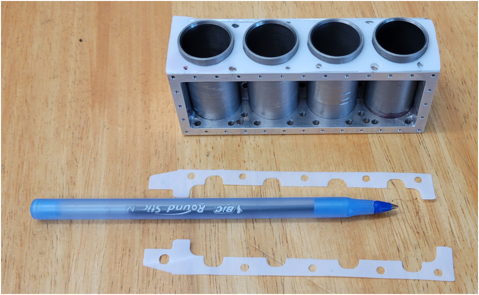
The individual caps are seperated on the band saw and then finished to final length on the mill.
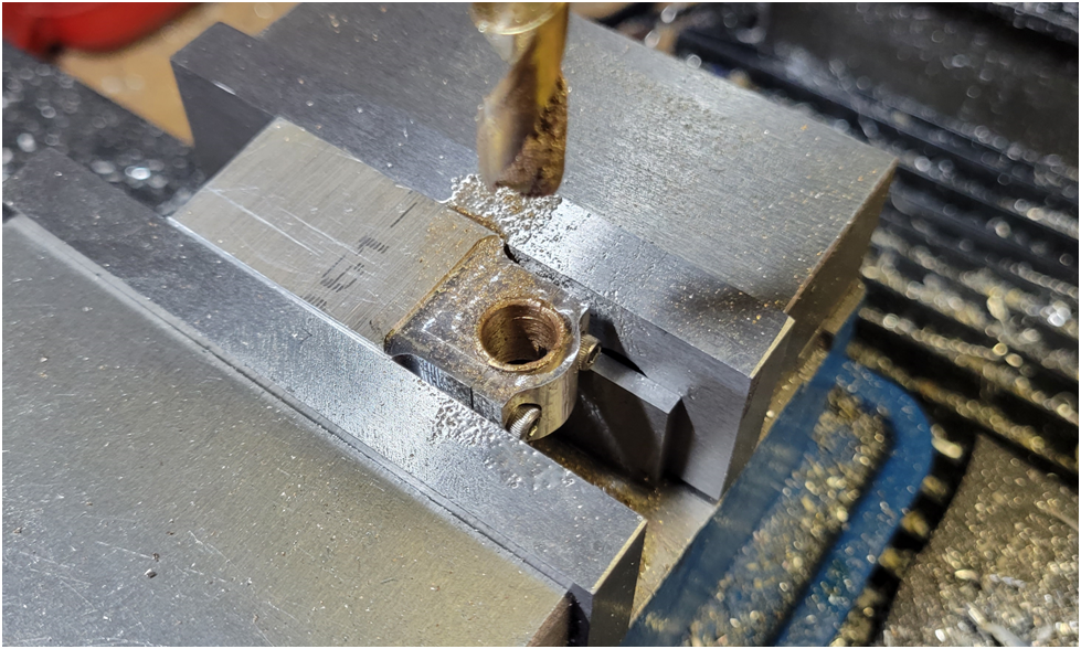
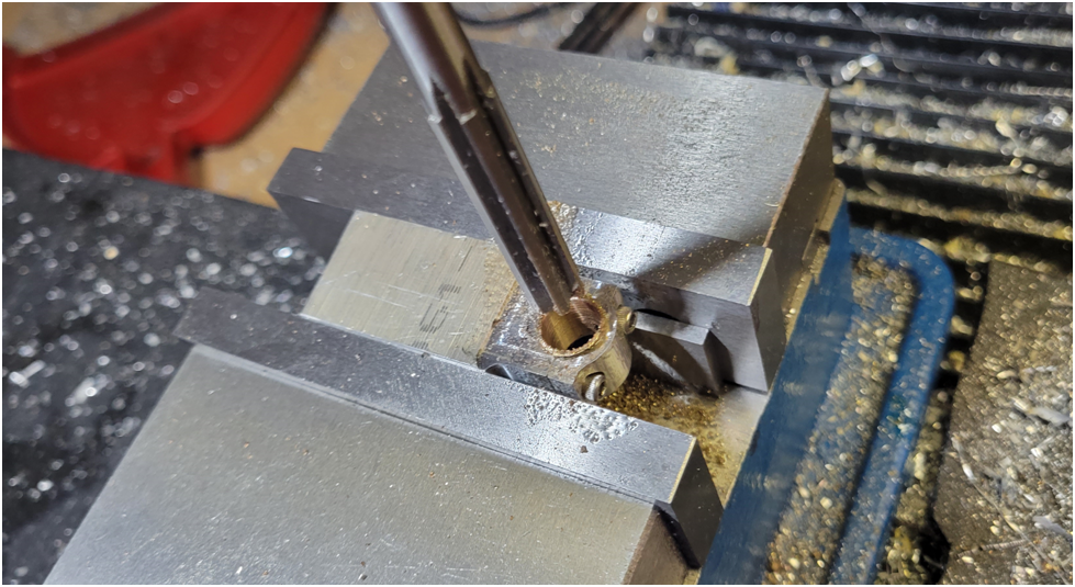
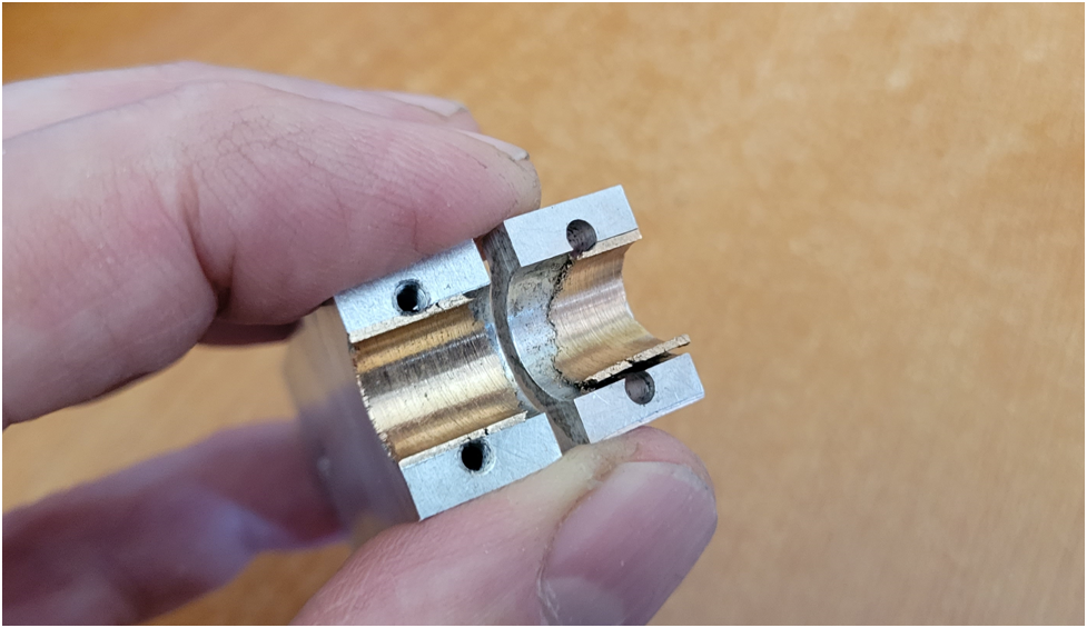
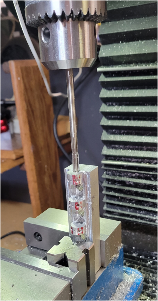
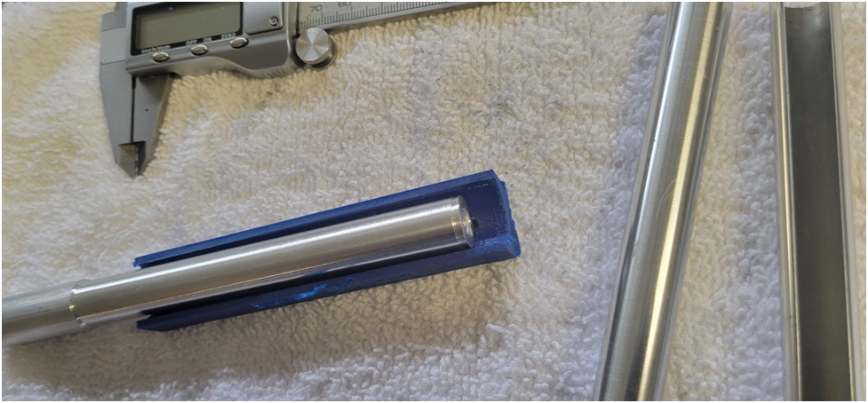
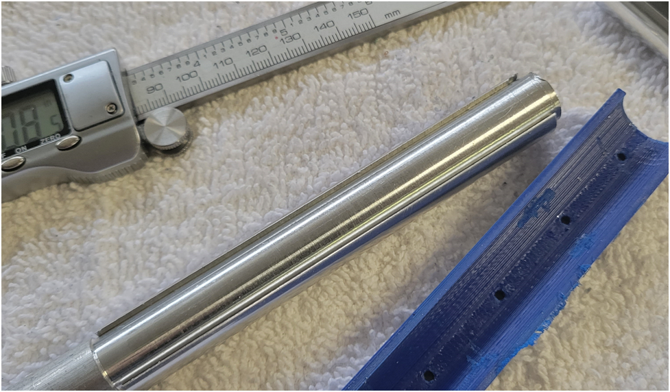
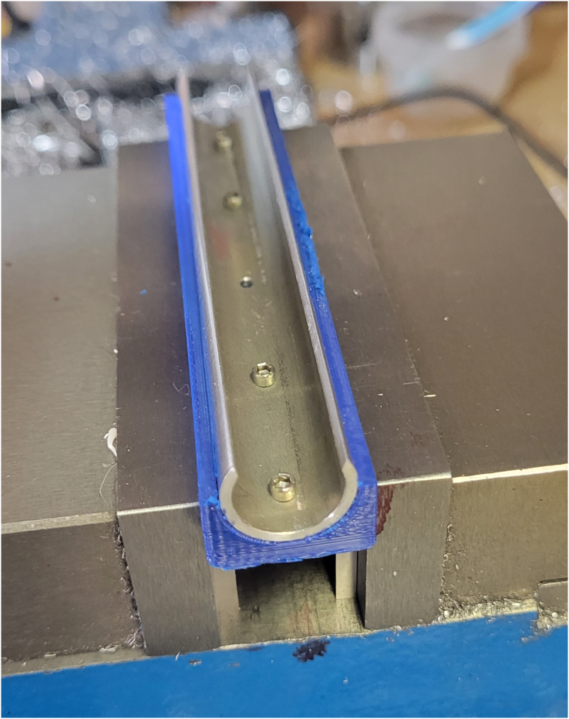
The bearing caps are clamped into place using a properly sized rod to align them, and then the camshaft bearing surfaces are reamed to size. I used a 6mm reamer because my imperial reamer set is in 1/16 increments--a .250" reamer was too big and interfered with the 2-56 hold down screws and I felt the .1875" reamer was too small for the camshaft bearing surface. So I used a .2362" reamer, known by some as a 6mm.
Then I move on to the second camshaft....
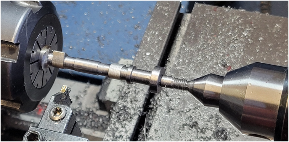
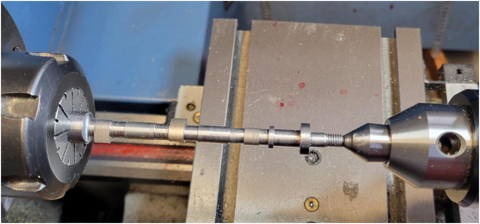
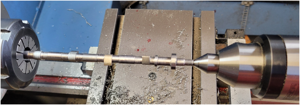
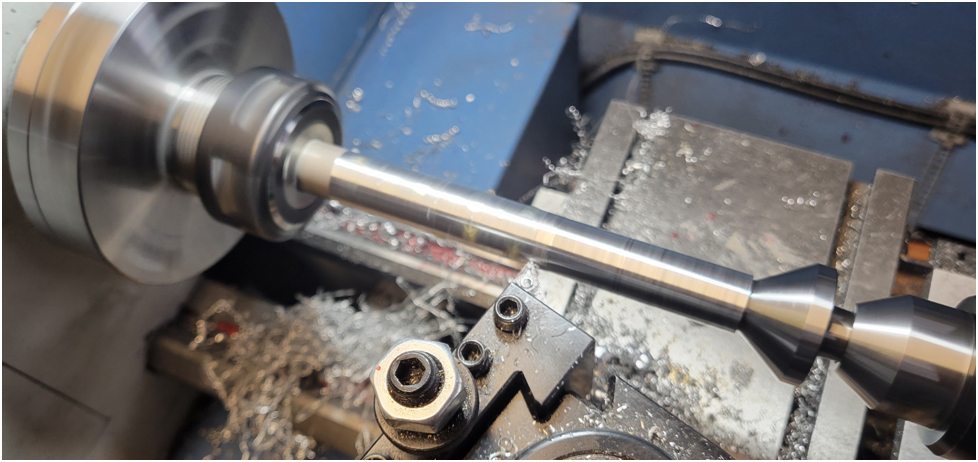
I turn on centers and machine as close to the collet as possible, extending the camshaft out section by section as shown below:
I take small cuts, advancing the cross slide .0025" at the most each cut.
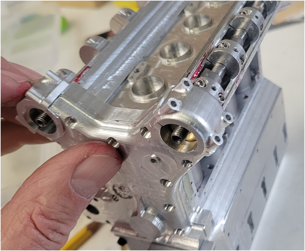
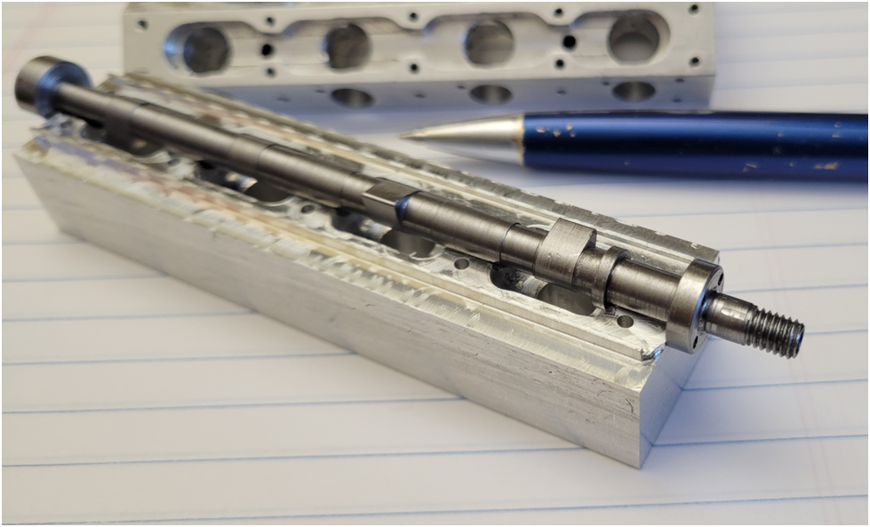
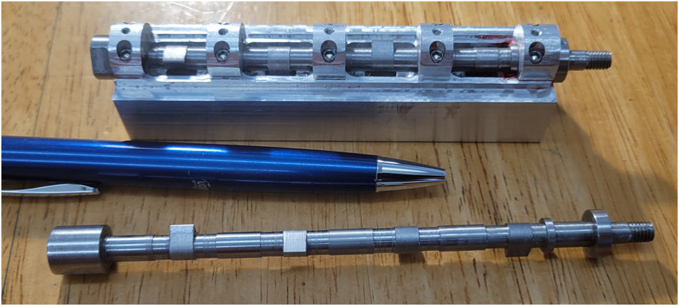
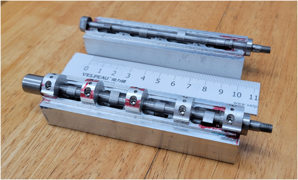
Below the first camshaft is installed in the cam box and the second camshaft is in the same state as the first.
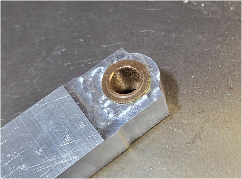
Then the second cambox, below the camshaft bearing surfaces are indicated after reaming.
Second Cambox top machining complete.
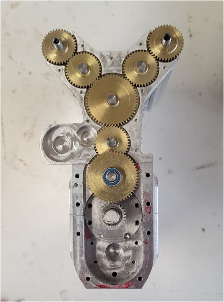
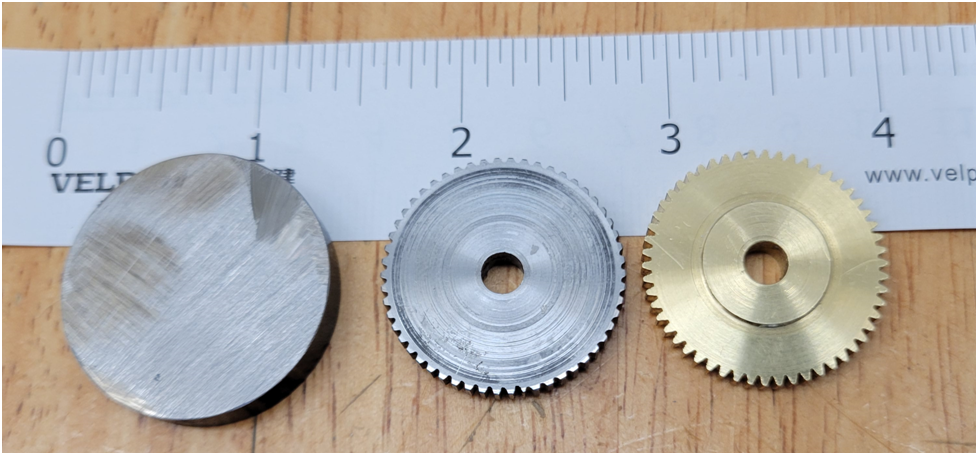
I am now going to turn my attention back to the gears. I have decided to attempt making my gears out of 1144 stressproof steel, but so far I have not had good luck. I ruined my cutter on the first attempt. I am sure I ran the cutter spindle speed too high. I took 4 cuts per tooth working up to .045" depth. If you look at the bottom of the steel gear you can see where the teeth start out OK, but as the cuts work their way around clockwise the cutter wears out.
Below is a 1144 steel gear blank on the left, a failed 1144 steel gear in the middle and a brass gear that meets print. I have bought another gear cutter and I will try slowing the spindle speed way down on the cutter, take small bites and lots of oil. We will see.....






![MeshMagic 3D Free 3D Modeling Software [Download]](https://m.media-amazon.com/images/I/B1U+p8ewjGS._SL500_.png)


![DreamPlan Home Design and Landscaping Software Free for Windows [PC Download]](https://m.media-amazon.com/images/I/51kvZH2dVLL._SL500_.jpg)


