Newest project--A Flyball Governor

Home Model Engine Machinist Forum

Help Support Home Model Engine Machinist Forum:

This site may earn a commission from merchant affiliate links, including eBay, Amazon, and others.
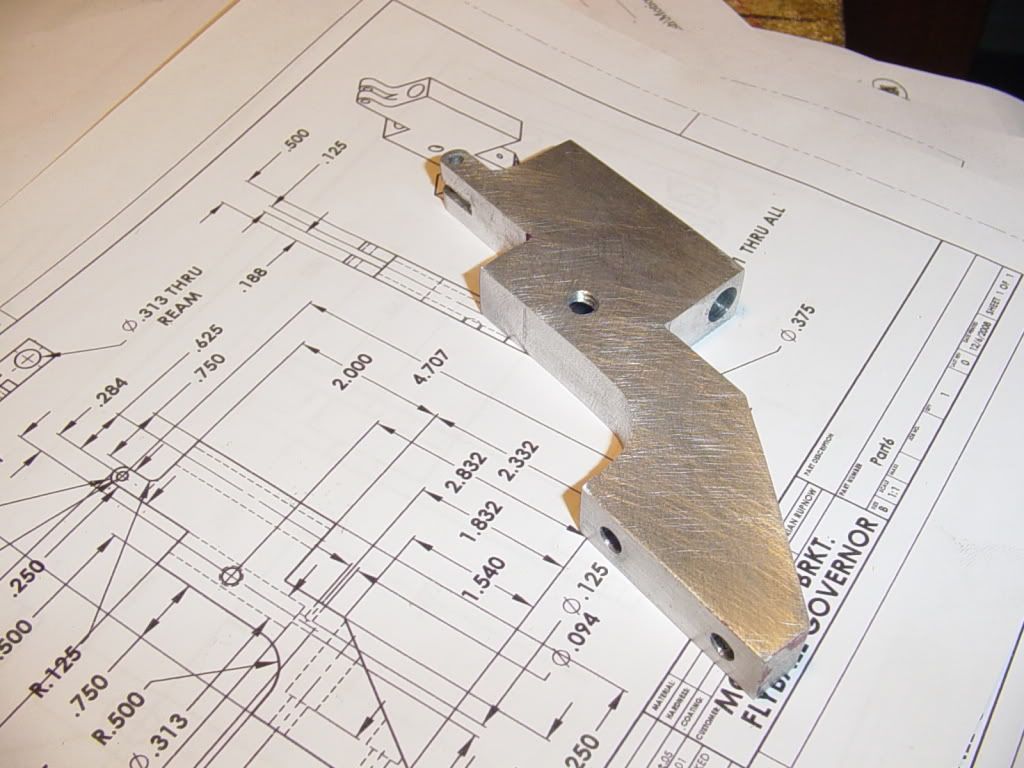
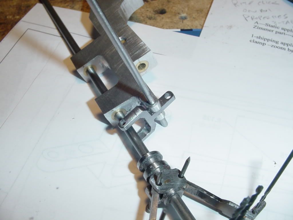
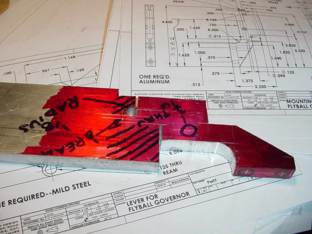
Its Saturday and I'm playing. I have started to figure out that not everything has to be milled. Much of what I do goes 10 times faster if use the bandsaw and a good file for surfaces that are not critical mating surfaces.---Case in point---The main support body for the governor. There is only one "critical" mating surface on the entire part. The rest of the surfaces are "open" and need to be cosmetically finished only.
GOVERNORSUPPORTINPROCESS001.jpg
 
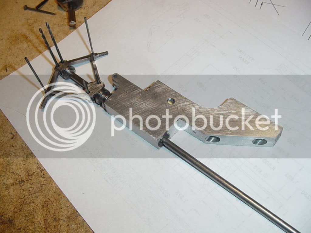
Blo*dy H*ll Brian ............ have you bought a job lot of 3/32" drill bits ;D

But on a more serious note ::) ...... great progress ......... I have trouble keeping up with your posts, never mind the machining .... keep up the good work feller :bow:

CC
 
CrewCab said:
Blo*dy H*ll Brian ............ have you bought a job lot of 3/32" drill bits ;D

But on a more serious note ::) ...... great progress ......... I have trouble keeping up with your posts, never mind the machining .... keep up the good work feller :bow:

CC

Well Actually----I was overcome by an attack of flagrant stupidity!!! Last summer, while building something, I bought a pair of small drill bits. I have been laboring under the assumption that they ware 1/16" diameter. Last week when I phoned my tool guy to order a 3/32" reamer, I said---"Oh yeah---When you bring over the reamer, bring me a couple of the right sized drills to go with it."---(His shop is on the other side of town, but he lives near me.) And then---I went to get one of what I thought were the 1/16" drill bits, and damned if they weren't 5/64"---the same size as I had just bought.---Don't get old. die young!!! When ya get old, ya get stoopid!!! :'( :'( :'(
 
I'm new around here and have just gotten around to following this thread. Really neat project. It will really add something to the appearance of that engine.

Just wandering if anyone has given any thought to the failure modes and the consequences of failure. At the speeds and loads involved here I'm sure there is no danger, I'm just thinking. How does it go in full scale steam engines driving a load, what happens?

1. If the upper pivot pin fails the spring drives the collar to the bottom and the valve is wide open - overspeed.

2 If the middle pivot pin fails, same as above.

3. If the lower pivot pin fails, same as above.

4. If the collar escapes the control fork, I'm not sure which way the valve would go.

5. If the drive belt parts or jumps the groove, rotation halts, the balls fall and the throttle goes wide open.

Other failure modes, say the loss of a weight or bushing failure or failure of any part of the linkage the the consequences would vary. What happens? I have no real world experience but it seems like it would be a good idea to design some linkage with a "fail safe" limit that would close the valve and become locked out until reset if the engine exceeds a safe speed. I'm thinking of this as some kind of mechanical intelligence that is getting its signals crossed. It is seeing a need to open the throttle when it should be doing the exact opposite.

Is this a problem in the real world of steam power?

Jerry
 
According to the old timers around this way, broken drive belts were a common failure - it meant a quick jump to the shut-off valve.
 
CJ,

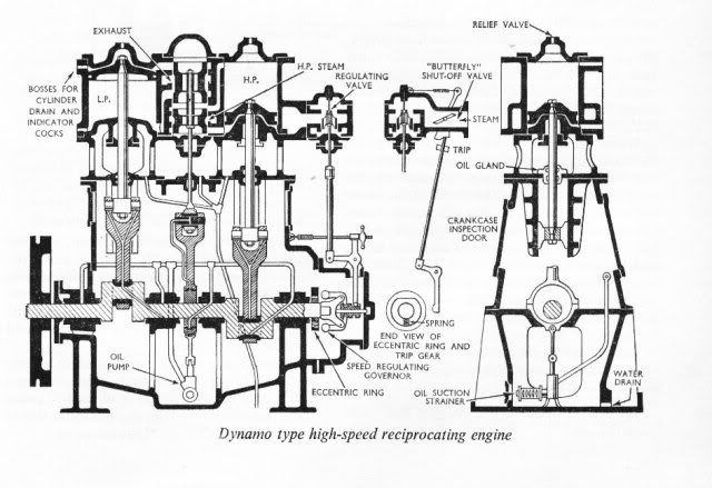
Here's what we had in my day or variations on the theme.
059.gif
.

Should the eccentric fail to fly out and trip the machine, things could get quite exciting and more than one engineer/stoker has been chased round the engine room by lumps of generator or found in a quivering heap under the condenser surrounded by the remains.
icon2.gif
nervous777.gif
666.gif


The was one particular boiler feed pump which had a nasty habit of overspeeding and shedding its turbine blades through the casing - Admiralty solution a bloody great strap 1.25" solid semicircle over the casing, when they failed the blades only got as far as the strap, mind you the steam sure gave you a run for your money
wow.gif
wow.gif


OST.jpg


Best Regards
Bob
 
joeby said:
I'm not sure if this is relevant to the discussion; but this http://www.rustyiron.com/literature/Flywheel_Explosions.pdf is an interesting look at what happens when a full size steam engine overspeeds.

Kevin
That's a fascinating article, especially the parts on flywheel design and how the max speed of a flywheel is entirely determined by the material it's made of, not thickness or anything else.Well-made wooden flywheels can run safely faster than cast iron ones.

Also there's this bit-- I never knew before why flywheels had 'S' spokes--


sicurve.GIF
 
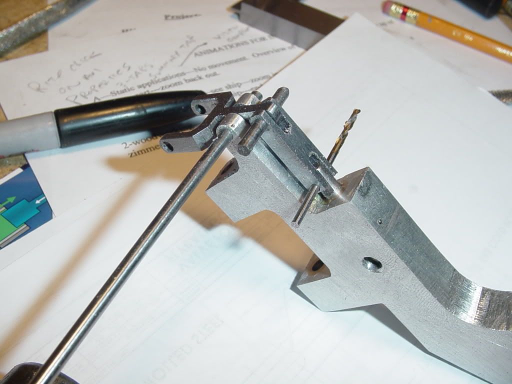
This morning, I built the lever. I am just about finished the fiddly little bits, thank God!!! You will see that I have cut away part of the main body that I made yesterday. I started out to do this because it looked too "heavy" through that area. Then as I proceeded with it, I realized that it will serve a real purpose rather than a purely cosmetic one. I need to put a shaft collar in that cut out area to keep the entire shaft and governor from dropping down when it is in a balls up attitude. The hub on the o-ring pulley will keep the shaft from trying to move up, but I had notheing in the design to keep the shaft from dropping down. so---form does not always follow function. This time it was reversed!!! Now---off to build the link and a valve.
LEVER001.jpg
 
Well Sir!! Now if I can just get the .094" drill rod thats on order, and Chucks brass balls (Well, not his, the ones he put in the mail for me,) then I'm almost in business for a test run in the variable speed electric drill. Actually the lever, link, and valve seem to work very well together, with no binding, but I won't really be able to tell untill I get some drill rod shafts into those pivot points that are now occupied by all my drill bits.
valveinstalled001.jpg
 
Lookin' real good Brian - you have been hard at it.

Now here's a little tip re all those pins - I bash the flux off a suitable sized welding electrode, polish 'er up with a bit of fine emery, and make my holes to suit that.
 
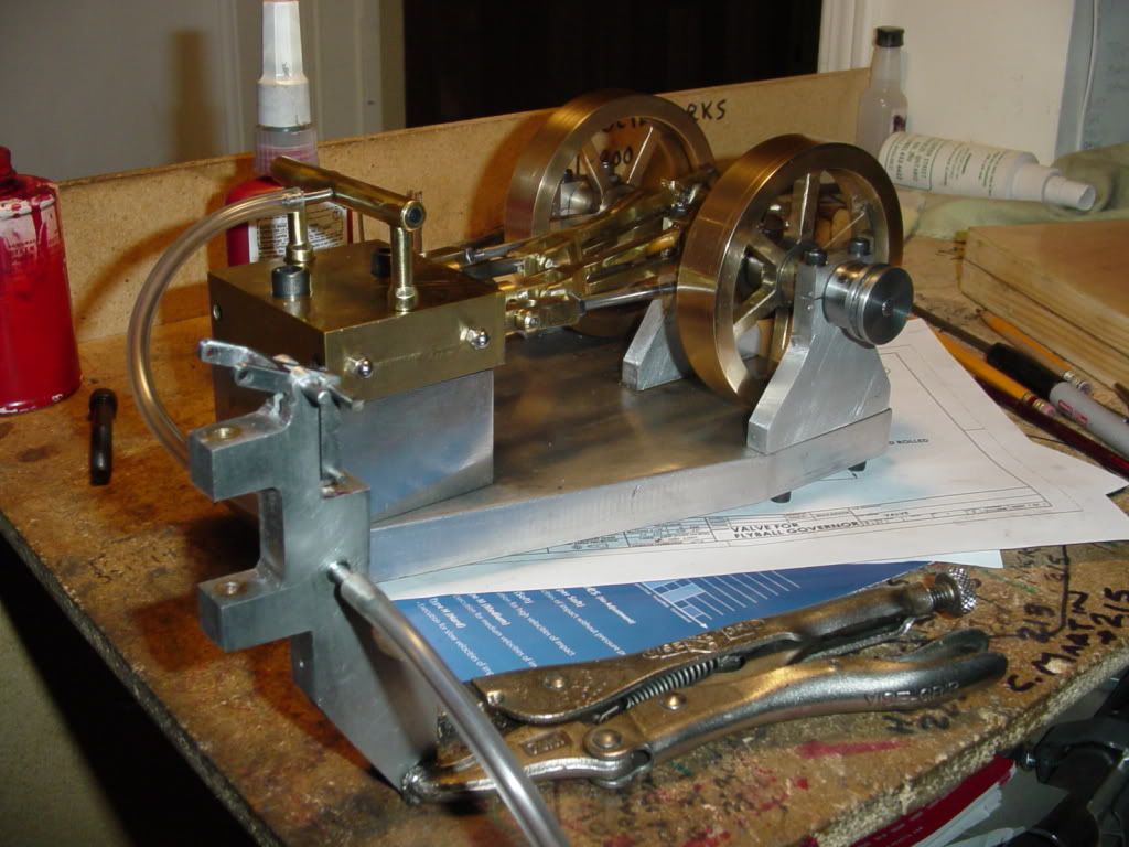
Very happy to anounce that the first test is a big success!!! I finished everything to do with the lever, link, valve, and body. I ran my airline thru the valve body and started the engine under a much higher pressure than I normally would. The engine just about took off and flew around the room, but when I operated the lever it shuts the engine right down to a very slow idle--and this is in a "no load" situation. If the engine was driving something and had that extra resistance to overcome, it would stop completely.This engine runs great on about 8 PSI of air. When I have 40 PSI on the regulator there is enough air escaping around the valve to keep the engine running at a very slow idle. When I move the link into what would be a "balls in" configuration of the governor, it takes off like the devil was after it. It takes very little pressure to move the lever, and I'm glad that I put the air bleed hole in the bottom of the valve chamber, because there is enough air escaping around the valve that it will actually shift the lever if I plug that bleed hole with my finger!!! The valve travels about 1/4" from full open to full close, and the effect on the engine is that it speeds up or slows down in a very "controlled" manner. There is a 2:1 ratio built into the lever, so that the bottom collar of the governor has to move 1/2" from "balls in" to "balls out" to move the valve thru its 1/4" of travel. This is all very encouraging, and makes me think that the governor is actually going to work as I intended.
firsttest001.jpg
 
Captain Jerry said:
I'm new around here and have just gotten around to following this thread. Really neat project. It will really add something to the appearance of that engine.

Just wandering if anyone has given any thought to the failure modes and the consequences of failure. At the speeds and loads involved here I'm sure there is no danger, I'm just thinking. How does it go in full scale steam engines driving a load, what happens?

1. If the upper pivot pin fails the spring drives the collar to the bottom and the valve is wide open - overspeed.

2 If the middle pivot pin fails, same as above.

3. If the lower pivot pin fails, same as above.

4. If the collar escapes the control fork, I'm not sure which way the valve would go.

5. If the drive belt parts or jumps the groove, rotation halts, the balls fall and the throttle goes wide open.

Other failure modes, say the loss of a weight or bushing failure or failure of any part of the linkage the the consequences would vary. What happens? I have no real world experience but it seems like it would be a good idea to design some linkage with a "fail safe" limit that would close the valve and become locked out until reset if the engine exceeds a safe speed. I'm thinking of this as some kind of mechanical intelligence that is getting its signals crossed. It is seeing a need to open the throttle when it should be doing the exact opposite.

Is this a problem in the real world of steam power?

Jerry
Somewhere, don't know where, I saw a setup on a mill engine that had an idler pulley that ran on top of the gov. belt. Pulley was mounted on an arm connected to the throttle valve, so if the belt broke the arm dropped down & shut the engine down...overspeed situations are nasty & scary on any kind of engine...
 
Engines generally have an overspeed trip that is separate and works independently of the governor that will shut off the steam/fuel/air etc... to the prime mover in the event of an overspeed.

Jim
 
Sounds great Brian. :bow: :bow:

Now we just have to wait till it gets cold enough to freeze the b@!!$ off the brass monkey and you can finish this portion of this project up. It definitely looking good Brian. Keep up the good work.

Cheers :)

Don
 
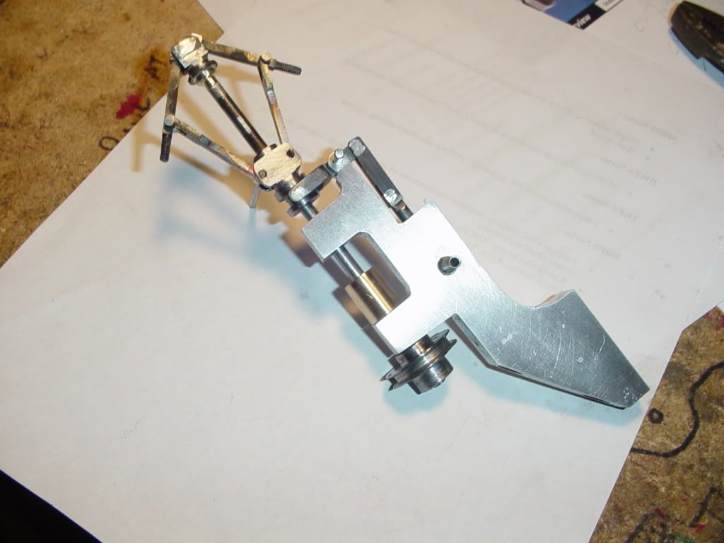
Now if I just had Chucks brass balls-----Damn--Its been a week now since he sent them, and Toronto is less than 100kM away.-Hope some postal worker didn't think they were gold and rip me off---
NEARLYDONE002.jpg
 

Latest posts

Back
Top