Maryak---The pin chuck I had was cheap Chinese crap. It was a 3 jaw but extrememly poor quality. I just went down to Canadian Tire and bought a replacement 3 jaw chuck for a 3/8" drill. This chuck has a 3/8"-24 fine thread in the back of it. I screwed a 3/8" bolt with the head cut off into the back of the chuck, chucked up a peice of 3/8" cold rolled round stock in the jaws, then mounted the 3/8" cold rolled in my lathe and turned down the shank of the 3/8" bolt to 11/32" diameter. It works perfect now, as a pin chuck when mounted in the big chuck on either my lathe or my mill. It will hold drills down to 0.040" dia. anything smaller than that, I don't want to work with anyways.---Brian
You are using an out of date browser. It may not display this or other websites correctly.
You should upgrade or use an alternative browser.
You should upgrade or use an alternative browser.
Newest project--A Flyball Governor
- Thread starter Brian Rupnow
- Start date

Help Support Home Model Engine Machinist Forum:
This site may earn a commission from merchant affiliate
links, including eBay, Amazon, and others.
Yep, yep, yep!!! Just like pickin' fly poop outa pepper!!!

K
Kludge
Guest
Brian Rupnow said:According to what I have read on the subject, the spring helps in a large way to dampen out the oscillations.
It will still oscillate. Think about a car with bad shocks - same idea. If you put that dampening disk I mentioned on another thread somewhere on your part #5, so it's riding against the center shaft, it should do the trick.
Best regards,
Kludge ... who's gonna hide before he gets into more trouble. ;D
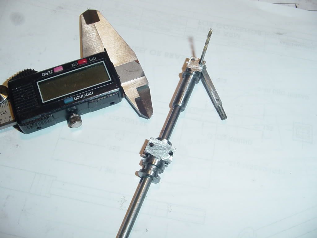
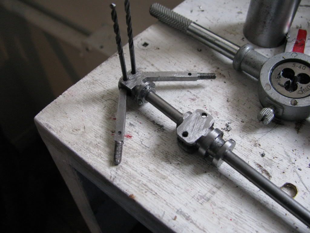
I finished machining the second upper arm this morning. I am still messing around with this new camera, trying to figure out the best way to position and light still shots. It works really good for videos, but doesn't want to focus very well under low light conditions. This shot was taken over by the window in my little machine shop.

mklotz
Well-Known Member
Brian,
Your new camera will probably have a means of setting the ISO number. In the old days, film was rated with ASA numbers and the higher the number, the more sensitive the film, i.e, the better able it was to capture images in low light. ISO numbers are numerically equivalent to ASA numbers (just a different standards organization).
It's not clear to me how the sensitivity increase is accomplished in a digital camera (photo experts feel free to chime in here) but, increasing the ISO value your camera is using will allow you to take pictures in low light conditions without flash. Higher ISO values will also increase noise sensitivity but Canon does a good job of managing this in their cameras.
Check your camera manual. If it's like most of the Canons with which I'm familiar, you'll need to use the 'P' setting on the mode dial and then the 'FUNC SET' menu to change the ISO setting.

$104.99
Sunnytech Hot Air Stirling Engine Motor Steam Heat Education Model Toy Kit M16-CF
stirlingtechonline

$99.99
AHS Outdoor Wood Boiler Yearly Maintenance Kit with Water Treatment - ProTech 300 & Test Kit
Alternative Heating & Supplies
![DreamPlan Home Design and Landscaping Software Free for Windows [PC Download]](https://m.media-amazon.com/images/I/51kvZH2dVLL._SL500_.jpg)
$0.00
DreamPlan Home Design and Landscaping Software Free for Windows [PC Download]
Amazon.com Services LLC

$599.00
$649.00
FoxAlien Masuter Pro CNC Router Machine, Upgraded 3-Axis Engraving All-Metal Milling Machine for Wood Acrylic MDF Nylon Carving Cutting
FoxAlien Official

$39.14
$49.99
Becker CAD 12 3D - professional CAD software for 2D + 3D design and modelling - for 3 PCs - 100% compatible with AutoCAD
momox Shop

$171.00
$190.00
Genmitsu CNC 3018-PRO Router Kit GRBL Control 3 Axis Plastic Acrylic PCB PVC Wood Carving Milling Engraving Machine, XYZ Working Area 300x180x45mm
SainSmart Official

$19.15
$29.95
Competition Engine Building: Advanced Engine Design and Assembly Techniques (Pro Series)
MBC Inc.

$26.89
$34.99
Peachtree Woodworking Supply Bowl Sander Tool Kit w/Dual Bearing Head & Hardwood Handle, 42 Pieces Wood Sander Set, 2 Hook & Loop Sanding Disc Sandpaper Assortment, 1/4 Mandrel Bowl Sander
Peachtree Woodworking Supply Inc
Also try using a darker background then the camera won't darken everything to compensate for the bright background, I use a mid blue background but grey or green work just as well.
Jason
Jason
If you're not already, kick it into Macro mode (universally symbolized by a Tulip for some reason) and then keep an eye on the display where it tells you what the focus distance is for whatever zoom you're at and try to stay inside that.
spuddevans
Well-Known Member
- Joined
- Feb 25, 2008
- Messages
- 203
- Reaction score
- 1
mklotz said:It's not clear to me how the sensitivity increase is accomplished in a digital camera (photo experts feel free to chime in here) but, increasing the ISO value your camera is using will allow you to take pictures in low light conditions without flash. Higher ISO values will also increase noise sensitivity but Canon does a good job of managing this in their cameras.
I'm no expert, just an avid enthusiast. I stand (or sit) to be corrected, but I think this is how it works.
The little device, either a CCD (Charge Coupled Device) or CMOS (Complimentary Metal Oxide Silicon) chip is what converts the light into a digital output onto your memory card.
The CCD or CMOS has literally millions of photo-detectors (pixels)or sites that will convert light into a voltage, the brighter the light the greater the voltage. ( when I say greater voltage, I'm talking about milivolts)
When you select the lowest or standard ISO (sensitivity) you are using the minimum amplification from the CCD or CMOS chip and thus giving you the best picture quality that your camera can give.
However, if you are wanting to take pictures in darker conditions you can on most camera's increase the ISO (sensitivity) and that then amplifies the output of the CCD or CMOS sensor to produce the same output as when you have normal light conditions.
So why not use higher sensitivities all the time and be able to take pictures in the dark? Unfortunately when you use the higher sensitivities ( ISO's ) you also amplify digital noise that is present in the CCD or CMOS chip. Normally the noise is so low as to not be noticed, but when amplified using higher ISO's it becomes visable especially in shadowy or dark areas of the picture.
I hope this is understandable.
Tim
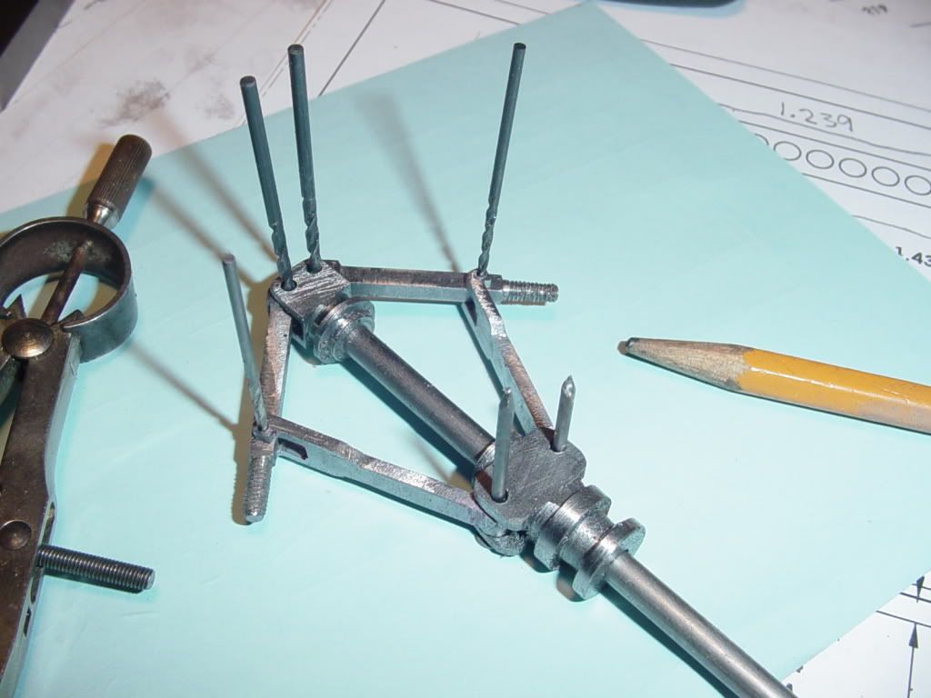
Thanks for all the camera tips guys. I will definately try them all. In the meantime, here is a picture taken with my old Sony, of the initial assembly of all these tiny parts. Excuse all my temporary drill bit pivot pins---I have a length of 3/32" (0.094") drill rod on order. The action on this thing is fascinating. At one level I know how it works, and I know it will work, but that is nowheres near the same as holding the finished peices in your hand and pushing/pulling the stem post to see the ball support arms move in and out.--It works great.

mklotz
Well-Known Member
Brian's in luck on the increased noise at higher ISO numbers issue. Much of the noise is due to thermal agitation and so, lower ambient temperatures mean less noise.
I'm told that the folks in Canada have a real lock on low ambient temperatures.
I'm told that the folks in Canada have a real lock on low ambient temperatures.
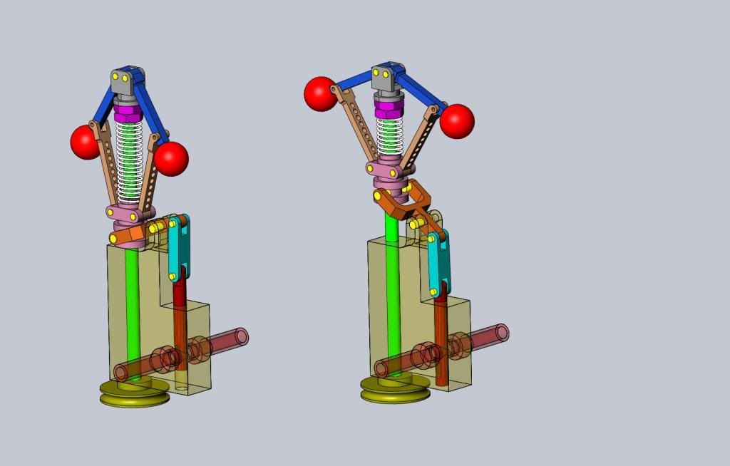
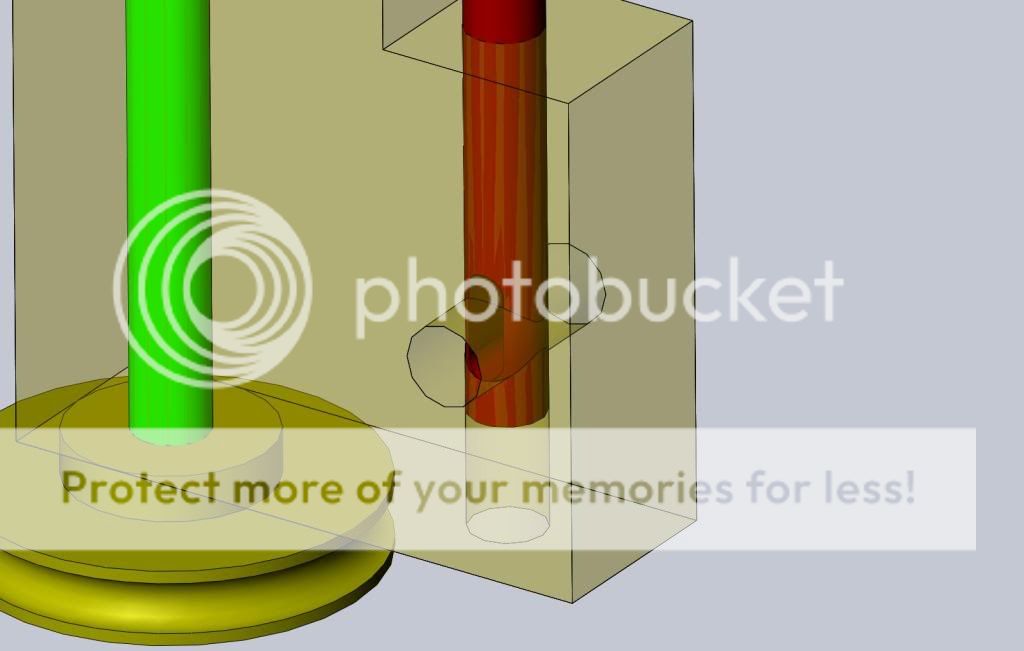
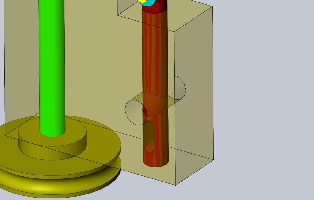
No machining this morning. I have been designing the valve mechanism that the governor operates, and making the lever a little mor machining friendly. I made the valve block and inlet/outlet tubes transparent, so you can see how it works. At very low speed or when stopped, the governor has a 'balls in" attitude, and the valve is completely open, giving no restriction to the passage of air or steam into the cylinders. As soon as the engine revs up, centrifugal force begins to move the governor into a "balls out" attitude. This causes the valve to progressively close the air/steam port untill at full "balls out" the valve is completely closed. I have also attached 2 "blown up views" of the steam port totally open and totally closed, as it is hard to see in the bigger view.


Marv---Come on, my better half is getting old like me. I don't get that "thermal agitation" thing near as often as I used to!!! ;D ;D ;Dmklotz said:Brian's in luck on the increased noise at higher ISO numbers issue. Much of the noise is due to thermal agitation and so, lower ambient temperatures mean less noise.
I'm told that the folks in Canada have a real lock on low ambient temperatures.
- Joined
- Jun 4, 2008
- Messages
- 3,294
- Reaction score
- 636
The "full balls out" position would be with the balls at almost 90 degrees. If the spring/jam nuts allow them to get higher than down in the drawing you might have a situation where the pivot collar can escape. Obviously something that's easy to check.
Looks like a lot of "fiddly parts" for someone like me who doesn't like them either. ;D
Looks like a lot of "fiddly parts" for someone like me who doesn't like them either. ;D
Since the main supporting block is aluminum, and there is a (lot?) of wear from the revolving stem post and the sliding valve rod, I have opened the bores in the aluminum out to .3125" and put in a full length brass bushing in both places. I also noticed that by the time I was finished that I had an air lock at the bottom of the sliding valve, so I have extended a bleed hole down and out thru the side of the main body. In theory, pressurized air should never reach that bleed port (except for any leakage past the end of the valve), but it will keep the valve from "air locking" when it moves down in the bore.
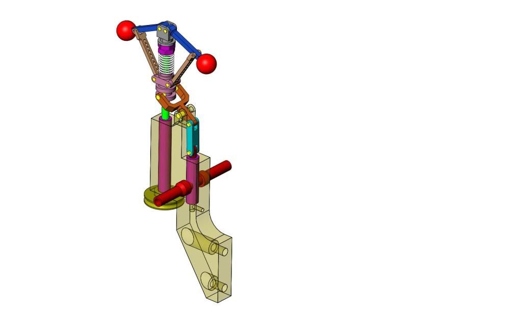

Tel--There is a tricky bit you can't see. The valve has a slot thru it, with a solid peice between the slot and the lower end. See the blow ups in the previous posts.
Going to end up something like this---


Similar threads
- Replies
- 90
- Views
- 9K
- Replies
- 3
- Views
- 2K
- Replies
- 19
- Views
- 6K


