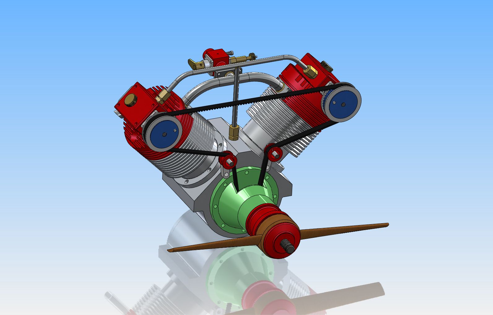
Nemett Lynx 15 cc 4 Stroke I/C Petrol Engine

Home Model Engine Machinist Forum

Help Support Home Model Engine Machinist Forum:

This site may earn a commission from merchant affiliate links, including eBay, Amazon, and others.
Zega79, I have the drawings for this motor and will start later this year. As Mike said, you have to make your own tolerances. Just work out what is easier, to make bores on size or to make the parts that go in them on size, and make other parts to suit.

Paul.

Good advice given. The Lynx will be in the que after two old engine projects,namely Bolero and Firefly both have yet to be completed and run. Reason was -----lack experience to handle the unforgiving fits required.
Now in South Thailand after the Burma Bank Fishing Trip. Due a temporary ban
,we were forced to go to other spots which overfished and hence not very productive. Catch was bad with nothing great to crow.
 
While in South Thailand,to kill idle time,made B.O.M. and ordered some cut bar stocks .
For this project,will take time to study plans, Model Engineer Mag.Nemett-Lynx Article.
The author has lined up priority que for parts to be made.Messing up priority order will bring disorders as some parts need to pair up and fit in mutually.Will start with liner. Liner will be used
to closely slide fit cylinder jacket and in turn same jacket to fit crankcase etc etc. to optimise heat transfer.

IMG_2606.jpg
 
Last edited:
Collected bar stocks. Come next week will begin the begin. Will try hard not goofing. Salvaging a job is time consuming/stressful and time consuming.Bought more enough to build three engines.
Will start off as recommended to turn the cast iron liner and from here the cylinder jacket,cranlcase etc.
In these order the related vital fits met.

IMG_0635.jpg
 
Hi Gus,
If you want to build the Lynx from the article in "Best of Model Engineer Vol 3" you should be aware that table for generating the cam was left out.

This thread on Model Engineer Forum contains the relevant information including a link to the original article in Model Engineer Sept 2006 page 282.

Clive
 
  • Like
Reactions: gus
Gus
If you want a copy of the page that was missing I have the original drawings and would be happy to email you a copy of the missing page

Mike
 
  • Like
Reactions: gus
Tell me--Does this engine have a sealed crankcase? I have now built 6 open crankcase engines, and the oil mess drives me crazy each time I run them. If the crankcase is sealed, does it have splash oiling, or are there oil passages drilled in the crankshaft?---Brian
 
Tell me--Does this engine have a sealed crankcase? I have now built 6 open crankcase engines, and the oil mess drives me crazy each time I run them. If the crankcase is sealed, does it have splash oiling, or are there oil passages drilled in the crankshaft?---Brian

Has over-hung crankshaft and grease packed bearings.Still studying and asking questions. Been working on air compressors,lube oil in the crankcase leaking out is messy. Seen several engines running on YouTube.

I seen nothing sticking out from the con-rod big end.W/o which splash lubrication not well done. There is a breather tube from crankcase to OHC housing to lubricate cams.

Paul and Gus will be building this engine. Will be fun.Paul will lead Gus.
Gus will follow Paul.
 
The con rod big end dips into the oil so that splashes it about and there is no need for a separate splasher.

Top end is lubricated by oil vapour going up the copper bit that joins the breather to the box the cam is in.
 
Tell me--Does this engine have a sealed crankcase? I have now built 6 open crankcase engines, and the oil mess drives me crazy each time I run them. If the crankcase is sealed, does it have splash oiling, or are there oil passages drilled in the crankshaft?---Brian

Brian

It may be sealed but it does leak. I'm using a Walbro carb so need some crank case pressure for the pump. Net result is the oil migrates through the nose bearings, then on to the toothed belt, which then is lifted upwards to the camshaft. On the way the prop draft catches it then its blown aft. (yes there are oil seals on the bearings, but I don't wnat to glue them in. As soon as I do I'll need a strip down)

That's the oil that doesn't creep past the rings and out the exhaust. There's no oir scraper ring.

Who was it that was asking questions about fits?

Pete
 
  • Like
Reactions: gus
The con rod big end dips into the oil so that splashes it about and there is no need for a separate splasher.

Top end is lubricated by oil vapour going up the copper bit that joins the breather to the box the cam is in.


Thanks Jason.

Please advise oil level. Planning to put in an Ingersoll-Rand Oil Level Sight Glass.. Now trying to finish up DIY Tool Cabinet .
 
The big end uses a needle bearing so it doesn't need much oil. When buying bearings be certain that they are of the contact seal variety. What look like rubber seals can be non-contact shields and will not hold any oil. Even contact seals won't be able to hold back the oil in a closed single cylinder crankcase due to the constantly fluctuating pressure. You could add a shaft oil seal in front of the rear crank bearing to prevent oil from leaking out.

Greg
 
Gus---I sent you a private message about this about 5 minutes ago.---Brian EDIT--Gus--I followed this link, and there are a lot of folks saying that the magazine article has a lot of mistakes in it, and that anyone considering building this engine should buy the plans, not rely on the magazine articles. Model Engineer Forum
 
Last edited:
Brian its the earlier 2006 edition that has a few errors, The one that Gus has in the "Best of" uses the revised drawings. Its only a bit of text in the Best of that does not agree with the drawings and the missing cam details that have already been covered.

Some useful photos

here and here

J
 
Last edited:
I built it from the "Best of Magazine" with few problems. Of course the missing cam data didn't help but Jason helped me out there. All the notes are contained in this thread

http://www.model-engineer.co.uk/forums/postings.asp?th=90027&p=1

3-042_zpsbf888bcf.jpg


3-045_zpsadba1bf1.jpg


Malcolm’s write up is very well done and makes it easy for a beginner to work out what they need to do.

Pete
 
Brian

I like your drawing, Jason had mentioned doing something similar. I had thought the Bobcat would easily be made as a flat 4 'boxer'. Although the problem with oil passing the pistons could prove an issue.

Pete
 
Hi Gus,
If you want to build the Lynx from the article in "Best of Model Engineer Vol 3" you should be aware that table for generating the cam was left out.

This thread on Model Engineer Forum contains the relevant information including a link to the original article in Model Engineer Sept 2006 page 282.

Clive

My copy of the magazine certainly has the cam calcs, I have copied and enlarged all the drawings from the magazine to A3 size, that way it doesn't matter if they get dirty or damaged.

Paul.
 
I built it from the "Best of Magazine" with few problems. Of course the missing cam data didn't help but Jason helped me out there. All the notes are contained in this thread

http://www.model-engineer.co.uk/forums/postings.asp?th=90027&p=1

3-042_zpsbf888bcf.jpg


3-045_zpsadba1bf1.jpg


Malcolm’s write up is very well done and makes it easy for a beginner to work out what they need to do.

Pete

Hi Pete,
You are my hero/meister. When can we see video of running engine?
Will be late next week to start turning the C.I. Liner. Will proceed step by step as per Best of Magazine. Paul Swifty is about to get started.

Would you be running with dry crankcase or lube oil topped up Crankcase?.
 
I really do like the way the crankcase is machined from a block of aluminum in that design, and intended to be "oil-tight" (even if it really isn't according to posters.). I know that the timing belt drive for the camshaft works very well, because that is what I used on the Atkinson engine I built, but its a bit too "new age" for my taste.--Its probably just my age, but I like to see push rods pushing and rocker arms rocking. I'm not horribly impressed with the cantilevered crankshaft and no flywheel. The engine looks like a large model airplane engine, and that is not a bad thing---its just that I prefer a more industrial look. I am probably going to take that design and model/design a more industrial looking engine from it. This may not happen quickly, but it is probably the direction I will move in.---Brian
 
Pete, my opposed twin is under way so I'll let you know how the oil goes regarding the pistons and tappet guides.

Brian, I spent last weekend milling out the crankcase, first drilled to 1" dia then bored to 46mm on the lathe and finally milled to 47x48 x 57mm deep

J
 
Love reading all the "private" thoughts, and comments from the more experienced engine builders. I marvel that they can look at a basic concept, then, add cylinders, V-Twin it, add push-rods - where none existed, and revamp the whole shebang until it morphs into a "new" design. Love the re-worked, computer renderings, and all the thinking-out-loud from the expert swarf-makers.

Congratulations, and thanks for sharing this build with us. Guys like you advance this hobby.


Frank
 

Latest posts

Back
Top