Here is tonights instalment. Its quite hard to get motivated to get out there initially after being at work all day but once I get out there I dont want to come back in! Came in at about 11:20 tonight, got a reasonable bit done.
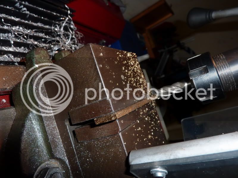
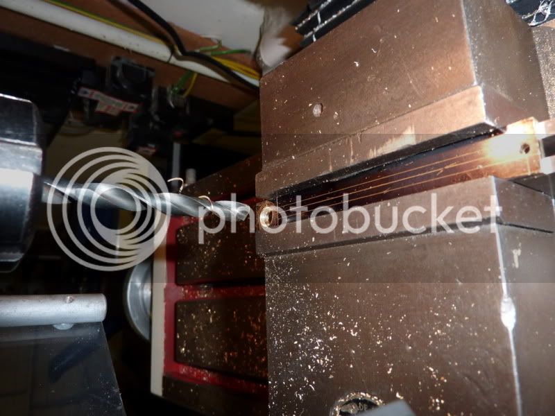
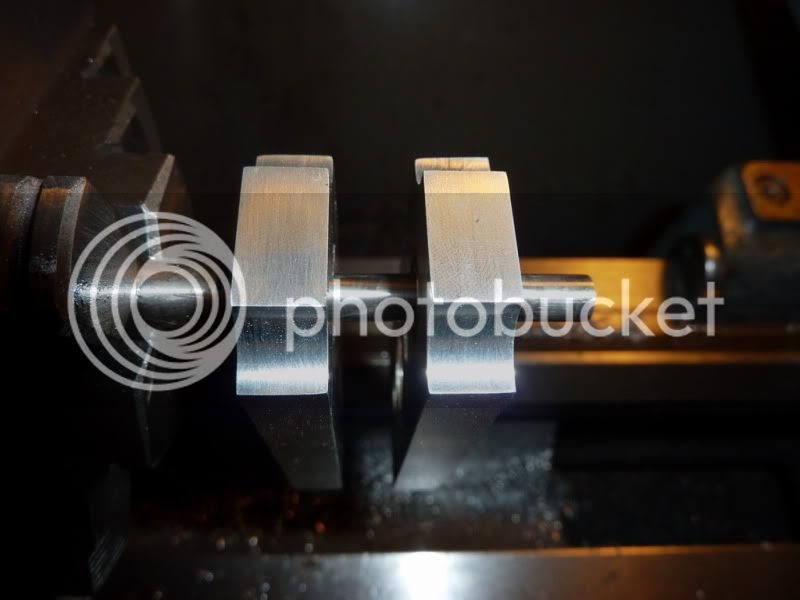
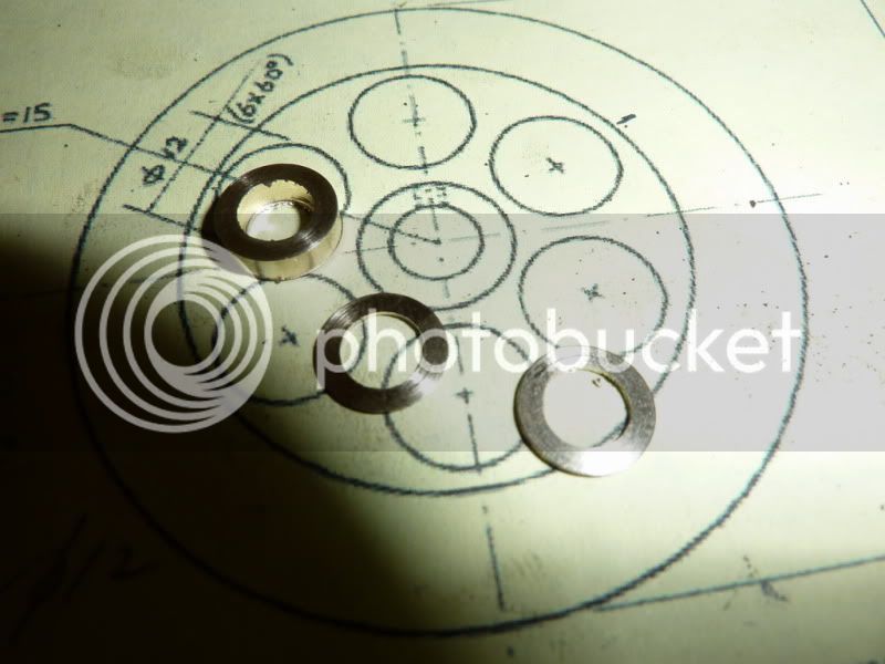
First I thought Id measure the 12mm end mill to see if it was actually a 12mm it was! So I decided to put it in the vice and try opening the bearing housings by hand:
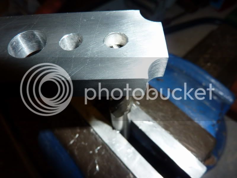
To my surprise it worked a treat nice push fit:
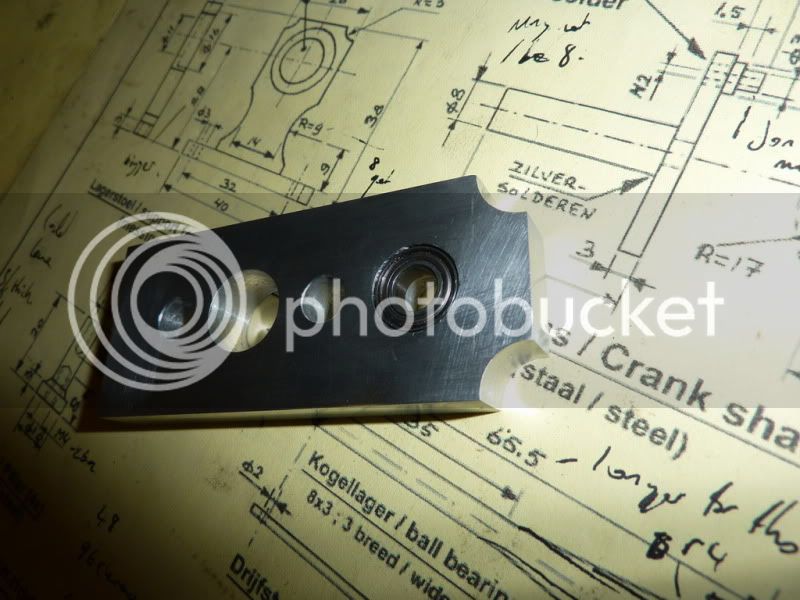
I decided to put a dab of loctite on them; they will never be coming back out.
So with that bit quickly done, I was feeling quite good and made a start on the crankshaft. I decided I would do it my old way, but with more care and attention threaded shaft, disc and pin.
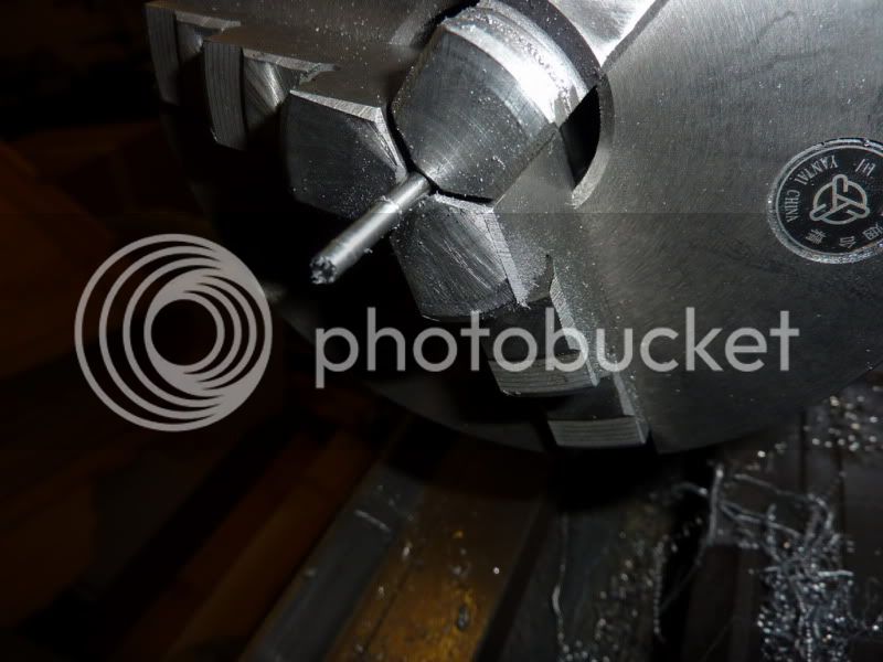
Started by facing off the stock (think this is either 32mm stainless or some sort of chromium steel I was given at work) it seems to machine quite nicely whatever it is. I then drilled and tapped 3/16 x 40 tpi.
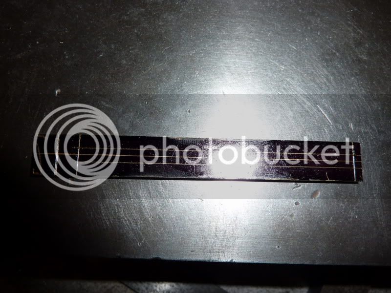
I didnt fancy my chances of parting off am a bit nervous about doing steel for some reason, it starts to make squeaking noises then I get the hacksaw out! Anyway, it was sticking way to far out of the chuck for parting off. Getting it closer to the chuck would have meant another saw cut since it didn't fit through the chuck body. So this time I just skipped a step and went for the hacksaw which is now pretty blunt!
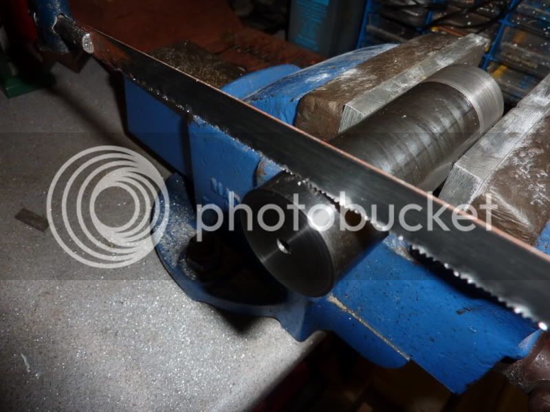
About 10 mins later I had this:
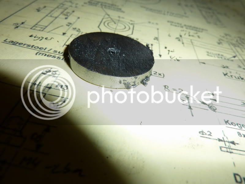
I was pretty happy with that straight cut and the finish was ok, so I thought Id just leave it!
Lol, just checking youre awake, of course it would be screwed to the shaft and faced off later!
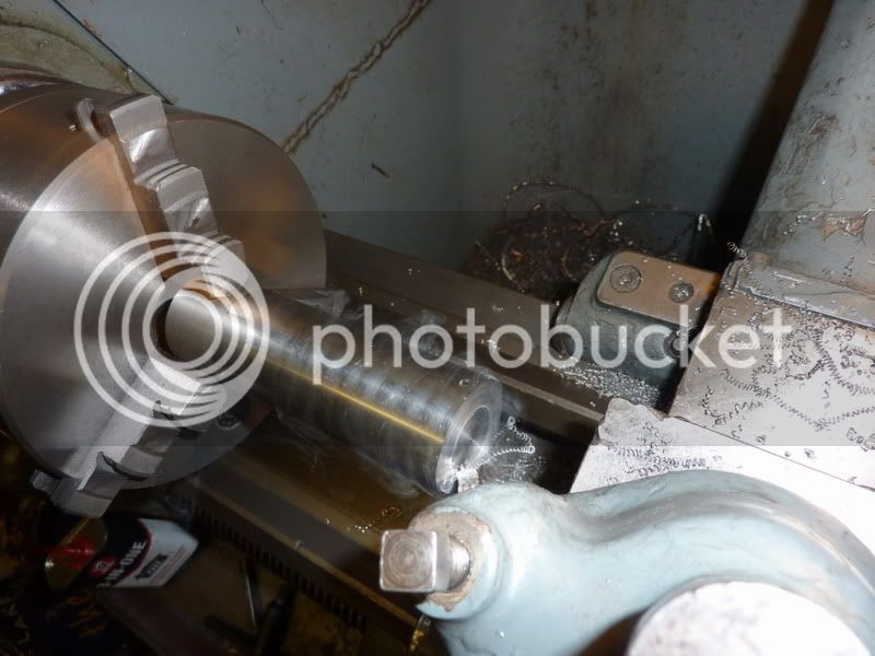
Started machining down some 10mm stainless for the shaft.
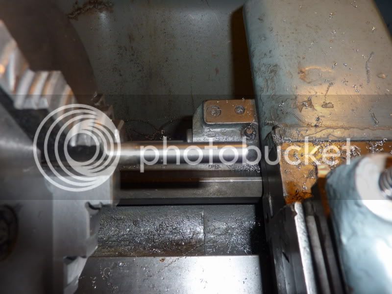
It cuts really nicely, think its 303 or 304. The metal comes of in long spirals:
In fact on one of the cuts it was one continuous piece of swarf
Taking finishing cuts and lots of passes at the same setting. I had a bit of a flexing issue so the end furthest from the chuck was always larger this makes it hard to test fit in the bearings. Consequently it is a marginally looser fit on the end near the chuck that I would have liked, no play but just a sliding fit rather than a push fit. I contemplated buying some 6mm bar but I think it would have needed reducing marginally to fit the bearings anyway.
I turned the shoulder for the thread and gave it an undercut with the hack saw dodgy I know but a parting tool wouldnt work that far out from the chuck.
Then I put the 3/16 x 40 Tpi thread on. This engine is a bit mix & match on the sizes. It was originally designed in metric so for the first time I am trying to stick to that, but all my taps and dies are imperial or BA and some of my metal was imperial! Oh, and my machines, so theres been a bit of conversion going on! I used to always use imperial but I think I actually prefer metric now if I had DROs I definitely would.
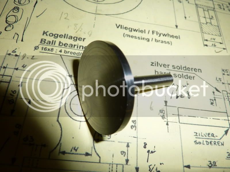
Crankdisc screwed on and loctited in place.
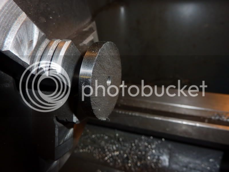
Facing disc down to thickness. This also gets it square to the shaft if there is any misalignment in the threads. The back face doesnt matter as long as it doesnt catch on anything but there doesnt appear to be much misalignment anyway.
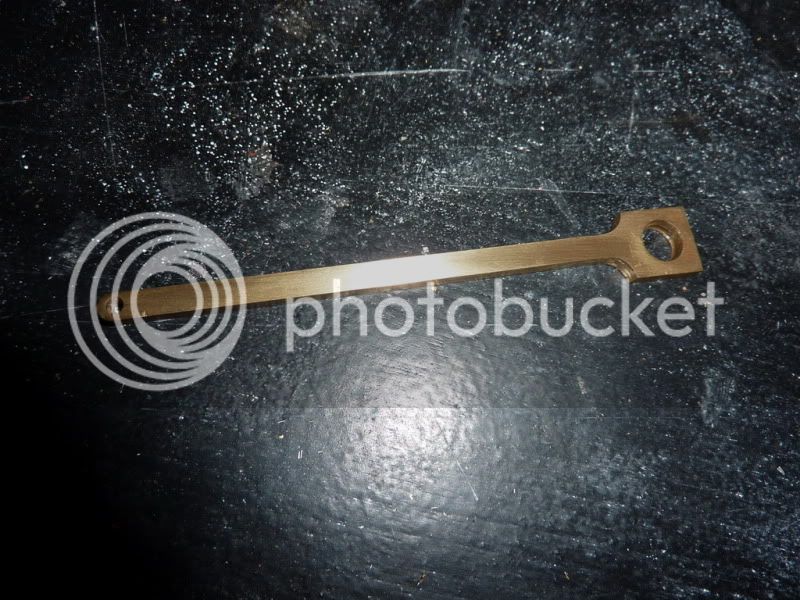
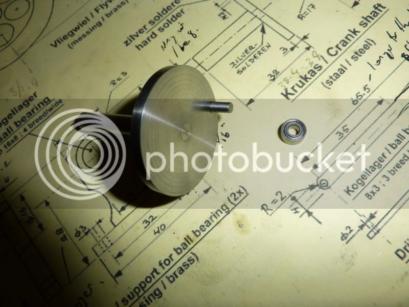
Bit of a polish with some wet & dry and here is the crankshaft / disc.
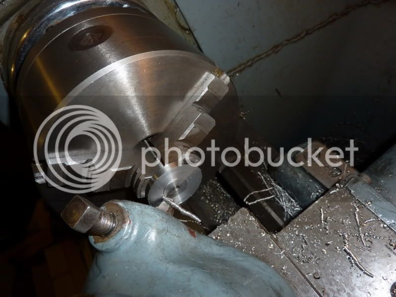
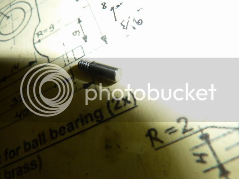
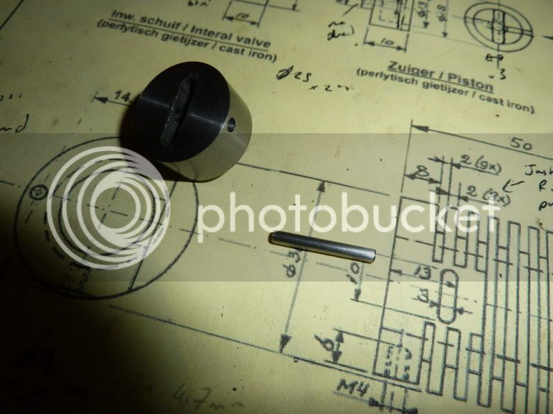
Next I turned the crankpin which is 3mm. I decided to use some 1/8 silver steel for this, it didnt need to be silver steel, just about anything would do, it was just the nearest size I had.
Turned the slightly smaller shoulder and threaded 6ba, dont think I took a photo of that.
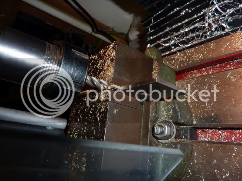
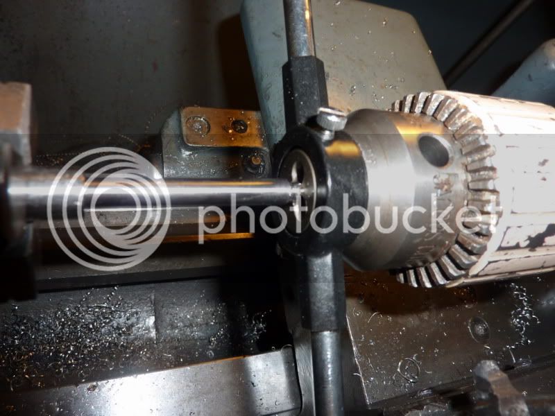
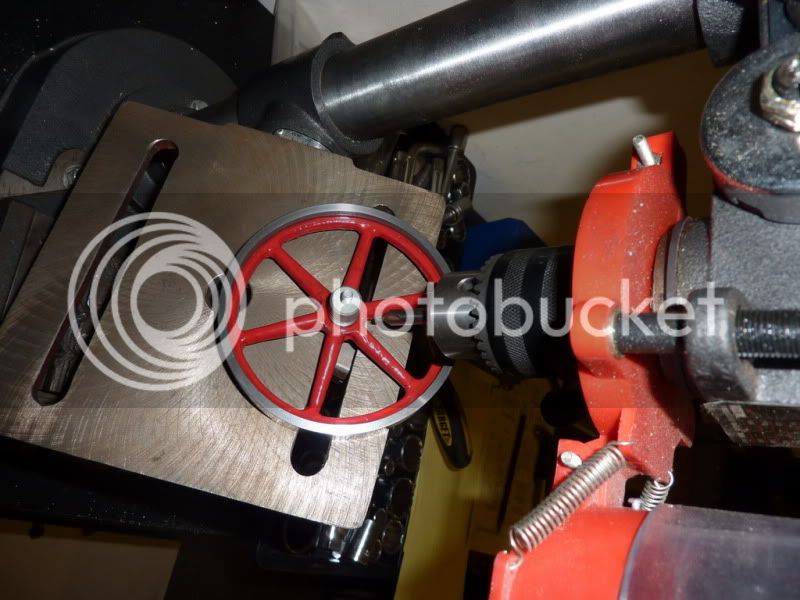
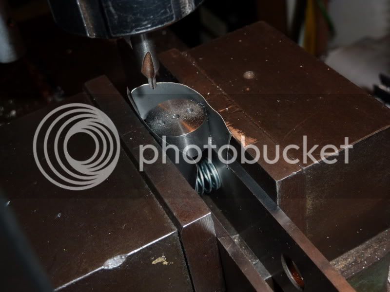
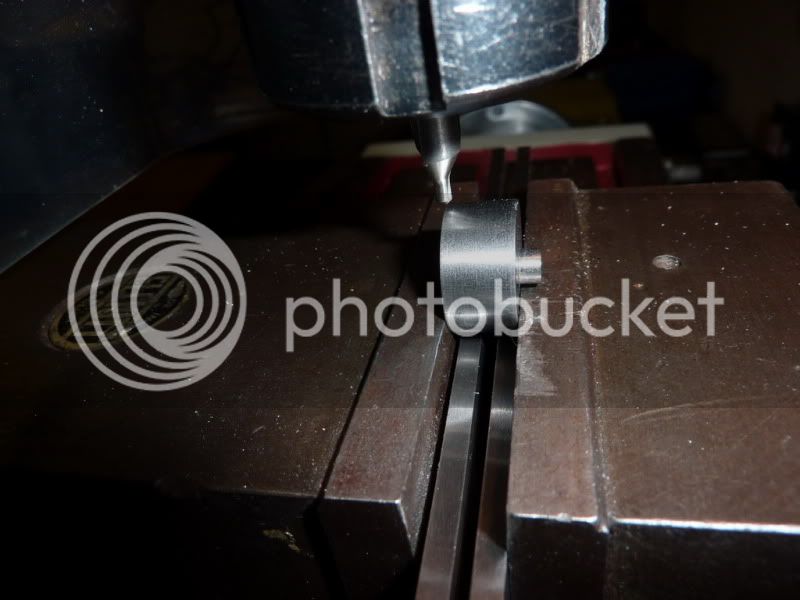
I set the crankshaft / disc up in the milling machine to drill & tap the hole for the crank pin. To do this I just aligned the centre drill by eye to the centre pip then wound the table out 13.5mm which is the throw.
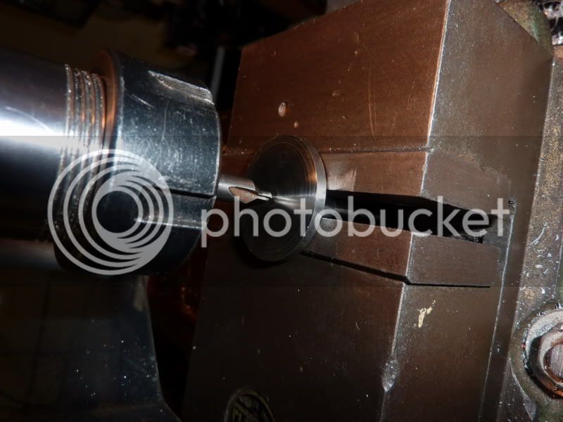
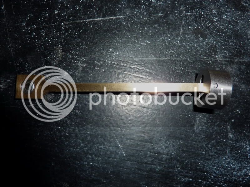
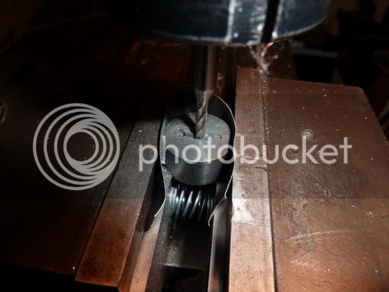
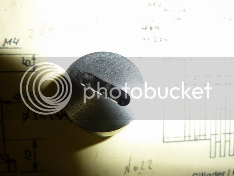
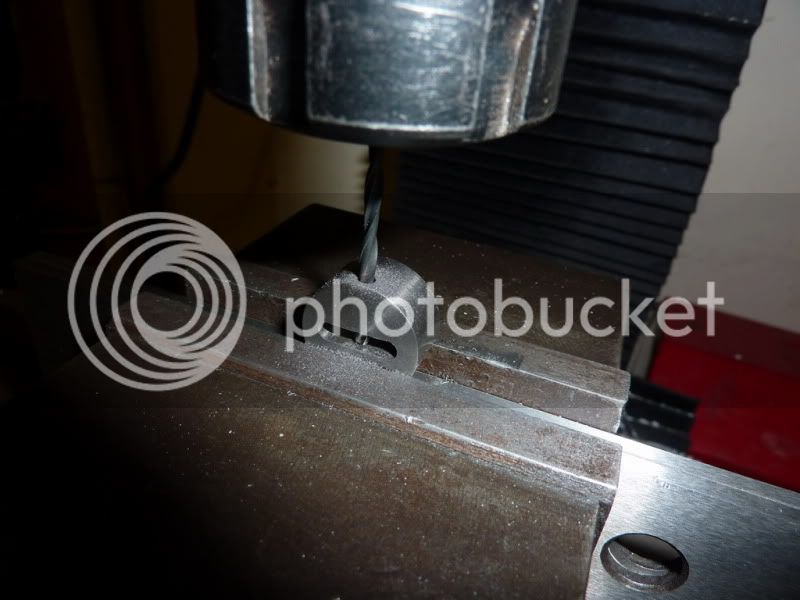
Centre drilled, then drilled and tapped 6ba. Screwed and loctited the pin in place:
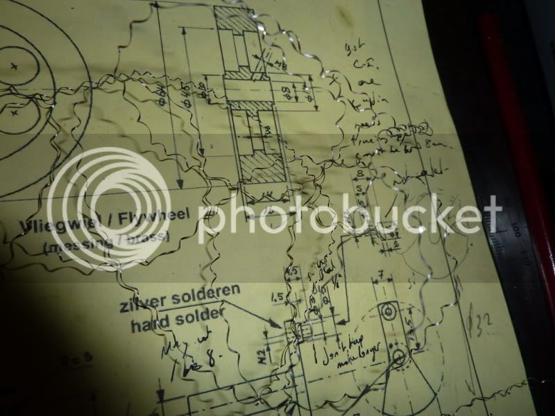
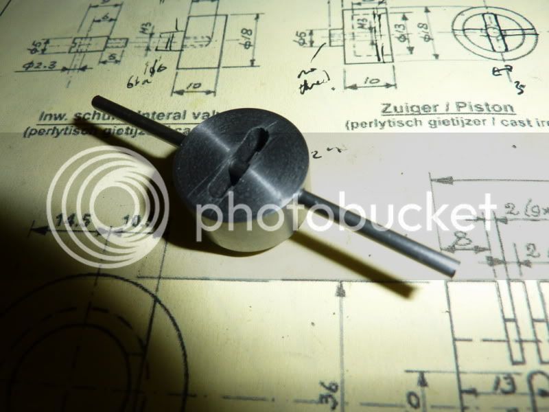
Some of you will notice Ive deviated from the drawings here. Ive just got a pin sticking out rather than a special shoulder and screw that clamps together. The cylinder / bearing housings will be arranged on the baseplate such that the big end bearing is positioned in the centre of the crank pin (1.5mm space either side) but it is free to slide which should allow it to account for any out of squareness without binding. It would probably be better practice to do it the way Jan has in his drawings but this is the same method I used on my stirling engine and it seemed to work on that so Ill give it a go here. If not, I can easily make up a spacer and a screw to make it rigid.
I'm also not bothering with any balancing. I think the pin / big end is light enough and the flywheel sufficiently heavy not to make a difference on this design.
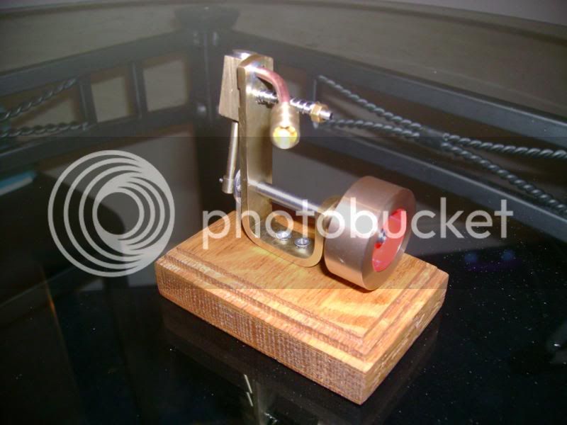
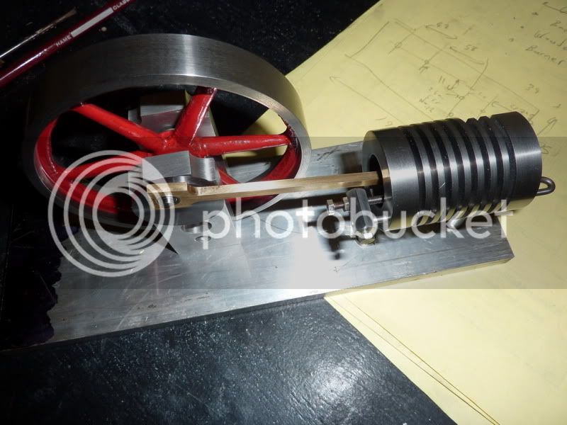
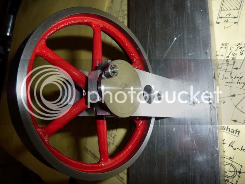
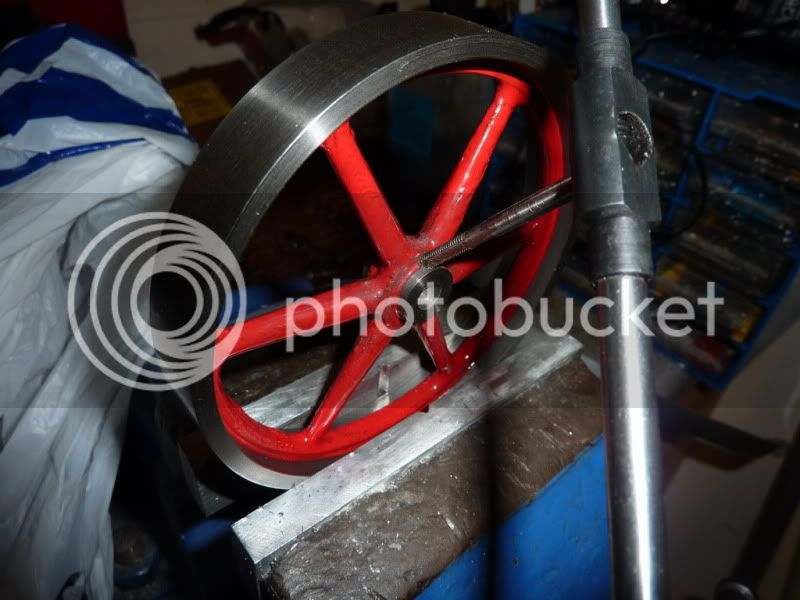
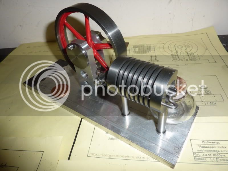
Quick test assembly:
I still need to machine the slot and hole in the piston, make the conrod, make the base plate, a base from brown stuff and now I think a burner. I was planning to use the glass burner from my chemistry set I had when I was about 10 but its a sort of bulb shape and interferes with the cylinder columns so I dont think I will be able to manoeuvre the flame into the correct position with that one. Not sure whether to solder a burner or machine one from solid alloy as I did with my stirling. This will need a lot more fuel though so think I may solder it to save time boring stuff out!
Got one eye on the finishing line but am determined not to attempt any start up until its completely finished!
Nick
First I thought Id measure the 12mm end mill to see if it was actually a 12mm it was! So I decided to put it in the vice and try opening the bearing housings by hand:
To my surprise it worked a treat nice push fit:
I decided to put a dab of loctite on them; they will never be coming back out.
So with that bit quickly done, I was feeling quite good and made a start on the crankshaft. I decided I would do it my old way, but with more care and attention threaded shaft, disc and pin.
Started by facing off the stock (think this is either 32mm stainless or some sort of chromium steel I was given at work) it seems to machine quite nicely whatever it is. I then drilled and tapped 3/16 x 40 tpi.
I didnt fancy my chances of parting off am a bit nervous about doing steel for some reason, it starts to make squeaking noises then I get the hacksaw out! Anyway, it was sticking way to far out of the chuck for parting off. Getting it closer to the chuck would have meant another saw cut since it didn't fit through the chuck body. So this time I just skipped a step and went for the hacksaw which is now pretty blunt!
About 10 mins later I had this:
I was pretty happy with that straight cut and the finish was ok, so I thought Id just leave it!
Lol, just checking youre awake, of course it would be screwed to the shaft and faced off later!
Started machining down some 10mm stainless for the shaft.
It cuts really nicely, think its 303 or 304. The metal comes of in long spirals:
In fact on one of the cuts it was one continuous piece of swarf
Taking finishing cuts and lots of passes at the same setting. I had a bit of a flexing issue so the end furthest from the chuck was always larger this makes it hard to test fit in the bearings. Consequently it is a marginally looser fit on the end near the chuck that I would have liked, no play but just a sliding fit rather than a push fit. I contemplated buying some 6mm bar but I think it would have needed reducing marginally to fit the bearings anyway.
I turned the shoulder for the thread and gave it an undercut with the hack saw dodgy I know but a parting tool wouldnt work that far out from the chuck.
Then I put the 3/16 x 40 Tpi thread on. This engine is a bit mix & match on the sizes. It was originally designed in metric so for the first time I am trying to stick to that, but all my taps and dies are imperial or BA and some of my metal was imperial! Oh, and my machines, so theres been a bit of conversion going on! I used to always use imperial but I think I actually prefer metric now if I had DROs I definitely would.
Crankdisc screwed on and loctited in place.
Facing disc down to thickness. This also gets it square to the shaft if there is any misalignment in the threads. The back face doesnt matter as long as it doesnt catch on anything but there doesnt appear to be much misalignment anyway.
Bit of a polish with some wet & dry and here is the crankshaft / disc.
Next I turned the crankpin which is 3mm. I decided to use some 1/8 silver steel for this, it didnt need to be silver steel, just about anything would do, it was just the nearest size I had.
Turned the slightly smaller shoulder and threaded 6ba, dont think I took a photo of that.
I set the crankshaft / disc up in the milling machine to drill & tap the hole for the crank pin. To do this I just aligned the centre drill by eye to the centre pip then wound the table out 13.5mm which is the throw.
Centre drilled, then drilled and tapped 6ba. Screwed and loctited the pin in place:
Some of you will notice Ive deviated from the drawings here. Ive just got a pin sticking out rather than a special shoulder and screw that clamps together. The cylinder / bearing housings will be arranged on the baseplate such that the big end bearing is positioned in the centre of the crank pin (1.5mm space either side) but it is free to slide which should allow it to account for any out of squareness without binding. It would probably be better practice to do it the way Jan has in his drawings but this is the same method I used on my stirling engine and it seemed to work on that so Ill give it a go here. If not, I can easily make up a spacer and a screw to make it rigid.
I'm also not bothering with any balancing. I think the pin / big end is light enough and the flywheel sufficiently heavy not to make a difference on this design.
Quick test assembly:
I still need to machine the slot and hole in the piston, make the conrod, make the base plate, a base from brown stuff and now I think a burner. I was planning to use the glass burner from my chemistry set I had when I was about 10 but its a sort of bulb shape and interferes with the cylinder columns so I dont think I will be able to manoeuvre the flame into the correct position with that one. Not sure whether to solder a burner or machine one from solid alloy as I did with my stirling. This will need a lot more fuel though so think I may solder it to save time boring stuff out!
Got one eye on the finishing line but am determined not to attempt any start up until its completely finished!
Nick


![DreamPlan Home Design and Landscaping Software Free for Windows [PC Download]](https://m.media-amazon.com/images/I/51kvZH2dVLL._SL500_.jpg)