
You are using an out of date browser. It may not display this or other websites correctly.
You should upgrade or use an alternative browser.
You should upgrade or use an alternative browser.
My Flame Gulper
- Thread starter NickG
- Start date


Help Support Home Model Engine Machinist Forum:
This site may earn a commission from merchant affiliate
links, including eBay, Amazon, and others.
Tonight I made the effort to get a little bit done. I am travelling down to south wales tomorrow, it's going to be a long day, up at 4:30am to get an early flight, I'll be back about 9pm and don't think I'll be up for the workshop - besides, it would actually be dangerous.
I had a look at the drawing of the striker / valve adjustment and it looked unnecessarily complex to me, so I decided to do it slightly differently and by the same method Bogstandard used on his. No machining to show as it was very straightforward lathe work.
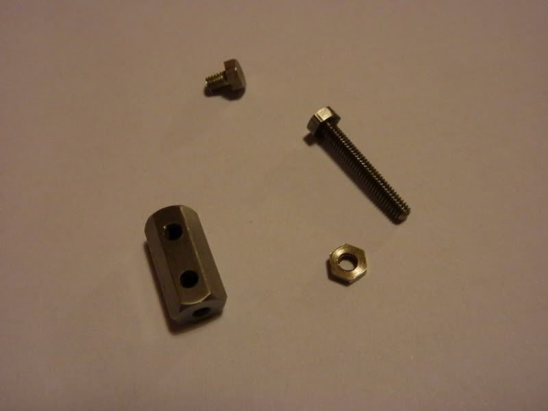
I took a bit of hex bar, faced down to length. Drilled and tapped a 6ba thread in one end about 5mm deep, enought to break into the cross hole for the rod. Then into the milling machine to cross drill the rod hole and drill and tap the striker hole 6ba.
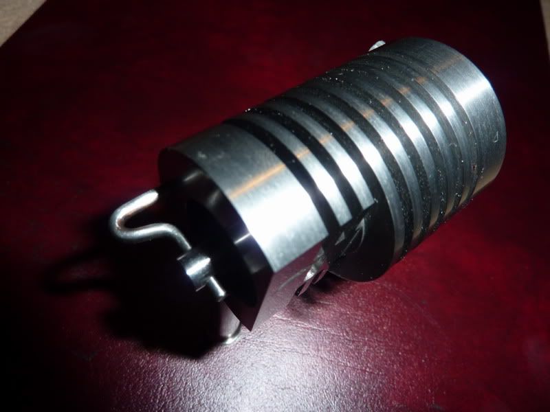
Here are the parts including a long 6ba bolt (striker), lock nut and a short 6ba bolt to clamp it onto the rod:
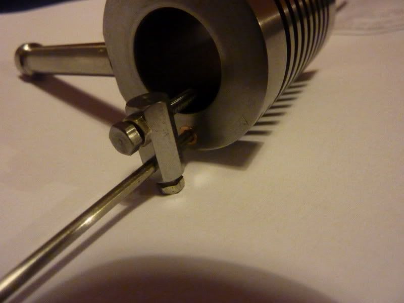
Here it is assembled, need to make the rod next!
For those that aren't familiar with this design it's easier to just say have a look here: http://heetgasmodelbouw.ridders.nu/Webpaginas/pagina_happer_inw_schuif/inw_schuif_frameset.htm
Coming along, al-be-it a little slowly!
Nick
I had a look at the drawing of the striker / valve adjustment and it looked unnecessarily complex to me, so I decided to do it slightly differently and by the same method Bogstandard used on his. No machining to show as it was very straightforward lathe work.
I took a bit of hex bar, faced down to length. Drilled and tapped a 6ba thread in one end about 5mm deep, enought to break into the cross hole for the rod. Then into the milling machine to cross drill the rod hole and drill and tap the striker hole 6ba.
Here are the parts including a long 6ba bolt (striker), lock nut and a short 6ba bolt to clamp it onto the rod:
Here it is assembled, need to make the rod next!
For those that aren't familiar with this design it's easier to just say have a look here: http://heetgasmodelbouw.ridders.nu/Webpaginas/pagina_happer_inw_schuif/inw_schuif_frameset.htm
Coming along, al-be-it a little slowly!
Nick
modeng2000
Well-Known Member
- Joined
- Nov 14, 2008
- Messages
- 150
- Reaction score
- 40
For my striker/valve fitting I stuck to the original design fairly closely because I was concerned about any increase in the weight of moving parts. After all the engine has barely enough power to run its self!
John
John
This is true, that's the only reason I can think that Jan made that parts like that, but then I thought the extra friction from another couple of grams on that isn't going to make any difference. Also mine should gice less drag with the short bronze bushes as opposed to contact all the way through the cylinder fins (hopefully!)
I also now know that Bogstandards works with this striker so that gave me confidence to do it, if the engine doesn't run, I don't think that will be the problem, probably just my dodgy workmanship :-\
I also now know that Bogstandards works with this striker so that gave me confidence to do it, if the engine doesn't run, I don't think that will be the problem, probably just my dodgy workmanship :-\
modeng2000
Well-Known Member
- Joined
- Nov 14, 2008
- Messages
- 150
- Reaction score
- 40
Good luck NickG, if you don't try you'll never know.
John
John


$40.02
$49.99
Becker CAD 12 3D - professional CAD software for 2D + 3D design and modelling - for 3 PCs - 100% compatible with AutoCAD
momox Shop


$24.99
$34.99
Bowl Sander Tool Kit w/Dual Bearing Head & Hardwood Handle | 42PC Wood Sander Set | 2" Hook & Loop Sanding Disc Sandpaper Assortment | 1/4" Mandrel Bowl Sander for Woodturning | Wood Lathe Tools
Peachtree Woodworking Supply Inc


![DreamPlan Home Design and Landscaping Software Free for Windows [PC Download]](https://m.media-amazon.com/images/I/51kvZH2dVLL._SL500_.jpg)
$0.00
DreamPlan Home Design and Landscaping Software Free for Windows [PC Download]
Amazon.com Services LLC


$29.95
Competition Engine Building: Advanced Engine Design and Assembly Techniques (Pro Series)
Amazon.com Services LLC


Thanks John, Arnold and Dean :bow:
Hopefully I'll get a little bit more done tonight.
John, I'm thinking of how best to tackle the bent valve rod, did you do it as per drawing and if so did you have a special jig or just go for it in the vice with a bit of rod to get the radius?
Thanks,
Nick
Hopefully I'll get a little bit more done tonight.
John, I'm thinking of how best to tackle the bent valve rod, did you do it as per drawing and if so did you have a special jig or just go for it in the vice with a bit of rod to get the radius?
Thanks,
Nick
modeng2000
Well-Known Member
- Joined
- Nov 14, 2008
- Messages
- 150
- Reaction score
- 40
Hi Nick,
I used a piece of silver steal and heated it red hot before bending it in two stages. I tried to copy the drawing fairly closely. First a 180 deg. bend using a suitable piece of bar as a former and then by heating one leg of the bent rod, made the second 90 deg. bend with the same former. Any misalignment is easily corrected and then a quick polish and there you have it.
Remember to leave enough rod for the long leg, I ended up making two because my bend was in the wrong place along the rod. ???
John
modeng2000
Well-Known Member
- Joined
- Nov 14, 2008
- Messages
- 150
- Reaction score
- 40
Good luck Nick.
John
John
Hi again,
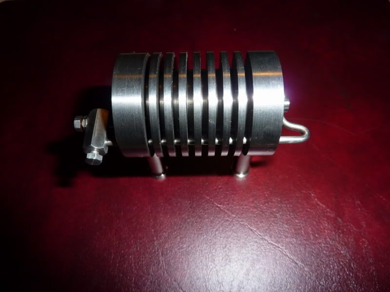
I got tiny bit more done on this. I decided to bend the valve rod like John did. I can see why it was done like that, I just don't like bending things though! Anyway, I fannied on for about an hour or so with this but it produced a decent result, not quite to drawing but ok. I left the short bit longer than Jan had on his drawings and glad I did, I think it looks just right:
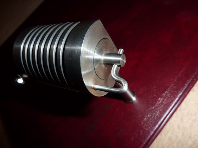
I drilled the cross hole in the piston about 0.2mm oversize and the rod length was a few mm longer I think because of the hex striker block. Anyway, it's not critical, I know it's ok at the 2 extremes, the adjustment can be done with the bolt and the pinch bolt. It's a nice smooth sliding fit, hardly any friction there so looking good at the mo.
I also got the bearings hacksawed out and marked so starting on those tomorrow night.
Nick
I got tiny bit more done on this. I decided to bend the valve rod like John did. I can see why it was done like that, I just don't like bending things though! Anyway, I fannied on for about an hour or so with this but it produced a decent result, not quite to drawing but ok. I left the short bit longer than Jan had on his drawings and glad I did, I think it looks just right:
I drilled the cross hole in the piston about 0.2mm oversize and the rod length was a few mm longer I think because of the hex striker block. Anyway, it's not critical, I know it's ok at the 2 extremes, the adjustment can be done with the bolt and the pinch bolt. It's a nice smooth sliding fit, hardly any friction there so looking good at the mo.
I also got the bearings hacksawed out and marked so starting on those tomorrow night.
Nick
That bent rod looks good, Nick. The whole assembly looks very nice!
Doing a rod like this often gives me trouble, and I usually end up doing it more than once to get it right, especially when you have a piece that has a "good" 90 deg angle involved. Well done.
Dean
Doing a rod like this often gives me trouble, and I usually end up doing it more than once to get it right, especially when you have a piece that has a "good" 90 deg angle involved. Well done.
Dean
Nick,
Just joined and saw your post. I started on the same engine a few days ago. This will be my first engine of any type so I'm really glad to be able to follow your progress. Great pictures and descriptions. Should really help me a lot.
Mike aka groundhog
Just joined and saw your post. I started on the same engine a few days ago. This will be my first engine of any type so I'm really glad to be able to follow your progress. Great pictures and descriptions. Should really help me a lot.
Mike aka groundhog
Cheers Dean, I never get bends right, this is probably the best one I've done!
Mike,
You will see I've made a few mistakes already! Hope it can be of some help, I'm losely following the drawings but making it fit with the materials I bought / had and a flywheel I already had. I just hope it works!
I hope you will be posting your progress up too?
Nick
Mike,
You will see I've made a few mistakes already! Hope it can be of some help, I'm losely following the drawings but making it fit with the materials I bought / had and a flywheel I already had. I just hope it works!
I hope you will be posting your progress up too?
Nick
modeng2000
Well-Known Member
- Joined
- Nov 14, 2008
- Messages
- 150
- Reaction score
- 40
Nick,
Glad it worked for you, the rod looks fine.
John
Glad it worked for you, the rod looks fine.
John
Thanks John,
Got a bit more done last night, but didn't all go to plan - you'll see below! I was planning to get another bit done tonight but for some reason my 3 1/2 year old son has only just gone to bed, the wife went ages agio and left me with him! Normally he's asleep by about 19:30 and it's 22:55 now!
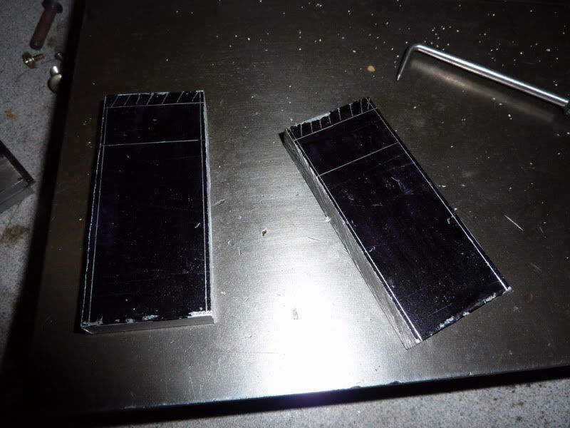
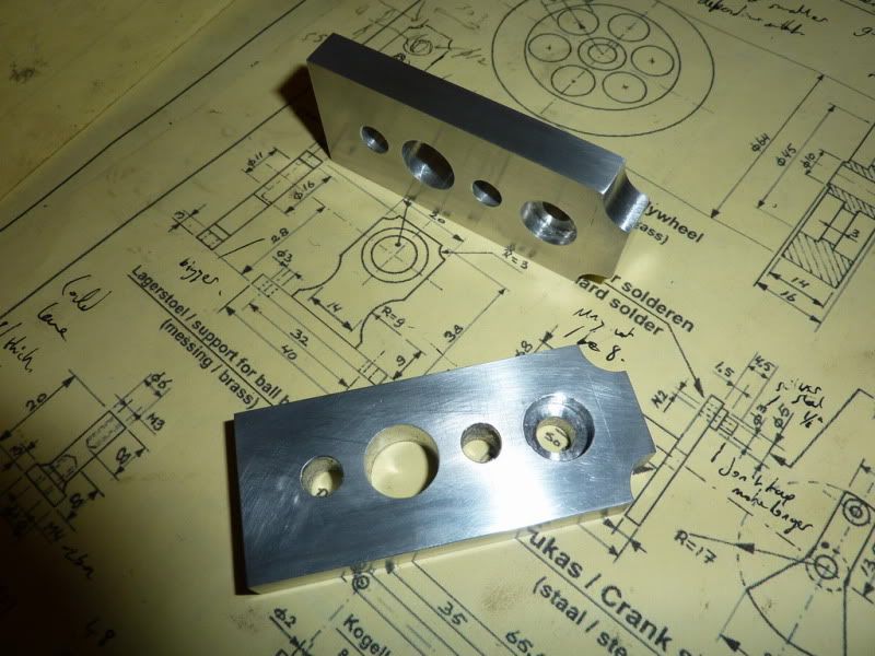
I wanted to get the bearing housings done, these were to be done from aluminum plate. Again, I am simplifying Jans design slightly. Mine will have no support pillars and are a simple rectangular shape to save time.
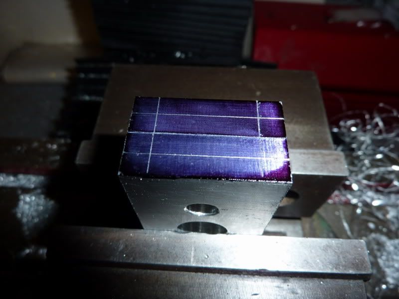
Started by marking out the outline something I have rarely done before, even used marking blue!
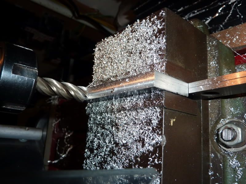
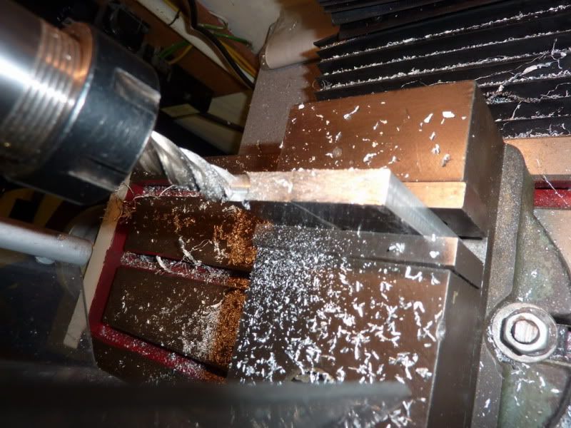
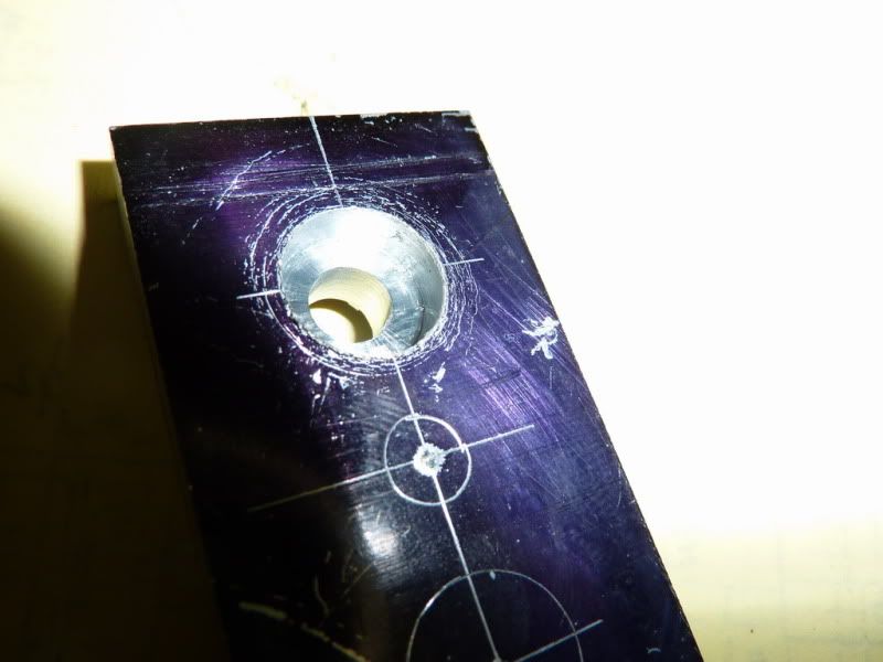
I was planning to cut the flat bottomed recess for the ball races with a 12mm end mill. But then I remembered when I tried that on the hot air engine, the hole it produced was much bigger than the bearing! That was in my old mill, with old cutters though. Nevertheless I decided to do a test run on a bit of scrap:
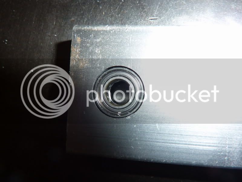
You can see that the hole produced is quite a bit too big, a very loose fit. So I set about measuring other end mills I had to see if one was just undersize there was one, but I tried that and it was no good too small!
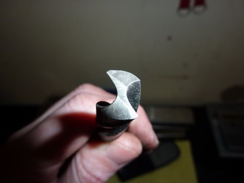
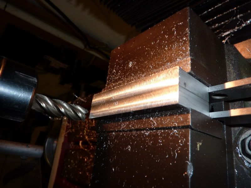
So I found a drill that was just a little undersize, 15/32 I think ~11.91mm. I ground it flat and put a couple of reliefs on it, did the test and it seemed to cut ok so I would go with this. The fit on the bearings was a press fit.
Back to the job in hand shaping the housings then:
Milling to width:
Put them together to ensure both the same width:
They ended up 0.1mm under the 30mm I decided on but it really doesnt matter! Being the same size is more critical.
Took a skim off the bottom face of both at same time are end mills meant to be used like this? It doesnt seem give the best or flattest finish.
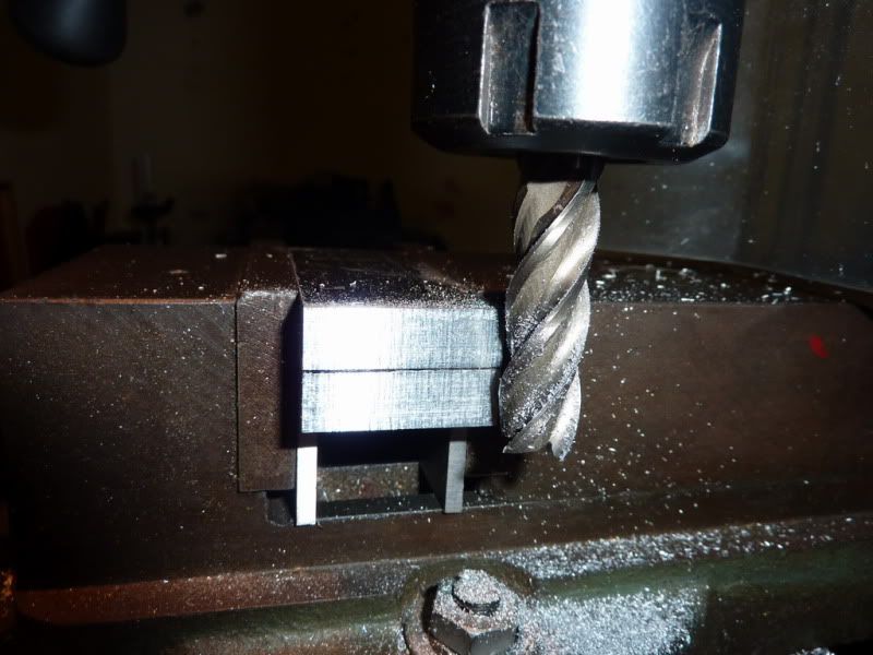
Started milling the other end to length but I didnt like using the side of the cutter like this:
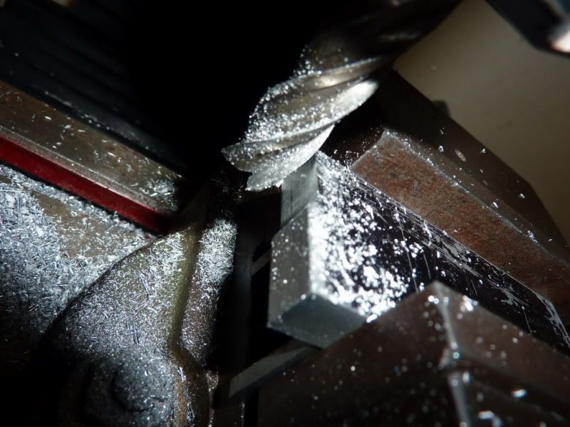
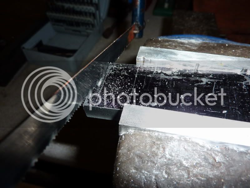
There was a few mm to take off so I sawed the excess off first:
Then milled both at once like this to ensure both the same length / height:
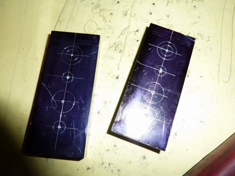
I liked this marking out lark, it was easy to see things and because the arrangement of holes Id decided on made it easy to confuse the two ends I decided to mark it out properly ish!
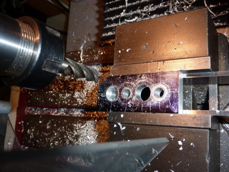
I then spend a good quarter of an hour decided what was the best procedure for drilling all the holes there were to be 2 x 6mm holes (just to make it not quite so boring), the 6.5mm hole behind the bearing to clear the 6mm crankshaft, the 12mm flat bottomed recess, and another 12mm decorative hole.
First off I decided Id just make all the holes 6.5mm to save swapping drills. Then I decided I could have drilled half the holes by now if Id just started!
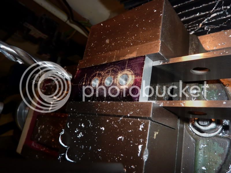
The recess looks not too bad considering its a bodged drill!
Finishing off with radiused corners I nearly always mess the part up doing this, it always seems to move in the vice. I should take little cuts instead of trying to plunge in 1 go. So I had to take another couple of finer cuts so it wont be quite to drawing but I came up with a method of getting them all the same using a parallel across the end of the vice jaws and flipping it over for the other edge. Im not even convinced it looks that good, it seems to have become one of my little trade marks! It just makes it a bit more pleasing on the eye I think?!
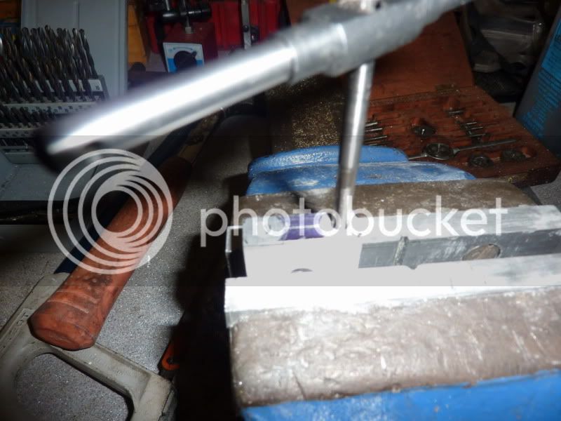
Jus the holes to drill and tap in the bottom. Im using 2ba. Again, I just marked them out and this time centre drilled then drilled.

Finishing off the tapping in the vice once the taper tap had started the thread sufficiently:
I polished them on some wet and dry to try to get some of the nasty marks out. I hate polishing though so any I do is minimal. On the 2nd one I remembered that somebody recommended using white spirit as a cutting fluid on Aluminum so I tried it for tapping. Worked pretty well, so I did a final quick polish with some white and wire wool! It was to clean them more than anything theres little point in putting actual polish on it unless all the machine marks are gone now in my opinion and they arent. I have polished all the other items on the engine just with oil and wet & dry so far, gives a nice sort of engineering brushed type finish.
So, was quite happy with those, then I pressed the bearing in with the vice, but the press fit must have been too tight and it made the bearing bind up. Luckily when I got the bearing back out it sprang back to shape and is free again but I have probably done some damage to it. So I need to open up the recesses some how so the bearings are a nice sliding or push fit. I kind of knew this, I just assumed a press fit would be ok but I guess due to the small size of these it just compressed the outer ring.
I have thought of a couple of ways of doing this. Either chuck in 4 jaw in lathe and set it running true, then make a small boring tool from an old drill and bore out marginally. The trouble will be clocking it, I dont have a dti with the little probe that flicks out sideways. Could put something good fitting in the hole and clock it that way.
Another thing I thought of was making a tiny cutter with a grub screw and bit of HSS for the milling machine.
Or, I might get away with using the 12mm end mill in the lathe once clocked in 4jaw or even just hold the cutter in the vice and twist it by hand for the amount that needs to come out. Im guessing its the run out on the cutter that makes it cut larger.
Should be able to save them some how though as the holes are too small at the mo. Any other ideas?
Nick
Got a bit more done last night, but didn't all go to plan - you'll see below! I was planning to get another bit done tonight but for some reason my 3 1/2 year old son has only just gone to bed, the wife went ages agio and left me with him! Normally he's asleep by about 19:30 and it's 22:55 now!
I wanted to get the bearing housings done, these were to be done from aluminum plate. Again, I am simplifying Jans design slightly. Mine will have no support pillars and are a simple rectangular shape to save time.
Started by marking out the outline something I have rarely done before, even used marking blue!
I was planning to cut the flat bottomed recess for the ball races with a 12mm end mill. But then I remembered when I tried that on the hot air engine, the hole it produced was much bigger than the bearing! That was in my old mill, with old cutters though. Nevertheless I decided to do a test run on a bit of scrap:
You can see that the hole produced is quite a bit too big, a very loose fit. So I set about measuring other end mills I had to see if one was just undersize there was one, but I tried that and it was no good too small!
So I found a drill that was just a little undersize, 15/32 I think ~11.91mm. I ground it flat and put a couple of reliefs on it, did the test and it seemed to cut ok so I would go with this. The fit on the bearings was a press fit.
Back to the job in hand shaping the housings then:
Milling to width:
Put them together to ensure both the same width:
They ended up 0.1mm under the 30mm I decided on but it really doesnt matter! Being the same size is more critical.
Took a skim off the bottom face of both at same time are end mills meant to be used like this? It doesnt seem give the best or flattest finish.
Started milling the other end to length but I didnt like using the side of the cutter like this:
There was a few mm to take off so I sawed the excess off first:
Then milled both at once like this to ensure both the same length / height:
I liked this marking out lark, it was easy to see things and because the arrangement of holes Id decided on made it easy to confuse the two ends I decided to mark it out properly ish!
I then spend a good quarter of an hour decided what was the best procedure for drilling all the holes there were to be 2 x 6mm holes (just to make it not quite so boring), the 6.5mm hole behind the bearing to clear the 6mm crankshaft, the 12mm flat bottomed recess, and another 12mm decorative hole.
First off I decided Id just make all the holes 6.5mm to save swapping drills. Then I decided I could have drilled half the holes by now if Id just started!
The recess looks not too bad considering its a bodged drill!
Finishing off with radiused corners I nearly always mess the part up doing this, it always seems to move in the vice. I should take little cuts instead of trying to plunge in 1 go. So I had to take another couple of finer cuts so it wont be quite to drawing but I came up with a method of getting them all the same using a parallel across the end of the vice jaws and flipping it over for the other edge. Im not even convinced it looks that good, it seems to have become one of my little trade marks! It just makes it a bit more pleasing on the eye I think?!
Jus the holes to drill and tap in the bottom. Im using 2ba. Again, I just marked them out and this time centre drilled then drilled.
Finishing off the tapping in the vice once the taper tap had started the thread sufficiently:
I polished them on some wet and dry to try to get some of the nasty marks out. I hate polishing though so any I do is minimal. On the 2nd one I remembered that somebody recommended using white spirit as a cutting fluid on Aluminum so I tried it for tapping. Worked pretty well, so I did a final quick polish with some white and wire wool! It was to clean them more than anything theres little point in putting actual polish on it unless all the machine marks are gone now in my opinion and they arent. I have polished all the other items on the engine just with oil and wet & dry so far, gives a nice sort of engineering brushed type finish.
So, was quite happy with those, then I pressed the bearing in with the vice, but the press fit must have been too tight and it made the bearing bind up. Luckily when I got the bearing back out it sprang back to shape and is free again but I have probably done some damage to it. So I need to open up the recesses some how so the bearings are a nice sliding or push fit. I kind of knew this, I just assumed a press fit would be ok but I guess due to the small size of these it just compressed the outer ring.
I have thought of a couple of ways of doing this. Either chuck in 4 jaw in lathe and set it running true, then make a small boring tool from an old drill and bore out marginally. The trouble will be clocking it, I dont have a dti with the little probe that flicks out sideways. Could put something good fitting in the hole and clock it that way.
Another thing I thought of was making a tiny cutter with a grub screw and bit of HSS for the milling machine.
Or, I might get away with using the 12mm end mill in the lathe once clocked in 4jaw or even just hold the cutter in the vice and twist it by hand for the amount that needs to come out. Im guessing its the run out on the cutter that makes it cut larger.
Should be able to save them some how though as the holes are too small at the mo. Any other ideas?
Nick
mklotz
Well-Known Member
Nick,
Re the raw edge you're getting when you use the side of the endmill to trim a piece...
After making the cut (in the conventional direction) that brings the piece to size, reverse your feed and, without putting any more cut on, make a climb cut over the piece. (Since you've not put any cut on, there's no chance of the mill grabbing.) The improvement in finish will astound you, especially so if your mill has power feed.
Nick, I think for boring out the bearing recess, I would make a gauge pin to fit the smaller hole, then use a regular DI to dial it in with the four jaw. Then just bore it for a tight slide in fit, and use an adhesive to hold the bearing firm.
If you have a boring head, you could do something similar with the milling machine. Make a gauge pin for the smaller hole that will fit in a mill collet on one end, and use that to locate the center of the small hole by positioning the mill tables. You'll probably have to make a small cutter with the proper shank size for the boring head to fit in the bearing recess.
You might try a sanding dowel. A piece of wood dowel a bit under sized, say 3" long. Drill a hole for a small wood screw in one end, and then split that end for a couple of inches down the center line. Glue fine wet or dry to the circumference and then split it same as the dowel is split. Use the wood screw in the end to expand the dowel. It works kind of like a lap, but will cut pretty fast, so go easy.
For the finish with the end mill, yes it is made to cut on the side, (the flutes), if they are made the same as we have in the U.S. You can do like Marv says to get a better cut. If you have a two flute cutter, it will make a better finish yet on aluminum. Run it fast for your final "no cut" pass.
It's looking good, by the way! I'm sure you'll get it fixed up for the bearings.
Dean
Thanks for the tips Marv and Dean. I thought climb milling gave a better finish but got put off after I nearly mangled the cylinder! But it'll be ok with no cut on so it's just touching the work. Will have a think about which way to go. think I will try the sanding dowel then if that's no good set up in 4 jaw and bore.
Thanks
Nick
Thanks
Nick
Similar threads
- Replies
- 13
- Views
- 763