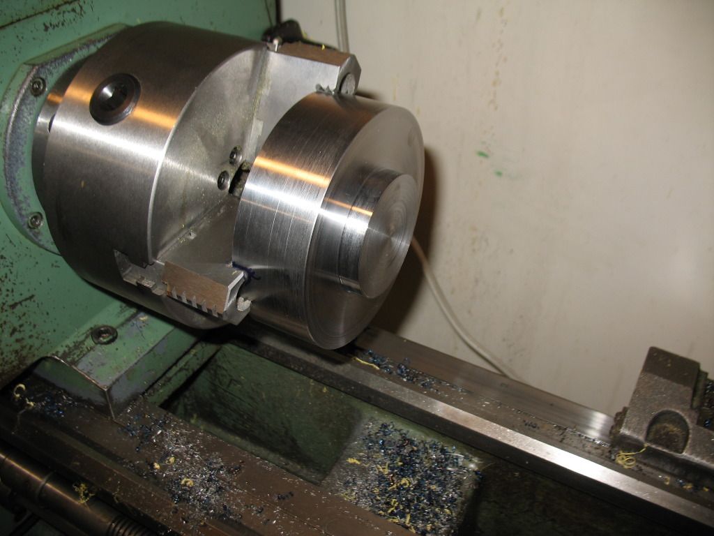
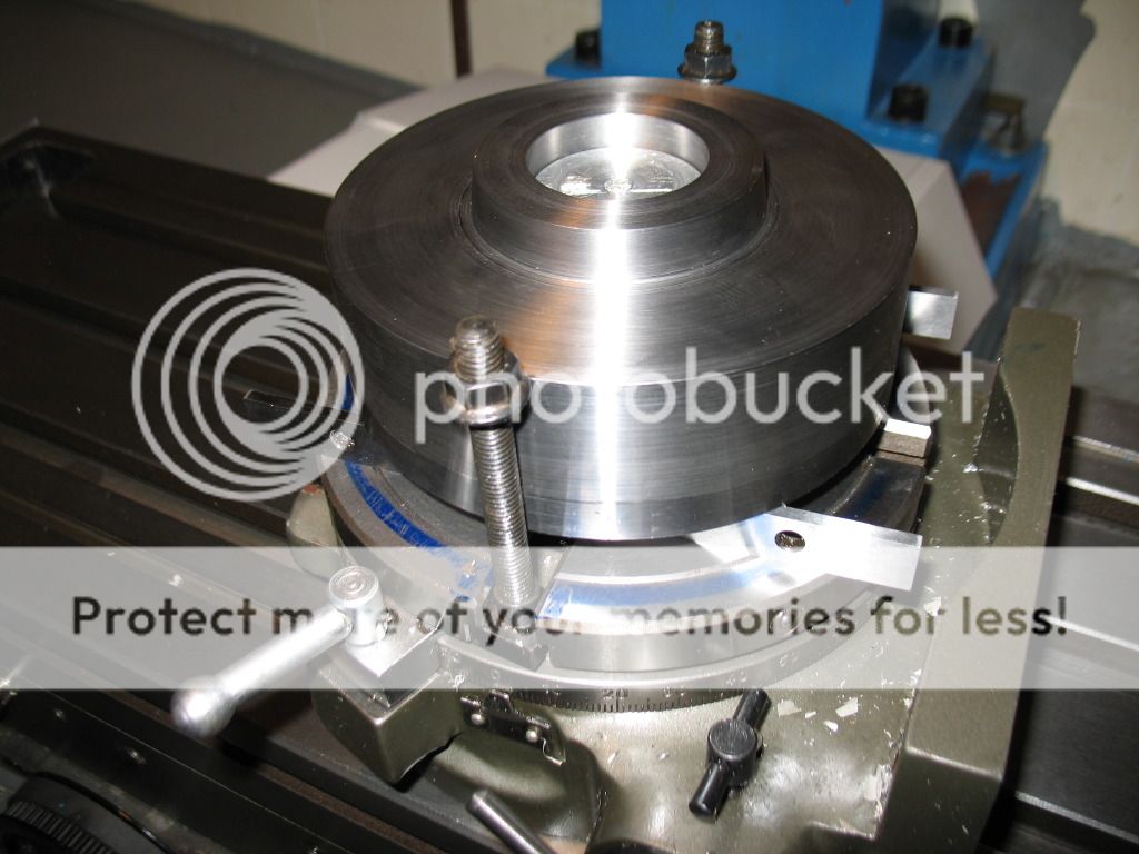
Making a D1 4 Chuck reciever for a rotary table.

Home Model Engine Machinist Forum

Help Support Home Model Engine Machinist Forum:

This site may earn a commission from merchant affiliate links, including eBay, Amazon, and others.
Graeme,

I myself never heard back from deere_x475guy, so I ventured to make my own. I can send to you a Pro/e cad file and or 3d PDF of the one I made if you'd like? You can take dimensions from either.

Let me know.

Mike
 
Ninefinger,
Thanks, I still haven't heard back from this guy so anything you can send would be appreciated
 
Hi Ninefinger,

If you don't mind, could I get a copy of the PDF too?

Thanks!
 
Actually, Bob disappeared a few years ago from this and all other sites.
The last time I spoke to him on Skype, he was going into production for himself, charging well over $400 for the finished article. Whether he ever got it up and running I have no idea, but I have seen some, a few years back being sold on the Bay.
I wouldn't think there was much call for them as they are so bulky and also expensive to make, much cheaper to do what I did, I made an adapter to convert my D1-4 nose to Myford thread and use cheaper smaller chucks.
So that the chucks could be swapped from lathe to RT (which also has a Myford thread nose) and vice versa with the job still being held in the chuck. It takes only a couple of minutes to convert the lathe back to D1-4.

John
 
I have a D1-3 adapter that I made from the spindle of a parted-out lathe. I have mostly mounted it in mill vise vs. rotab.
 
I have put into the downloads area some files for the D1-4 adapter. I hope that will help a few people out. I have not included a proper drawing yet as I'm in the process of learning Autodesk Fusion 360 and I haven't got there yet! Hopefully with the included files most people will be able to work out the required dimensions. One day I will get around to creating the drawing for this and I'll add it. I might do it as part of my exercises in learning Fusion 360....
**Edit - I thru together a rough drawing with most required dimensions and added it***
As to why I choose to go this route? My lathe uses the D1-4 chucks and I have 3 of them. All I wanted was a way to take the chuck from the lathe to the mill. Seemed like the best way to do it - 1 extra part that will stay bolted to my rotary table for extended periods. My mill is CNC and I'll eventually add cnc to the rotary table and I will be able to do 3 + 1 milling (I can do that now too, just program in a pause so I can rotate the part manually). Expensive to make? If I recall it was a $35 Canadian piece of steel and my time which although not free was time well spent.

As for bulk - I intend to use it mostly with the axis parallel to the X-axis on my mill. I'm also not too concerned with Z space on my mill as it has ~18" which is plenty even when all the pieces are stacked up if I do use it pointing up.

Mike
 
Last edited:
Not being critical but just a comment.In an early photo you showed a hex collet
block being gripped in the mill vice with flat to bottom and jaws gripping
the corners.I would use it the other way,gripping the flats and locating the corner on the bottom of the vice.Which is the correct/preferred way
Regards Barry
 
Old thread I hope still works. I too would like to see your version of the plan. New to the forum, new to machining but now finally tooled up. Full size Bridgeport clone, vertical shaper, 1340 lathe, and a 4 x 6 bandsaw ready to slice that 57 lb slug down to size. A great starter project for the 10 inch rotary table. Thanks either way.
 
While there are few limited situations that swinging the chuck from lathe to mill makes good sense. Overall I consider it a poor use of time to make a D-1 adapter. A 4" 3 jaw and a larger 4 jaw mounted to an RT make much more sense in terms of usefulness. IMHO

A milling machine with a good DRO has a bolt circle program built in, and much quicker to use that an RT. As well as tangent functions, Arc segments on a mill are doable, but need handwork to be finished, an RT would not need handwork to finish, but setup calculations are often lenghty, and cutting arc's is not that easy in either case.
 
I have a single axis cnc adapted stepper motor attached to my 10 inch RT. I plan to use this in my conversion to a 4 axis cnc platform. The mill will be able to out perform my lathe at the task I am working toward. So yes I want a d1-4 adapter, just wanted numbers not opinion.
 
Ninefinger,
This is a very cool project , one I would like to make. I am going to mount a chuck to my bridgeport today to make a spanner socket (think little fingers) and it is kinda thin ( mill vise will crush)
any drawings or build notes or drawings would be greatly appreciated.

Happy Hunting
archie
 
Hi everyone,
Sorry to be qite à lurker but it's never easy to commit in a community when you have another one in your native language ;)

I would be very interested in the drawing also, any chance to get it?

Thank you
 
Ninefinger:

I'd appreciate it if you would save the Fusion 360 cad files to the DWG format. Then those of us that use other cad programs can open them.

Ken Olsen
 
Well, I bit the bullet and ordered the ASME spec for spindle noses for $35.
The spec can be ordered here: http://www.asme.org/products/codes---standards/spindle-noses-for-tool-room-lathes--engine-lathes- This spec has a drawing in it that is essentially all you need to make this part, except for the 4 through holes to attach to a rotary table. I was stuck at trying to reverse engineer the spindle on my lathe and get some of the angles / dimensions and I just gave up - $35 bucks and now I have all the dimensions I could ever want for the cam locks, pins, etc for all the spindle sizes.

I used 5" diameter hot rolled 1018 steel. It cut beautifully on the lathe (bright blue chips) but in retrospect I should have chosen something that could be nitride hardened (1018 isn't suitable for nitriding). I'll probably just use it unhardened and be very careful with it and / or touch it up if it ever gets messed up. I made it once I can make it again!

D1-4-adapter001.jpg


Here is a picture of where I am at now. Unfortunately I am stalled out as my mill is down for repair (long story there). I will post my completed unit when I am done.
I know the hold downs are not suitable. They are just temporary / lightly holding it until I find a suitable bar in scrap pile to hold down across the top, and I didn't want the parallels coming out. They are there cause obviously I wanted a space underneath for the drill to break through so I don't ruin my rotary table in the process.

D1-4-adapter004.jpg


Regards,

Mike
Hi,
Are those dimensions / specs available in Machinery's Handbook ?
 
Hi,
Are those dimensions / specs available in Machinery's Handbook ?
No - the spindle dimensions for the D1-4 style are only listed in the ASME spec which is copyright protected - you can find some of the details on-line but I eventually gave up and bought the spec.
 
Ninefinger,
This is a very cool project , one I would like to make. I am going to mount a chuck to my bridgeport today to make a spanner socket (think little fingers) and it is kinda thin ( mill vise will crush)
any drawings or build notes or drawings would be greatly appreciated.

Happy Hunting
archie

There are drawings in the Downloads section. Looks like its on the 2nd page now, and the link I posted previously doesn't bring me there anymore, but a quick search should let you find it. The pdf's should have all the needed info to build your own. As mentioned in this thread I'd make it a slightly larger diameter if I were to do it again.
 
Ninefinger:

I'd appreciate it if you would save the Fusion 360 cad files to the DWG format. Then those of us that use other cad programs can open them.

Ken Olsen
Ken, attached is a DWG of the drawing - I can't export a DWG of the model itself. Also attached is the pdf for convenience of those looking for it.
 

Attachments

  • adapter-assembly Drawing v9.dwg
    243.6 KB
  • adapter-assembly Drawing v9.pdf
    130.7 KB
Back
Top