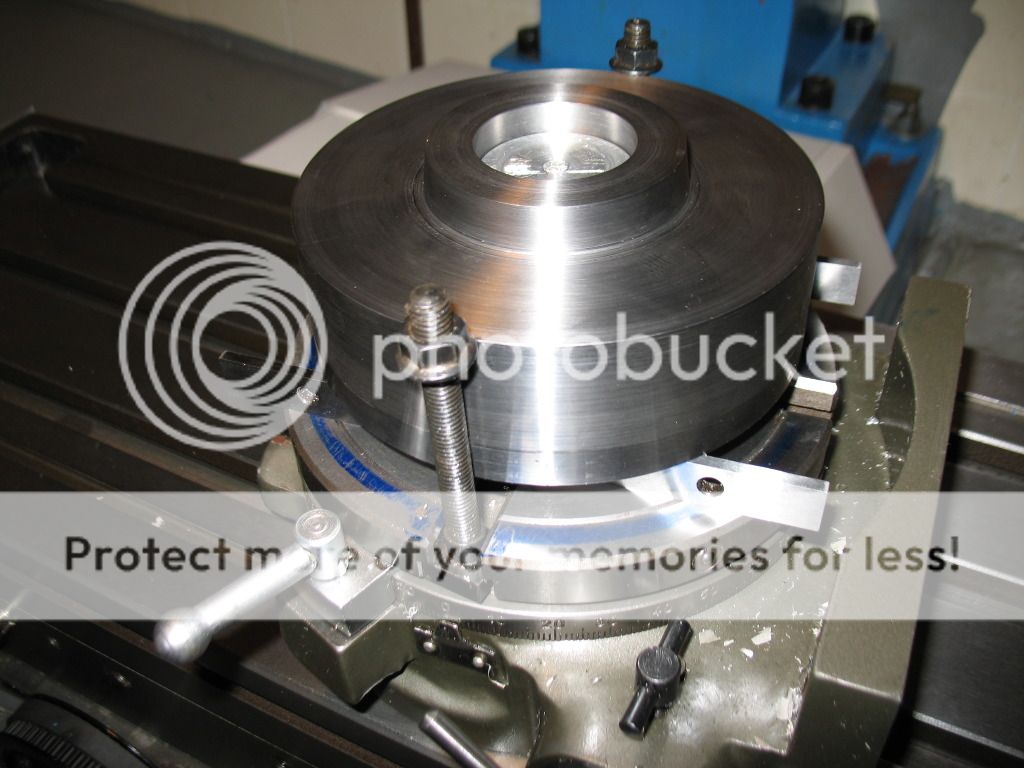
Making a D1 4 Chuck reciever for a rotary table.

Home Model Engine Machinist Forum

Help Support Home Model Engine Machinist Forum:

This site may earn a commission from merchant affiliate links, including eBay, Amazon, and others.
Thanks Owen,
I didn't specify anything because I figured each person would have their own size protruding round thingy that would be sticking out of the rotary table....just locate center on the back side then drill/ream to size of your round thingy. ;D
 
For those of you wanting the plans in metric...have patience...I have let Alibre convert them but I have a friend in the UK that is going to go over them to make sure the dimensions make sense...ETA is probably this weekend.
 
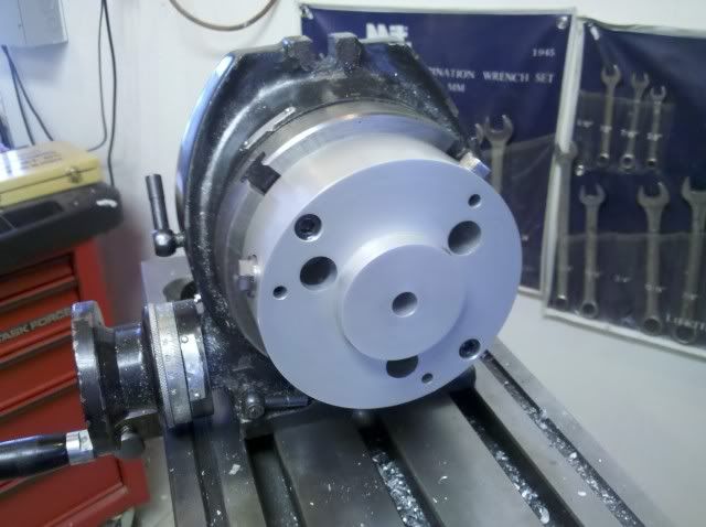
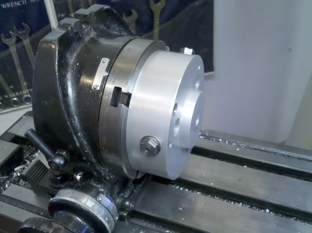
I know this is an old post but I thought I would show what this part would look like after being in continual use for the last year and a half. Weston Bye anodized this for me in August of 2009 and this is what it looks like today. Surprising what protection a good anodizing will give.


IMG_20110108_092215.jpg


IMG_20110108_092231.jpg


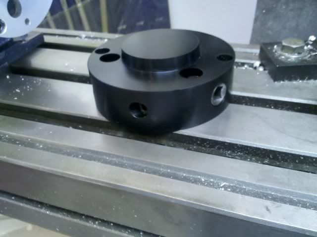
This was the first version and below is what I have just finished. This one takes the OEM camlock pins that can be ordered from various suppliers when the campin wears.

IMG_20110108_094223.jpg
 
Hi Bob,
I'm a newbie here and just opened the tooling area and read you're post.
What A fantastic post, I have a Emco Super 11 with D1 4 Chuck fitting, and it has always frustrated me that I had to remove a job from the chuck to place under the milling machine.
When the receiver was Anodised did you loose any accuracy as I understand the process etches into the metal.
Could I trouble you for a copy of the plans in metric please.
I will now open all other posts to look for inspiration.
Once again great post.
Kindest Regards
Dave Weir......(Beagles)
[email protected]

 
Hi Deere
I have just come in from the shed /shop and saw your great post
I love it
I must have it
please send me a set of plans too
my lathe is both metric and imp but I seem to work mainly in imp
I dont know how I missed such a great post
but seeing your pics of your face plate and 4 jaw on the mill got me excited !!
I already half way into a project now but I want this!!
Thanks Pete
 
Metalmad,
Thanks for the encouraging words. I sent you the metric but just read your post so I will also send you the Imp version.
 
Lockstocknbarrel said:
Hi Bob,
I'm a newbie here and just opened the tooling area and read you're post.
What A fantastic post, I have a Emco Super 11 with D1 4 Chuck fitting, and it has always frustrated me that I had to remove a job from the chuck to place under the milling machine.
When the receiver was Anodised did you loose any accuracy as I understand the process etches into the metal.
Could I trouble you for a copy of the plans in metric please.
I will now open all other posts to look for inspiration.
Once again great post.
Kindest Regards
Dave Weir......(Beagles)
[email protected]

Dave, I just sent out both the metric and the imperial version to you. No change on the fit up with the anodizing. I check each one I have built (5 now) and the runout has always been exactly the same as I would see on the lathe. I test with parts in my set through 5C Collet chuck and my Bison 3 jaw with softjaws. The process when done correctly will add about half the thickness of the layer to are shooting for. I usually try for .0007.
 
Hi Bob
Very well done!!! I love it and I would like to have it , please send me a set of plans too..!
:bow: Thanks in advance..
Paolo
 
Paolo,
Both sets are on the way. Like I said I haven't machined the metric version yet so let me know if you see any problems with them. I will correct them and re-send them to everyone.

Good Luck..

 
Hi Bob,
Thanks for the plans very professional.
Where do you source the factory female pins...?
What Part Number...?
And at what cost...?

Why have you made 5 of these Receivers................ ???
Kindest Regards
Dave.............Beagles
[email protected]
 
Dave, it appears I need to edit my post with the pictures. The drawings I have given out are for the first version. That version does not take the OEM camlocks. You should have drawings included for the non OEM pins. If they didn't come through with the PDF let me know and I will send it again. Also if you need help in making the pins let me know and I will help you through the process.

The black one in the picture is my second version and it uses the OEM pins. This one I am selling on eBay.

http://cgi.ebay.com/ws/eBayISAPI.dll?ViewItem&item=220732913092&ssPageName=STRK:MESELX:IT

I will also sell directly to anyone on the forums if someone wants one.
 
deere_x275guy, that's is the best idea i have seen in a while. Sure beats having to dedicate a chuck to your rotary table. could you send me, a set of plans? Regards Mike
 
Excellent project - I've found it almost impossible to obtain commercial products for the D1 4 chucks (without price tags that are simply beyond my means!)

Please could you send me a copy of the plans too.

Many thanks,

Nick
 
Hi Everybody,
It has taken me some time to post again since asking Bob for a copy of the plans, since then Bob has sent me a complete "D1 4 Chuck Receiver".
I had a urgent job to complete and the time to make and stall all other work in the shop, it just made sense to me to bite the bullet and buy a made up unit.
Yes I know why buy when you could make the part but sometimes I just give the Dog another chocolate biscuit and move on.
Bob was so professional in all dealings and freighting around the other side of the plant was not a problem, there are many machine suppliers that could take a lesson or two from this man's service to a customer.
Thanks Again Bob.

Kindest Regards
Beagles.
 
Hi DeerGuy,
I hope this thread hasn't gone dead. I'd love to get a set of the plans for the D1-4 reciever. That will be so much better than taking mine apart to dope out a set of plans.
I've got a fairly new 14-40 lathe that I've converted to CNC. I plan to make D1-4 ER 40, ER 25, c-5, closers and it will be great to be able to move these to My 8" rotary.
[email protected]
Be glad to Paypal any charge.
Thanks in advance
Ozzie
 
Last edited:
Hi DeerGuy,
I hope this thread hasn't gone dead. I'd love to get a set of the plans for the D1-4 reciever. That will be so much better than taking mine apart to dope out a set of plans.

This is funny because I was thinking the exact same thing right now...I was googling around looking for a D1-4 receiver and it came back here to one of my favorite forums!

Bob (DeerGuy), yes please let me know if you're still offering up the drawings for this adapter. Its on the to do list now that I made my carriage stop for my lathe. Going from the lathe to the mill would be so nice if I can keep the part in the chuck.

Regards,

Mike
 
Hi Bob,
Relatively new here, just came across this post and was blown away as this type of attachment has been on my to do list for a while, so would be interested in a set of plans if still available.
Regards
Terry
 
Well, I bit the bullet and ordered the ASME spec for spindle noses for $35.
The spec can be ordered here: http://www.asme.org/products/codes---standards/spindle-noses-for-tool-room-lathes--engine-lathes- This spec has a drawing in it that is essentially all you need to make this part, except for the 4 through holes to attach to a rotary table. I was stuck at trying to reverse engineer the spindle on my lathe and get some of the angles / dimensions and I just gave up - $35 bucks and now I have all the dimensions I could ever want for the cam locks, pins, etc for all the spindle sizes.

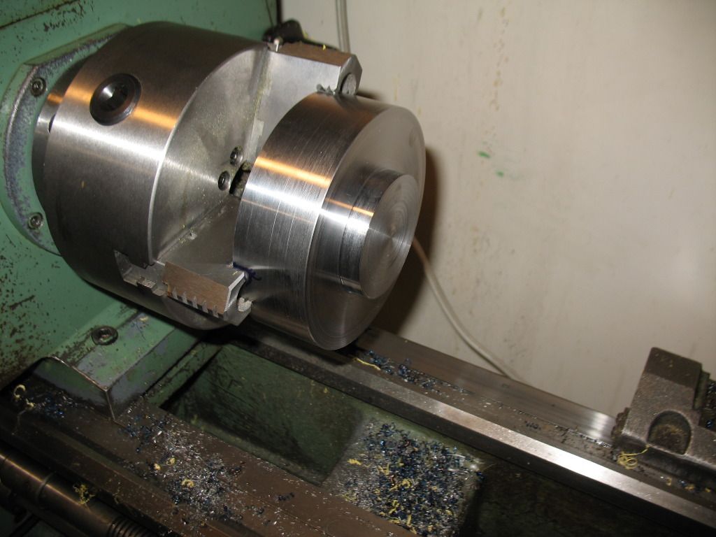
I used 5" diameter hot rolled 1018 steel. It cut beautifully on the lathe (bright blue chips) but in retrospect I should have chosen something that could be nitride hardened (1018 isn't suitable for nitriding). I'll probably just use it unhardened and be very careful with it and / or touch it up if it ever gets messed up. I made it once I can make it again!

D1-4-adapter001.jpg


Here is a picture of where I am at now. Unfortunately I am stalled out as my mill is down for repair (long story there). I will post my completed unit when I am done.
I know the hold downs are not suitable. They are just temporary / lightly holding it until I find a suitable bar in scrap pile to hold down across the top, and I didn't want the parallels coming out. They are there cause obviously I wanted a space underneath for the drill to break through so I don't ruin my rotary table in the process.

D1-4-adapter004.jpg


Regards,

Mike
 
Hi, deere_x475guy,
Are the plans still available for the receiver? if so could you send both metric and imperial.

many thanks

Graeme
 
Back
Top