
You are using an out of date browser. It may not display this or other websites correctly.
You should upgrade or use an alternative browser.
You should upgrade or use an alternative browser.
Lobo Pup Twin 1.6 cc diesel
- Thread starter GailInNM
- Start date


Help Support Home Model Engine Machinist Forum:
This site may earn a commission from merchant affiliate
links, including eBay, Amazon, and others.
- Joined
- Feb 17, 2008
- Messages
- 2,330
- Reaction score
- 445
Thanks everyone. It starts to get exciting when the end of a build is in sight.
Zee: I used 6061 aluminum, but any kind will work. I would avoid the hardware store variety however as it is too soft to cut well. I keep abrasive paper in small 2 x 4 inch pieces near the lathe. It is stepped in grades of 400,600,800,1000 and 1200 grit. On the venturi I rounded the edge with 600 grit and then touched everything with 800 and 1200 grit while running the lathe at about 2000 RPM. Finally, I have a small piece of heavy duty paper towel about the same size that had some Mothers metal polish on it at one time. I used the blackened end of it where the polish was for maybe 15 seconds and then used the clean end for a few seconds. So, it's not really polished up. Just enough work done to make it presentable. Less than 2 minutes all told.
Since Dean jumped in and covered the compound setting vs included angle (Thanks Dean!) I don't have to cover that. One small item on it however. My lathe has the zero degree setting when the compound is operating parallel to the lathe bed. Some lathes have the zero when the compound is in the axis of travel is the same as the cross slide. On them the setting would be 90 degrees minus the 12 degree setting, or 78 degrees.
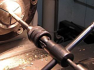
Two of the parts left are the nuts to lock the venturi to the crankcase and the nut for the spraybar mounting. They are easy, and the operations are the same for both so I will just roll them into one post. Although I used hex stock for these, they could just a well be made of round stock with a flat milled on two opposing sides. I normally make up a few extra as it is very little extra work.
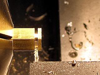
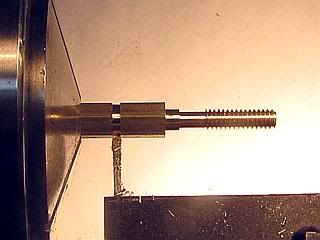
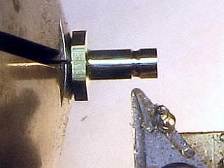
Starting off, the stock is faced off, center drilled and drilled with a tap drill. Then tapped. If making extras, the tap can be run in deep enough for all of them. Then part off the individual nuts using a narrow parting tool. The one I am using in the photo is ground to 0.018 wide.
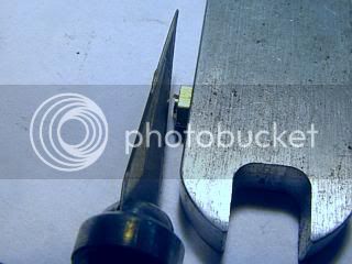
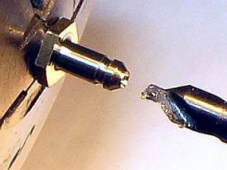
The nuts will have a nasty burr on the cutoff side. There is no way to avoid this as the final part of the cut is going into the internal thread which will catch to tool at the final stage. I use a hobby knife to slice off most of this burr. On small nuts, like these, it is helpful to stand it upright against a scrap of metal rather than try to hold it with your fingers. Easier on fingers also.
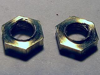
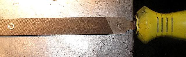
Fnally I clean up the remaining burrs on both sides of the nut by sliding the nut along a fine file. I set the file on a flat surface and hang the handle over the edge. Slide the nut toward the handle while putting light downward pressure on the nut with your finger tip. On the side that had the nasty burr it will probably take two strokes and only one on the other side. I am using a 6 inch single cut mill bastard file in the photo.
Gail in NM
Zee: I used 6061 aluminum, but any kind will work. I would avoid the hardware store variety however as it is too soft to cut well. I keep abrasive paper in small 2 x 4 inch pieces near the lathe. It is stepped in grades of 400,600,800,1000 and 1200 grit. On the venturi I rounded the edge with 600 grit and then touched everything with 800 and 1200 grit while running the lathe at about 2000 RPM. Finally, I have a small piece of heavy duty paper towel about the same size that had some Mothers metal polish on it at one time. I used the blackened end of it where the polish was for maybe 15 seconds and then used the clean end for a few seconds. So, it's not really polished up. Just enough work done to make it presentable. Less than 2 minutes all told.
Since Dean jumped in and covered the compound setting vs included angle (Thanks Dean!) I don't have to cover that. One small item on it however. My lathe has the zero degree setting when the compound is operating parallel to the lathe bed. Some lathes have the zero when the compound is in the axis of travel is the same as the cross slide. On them the setting would be 90 degrees minus the 12 degree setting, or 78 degrees.
Two of the parts left are the nuts to lock the venturi to the crankcase and the nut for the spraybar mounting. They are easy, and the operations are the same for both so I will just roll them into one post. Although I used hex stock for these, they could just a well be made of round stock with a flat milled on two opposing sides. I normally make up a few extra as it is very little extra work.
Starting off, the stock is faced off, center drilled and drilled with a tap drill. Then tapped. If making extras, the tap can be run in deep enough for all of them. Then part off the individual nuts using a narrow parting tool. The one I am using in the photo is ground to 0.018 wide.
The nuts will have a nasty burr on the cutoff side. There is no way to avoid this as the final part of the cut is going into the internal thread which will catch to tool at the final stage. I use a hobby knife to slice off most of this burr. On small nuts, like these, it is helpful to stand it upright against a scrap of metal rather than try to hold it with your fingers. Easier on fingers also.
Fnally I clean up the remaining burrs on both sides of the nut by sliding the nut along a fine file. I set the file on a flat surface and hang the handle over the edge. Slide the nut toward the handle while putting light downward pressure on the nut with your finger tip. On the side that had the nasty burr it will probably take two strokes and only one on the other side. I am using a 6 inch single cut mill bastard file in the photo.
Gail in NM
zeeprogrammer
Well-Known Member
- Joined
- Mar 14, 2009
- Messages
- 3,362
- Reaction score
- 13
Thanks Gail. Great information. Including how many strokes to clean up the nuts. It's that kind of detail that helps people like me out. Also the amount of time spent. Gives people some idea of what's involved and how much is required.
Gail,
Thanks for the write up. I would probably have tried something crazy like put the nuts back in the lathe and it all gone horribly wrong! When all it needs is 3 strokes on the file what is the point! it's little tips like this that can save a lot of time etc.
Nick
Thanks for the write up. I would probably have tried something crazy like put the nuts back in the lathe and it all gone horribly wrong! When all it needs is 3 strokes on the file what is the point! it's little tips like this that can save a lot of time etc.
Nick
- Joined
- Feb 17, 2008
- Messages
- 2,330
- Reaction score
- 445
Thanks Zee & Nick.
Key to filing the nuts is getting most of the burr off with the hobby knife. If you don't do this the burr will catch in the grooves of the file and all you do is wear out your finger tip.
Nick: Putting the nuts back in the lathe is not crazy. I did 10 of the 5-40 nuts, so I would have some for stock, and that is about the limit as to what my finger tip can take. If I were making more I would have put a 5-40 bolt in a split collet in the lathe and put the nut on it. Then I would have used a facing tool to remove the excess threads from the screw and cut the burr off. After the first one the reduced thread section is used to get the nut started.
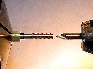
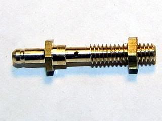
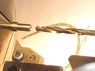
The last complicated part is the spraybar. It is not really complicated, but it does have a lot of operations on a small part. Three of the operations are a little bit difficult, but fortunately dimensions are not critical. They are the drilling of the hole lengthwise through the spraybar with two different size drills and drilling the cross hole through one side of the spraybar.
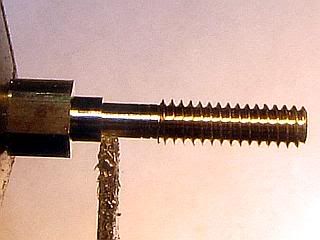
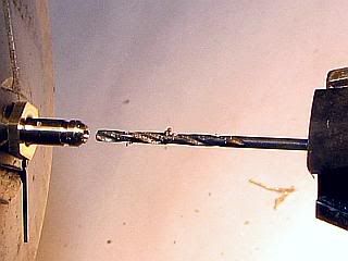
Starting off with 3/16 hex bar stock, it was turned to 0.125 diameter for 0.625 length, and then threaded for about 7/16 of an inch with a 5-40 die. Thats 16 to 18 turns of the die.
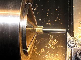
The section that will be centered up in the venturi is reduced to 0.093 inch using a square nose parting tool. I used a 0.040 tool. Too wide a tool will probably grab and bend the part. Then the part is center drilled and drilled to a depth of 5/8 inch with a 0.063 drill. After the first 0.2 inch or so it was necessary to peck drill in about 0.05 increments to keep the flutes of the drill bit from filling up. Then the part was extended from the collet some additional length and parted off a little bit long to allow cleanup of the end.
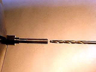
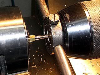
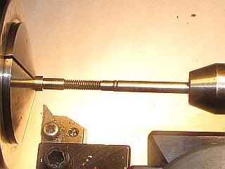
After changing collets in the lathe, the other end of the part was cleaned up to length and turned down to 0.093. A shallow groove was put in to help retain the fuel line and the end was beveled a little bit with a file to make it easier to get the fuel line on.
The final lathe work is to center drill and drill with a 0.040 drill through to meet the hole from the other end.
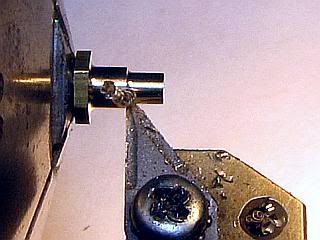
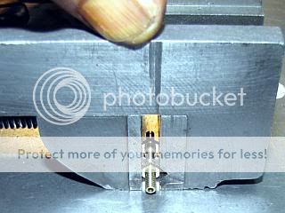
A nut was put on the spraybar and then the spraybar was lightly gripped in a small drill press vice with the hex portion of the nut and spraybar slightly above the top of the vice. Turning the vice over, it was pressed down on a hard surface to bring the points on the hex level with the top of the vice and the vice tightened. A parallel could have been used under the spraybar, but this method is a quick way to get the spraybar level in the vice.
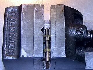
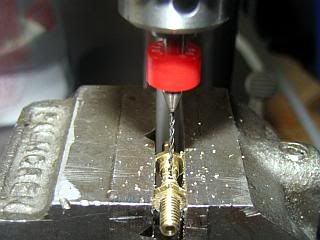
Finally, the cross hole through one side of the spray bar needs to be drilled. Fortunately, the exact position is not critical and neither is the size. The size should be some where around 0.032 diameter, but anything under 0.040 down to about 0.025 should work well. I used a #68 drill because I have a small pile of carbide circuit board drills that size. I put the vice on the drill press table at about a 45 degree angle so by moving my head left and right I could look either length wise of the spraybar or perpendicular to it. I centered the drill on the width of the spray bar and in the center of the reduced diameter section by eye and drilled through one side of the spraybar. I was using a 5 power visor for this. Some people wish for 20 year old eyes. I would settle for 60 year old eyes. So if I can do it most anyone can. Any way, the position if the hole is really not very critical so if it looks about right it will work.
Finally, using the 0.063 drill, I deburred the inside of the spraybar to remove the burrs left by drilling from the other end and from the cross drilling. I held the drill bit in my fingers, and first turned the drill backwards to break off the burrs and then forward. If you turn forward at first, the drill will try to pull into the hole at the far end when it first engages the burr. Clean out the spraybar with compressed air or blow through it. Any crud in it can really make getting a smooth needle valve setting very difficult.
Gail in NM
Key to filing the nuts is getting most of the burr off with the hobby knife. If you don't do this the burr will catch in the grooves of the file and all you do is wear out your finger tip.
Nick: Putting the nuts back in the lathe is not crazy. I did 10 of the 5-40 nuts, so I would have some for stock, and that is about the limit as to what my finger tip can take. If I were making more I would have put a 5-40 bolt in a split collet in the lathe and put the nut on it. Then I would have used a facing tool to remove the excess threads from the screw and cut the burr off. After the first one the reduced thread section is used to get the nut started.
The last complicated part is the spraybar. It is not really complicated, but it does have a lot of operations on a small part. Three of the operations are a little bit difficult, but fortunately dimensions are not critical. They are the drilling of the hole lengthwise through the spraybar with two different size drills and drilling the cross hole through one side of the spraybar.
Starting off with 3/16 hex bar stock, it was turned to 0.125 diameter for 0.625 length, and then threaded for about 7/16 of an inch with a 5-40 die. Thats 16 to 18 turns of the die.
The section that will be centered up in the venturi is reduced to 0.093 inch using a square nose parting tool. I used a 0.040 tool. Too wide a tool will probably grab and bend the part. Then the part is center drilled and drilled to a depth of 5/8 inch with a 0.063 drill. After the first 0.2 inch or so it was necessary to peck drill in about 0.05 increments to keep the flutes of the drill bit from filling up. Then the part was extended from the collet some additional length and parted off a little bit long to allow cleanup of the end.
After changing collets in the lathe, the other end of the part was cleaned up to length and turned down to 0.093. A shallow groove was put in to help retain the fuel line and the end was beveled a little bit with a file to make it easier to get the fuel line on.
The final lathe work is to center drill and drill with a 0.040 drill through to meet the hole from the other end.
A nut was put on the spraybar and then the spraybar was lightly gripped in a small drill press vice with the hex portion of the nut and spraybar slightly above the top of the vice. Turning the vice over, it was pressed down on a hard surface to bring the points on the hex level with the top of the vice and the vice tightened. A parallel could have been used under the spraybar, but this method is a quick way to get the spraybar level in the vice.
Finally, the cross hole through one side of the spray bar needs to be drilled. Fortunately, the exact position is not critical and neither is the size. The size should be some where around 0.032 diameter, but anything under 0.040 down to about 0.025 should work well. I used a #68 drill because I have a small pile of carbide circuit board drills that size. I put the vice on the drill press table at about a 45 degree angle so by moving my head left and right I could look either length wise of the spraybar or perpendicular to it. I centered the drill on the width of the spray bar and in the center of the reduced diameter section by eye and drilled through one side of the spraybar. I was using a 5 power visor for this. Some people wish for 20 year old eyes. I would settle for 60 year old eyes. So if I can do it most anyone can. Any way, the position if the hole is really not very critical so if it looks about right it will work.
Finally, using the 0.063 drill, I deburred the inside of the spraybar to remove the burrs left by drilling from the other end and from the cross drilling. I held the drill bit in my fingers, and first turned the drill backwards to break off the burrs and then forward. If you turn forward at first, the drill will try to pull into the hole at the far end when it first engages the burr. Clean out the spraybar with compressed air or blow through it. Any crud in it can really make getting a smooth needle valve setting very difficult.
Gail in NM
Nice work Gail, that looks a pretty small part. I've just been doing some fiddley bits and I actually put a 6ba bolt in the lathe and faced the end off to shorten it, and the bolt face as it was galvanised so wanted to get rid of that. Not that crazy afterall, it worked!
Nick
Nick


$519.19
$699.00
FoxAlien Masuter Pro CNC Router Machine, Upgraded 3-Axis Engraving All-Metal Milling Machine for Wood Acrylic MDF Nylon Carving Cutting
FoxAlien Official

$94.99
$109.99
AHS Woodmaster 4400 Maintenance Kit for Outdoor Wood Boiler Treatment
Alternative Heating & Supplies


$40.02
$49.99
Becker CAD 12 3D - professional CAD software for 2D + 3D design and modelling - for 3 PCs - 100% compatible with AutoCAD
momox Shop


$99.99
AHS Outdoor Wood Boiler Yearly Maintenance Kit with Water Treatment - ProTech 300 & Test Kit
Alternative Heating & Supplies

$12.56
$39.95
Complete Plans for Building Horse Barns Big and Small(3rd Edition)
ThriftBooks-Atlanta

$39.99
$49.99
Sunnytech Low Temperature Stirling Engine Motor Steam Heat Education Model Toy Kit For mechanical skills (LT001)
stirlingtechonline


![MeshMagic 3D Free 3D Modeling Software [Download]](https://m.media-amazon.com/images/I/B1U+p8ewjGS._SL500_.png)


$24.99
$34.99
Bowl Sander Tool Kit w/Dual Bearing Head & Hardwood Handle | 42PC Wood Sander Set | 2" Hook & Loop Sanding Disc Sandpaper Assortment | 1/4" Mandrel Bowl Sander for Woodturning | Wood Lathe Tools
Peachtree Woodworking Supply Inc

$24.99
$27.99
HOZLY 5PCS/Lot ISO30 Tool Holder Clamp Flame Proof Rubber Claw CNC Machines Automatic Tool Changer
HOZLY


$89.99
Outdoor Wood Boiler Water Treatment Rust Inhibitor- AmTech 300 & Test Kit
Alternative Heating & Supplies


![DreamPlan Home Design and Landscaping Software Free for Windows [PC Download]](https://m.media-amazon.com/images/I/51kvZH2dVLL._SL500_.jpg)
$0.00
DreamPlan Home Design and Landscaping Software Free for Windows [PC Download]
Amazon.com Services LLC

- Joined
- Feb 17, 2008
- Messages
- 2,330
- Reaction score
- 445
Thanks Nick, Arnold and Dean.
Now I am down to easy parts.
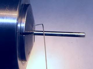
The needle for the fuel control needle valve is about as easy as it gets.
I started off with a length of 1/16 inch diameter straightened music wire from the local hobby shop. Marked off 2 inches and cut it off by clamping in my small drill press vice and cutting with a abrasive cut off wheel in a Dremel tool. The ends were cleaned up on the bench grinder and one end was rounded and polished for the handle end.
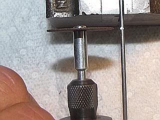
The wire was transferred to the lathe where the taper on the end was ground with a fine grit wheel in the Dremel. Before grinding, the grinding wheel was trued up using the same diamond dressing tool I use on the bench grinder. It was trued up by hand so while it is round the working face is not very flat. By keeping the grinding wheel moving, a reasonable taper is generated. Since I ground the needle by hand the dimensions are eyeball approximations. After grinding to shape, I dressed the needle to a finer finish and more even taper using a EZ-Lap 1/4 inch square 600 grit diamond lap.
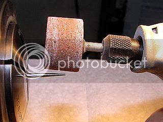
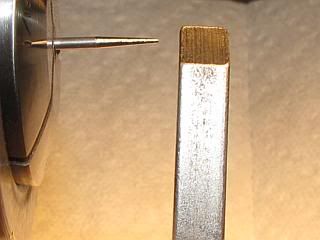
Then it was polished with 1200 grit abrasive paper. When finished I could not feel any roughness with my fingernail. Finally I polished the entire shank of the needle with abrasive paper to remove any surface contamination so it can be soldered into the barrel (to be made next).
Gail in NM
Now I am down to easy parts.
The needle for the fuel control needle valve is about as easy as it gets.
I started off with a length of 1/16 inch diameter straightened music wire from the local hobby shop. Marked off 2 inches and cut it off by clamping in my small drill press vice and cutting with a abrasive cut off wheel in a Dremel tool. The ends were cleaned up on the bench grinder and one end was rounded and polished for the handle end.
The wire was transferred to the lathe where the taper on the end was ground with a fine grit wheel in the Dremel. Before grinding, the grinding wheel was trued up using the same diamond dressing tool I use on the bench grinder. It was trued up by hand so while it is round the working face is not very flat. By keeping the grinding wheel moving, a reasonable taper is generated. Since I ground the needle by hand the dimensions are eyeball approximations. After grinding to shape, I dressed the needle to a finer finish and more even taper using a EZ-Lap 1/4 inch square 600 grit diamond lap.
Then it was polished with 1200 grit abrasive paper. When finished I could not feel any roughness with my fingernail. Finally I polished the entire shank of the needle with abrasive paper to remove any surface contamination so it can be soldered into the barrel (to be made next).
Gail in NM
- Joined
- Feb 17, 2008
- Messages
- 2,330
- Reaction score
- 445
Ron: I am glad that this is helping you some.
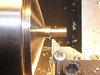
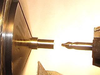
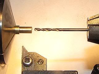
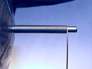
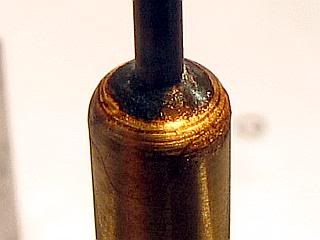
Next up is the barrel that holds the needle.
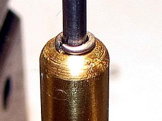
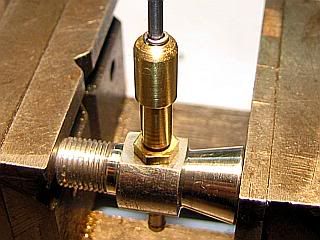
A few operations, but all are easy. 3/16 diameter brass stock was cut to length and it turned down for a 1/4 inch so the spring will slide over it. Center drill, drill to tap 5-40 and then tap. Drill through with 1/16 drill bit for the needle. Reverse in the lathe and file the end to round it off just for looks. Where the 1/16 hole broke through, the hole is deburred using a small center drill and counter sunk a little bit (5 to 10 thou) to help guide solder at assembly. I just hold the center drill in my fingers to do this.
Gail in NM
Next up is the barrel that holds the needle.
A few operations, but all are easy. 3/16 diameter brass stock was cut to length and it turned down for a 1/4 inch so the spring will slide over it. Center drill, drill to tap 5-40 and then tap. Drill through with 1/16 drill bit for the needle. Reverse in the lathe and file the end to round it off just for looks. Where the 1/16 hole broke through, the hole is deburred using a small center drill and counter sunk a little bit (5 to 10 thou) to help guide solder at assembly. I just hold the center drill in my fingers to do this.
Gail in NM
- Joined
- Feb 17, 2008
- Messages
- 2,330
- Reaction score
- 445
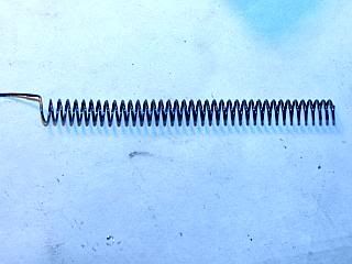
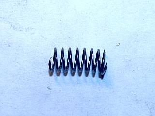
Last item (I think) is the spring. It could probably come out of one of the junk drawers or be rescued from a ball point pen, but I have found that I can make three up in the time it takes to find one.
The purpose of the spring is to keep the needle valve from changing position from engine vibration.
I used a long 1/8 inch dowel pin to form the spring on. When the spring relaxes from being wound the ID will be close to the 0.141 dimension that is desired.
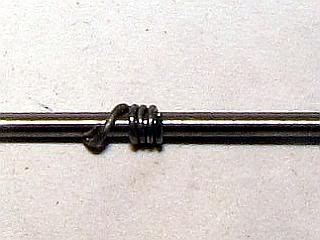
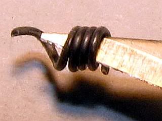
Starting off with about 2 feet of 0.018 music wire, I bent a hook on one end and gripped the other end in a locking set of pliers. With the dowel pin gripped in the collet of the lathe, I inserted the bent end in one of the collet splits and put tension on the wire. My lathe goes down to about 40 RPM, so setting at low speed I ran it in reverse to wind the wire on the mandrel. If you are trying this, and your lathe will not go below 100 RPM, I would suggest that you use regular pliers and not locking pliers. This is so you can just let go of the wire. When you let go of the wound spring, it will unwind and the loose end can whip around and cut you. Be careful.
As I close wound the spring, I then stretched it out so 10 turns filled half an inch. Using heavy duty cutters, I snipped off a 10 turn length. Put the spring on the mandrel to provide support and a place to grip and then ground the end off a little bit to flatten it so it would turn smoothly on surfaces it will be bearing on.
Gail in NM
The purpose of the spring is to keep the needle valve from changing position from engine vibration.
I used a long 1/8 inch dowel pin to form the spring on. When the spring relaxes from being wound the ID will be close to the 0.141 dimension that is desired.
Starting off with about 2 feet of 0.018 music wire, I bent a hook on one end and gripped the other end in a locking set of pliers. With the dowel pin gripped in the collet of the lathe, I inserted the bent end in one of the collet splits and put tension on the wire. My lathe goes down to about 40 RPM, so setting at low speed I ran it in reverse to wind the wire on the mandrel. If you are trying this, and your lathe will not go below 100 RPM, I would suggest that you use regular pliers and not locking pliers. This is so you can just let go of the wire. When you let go of the wound spring, it will unwind and the loose end can whip around and cut you. Be careful.
As I close wound the spring, I then stretched it out so 10 turns filled half an inch. Using heavy duty cutters, I snipped off a 10 turn length. Put the spring on the mandrel to provide support and a place to grip and then ground the end off a little bit to flatten it so it would turn smoothly on surfaces it will be bearing on.
Gail in NM
That spring came out nice, Gail, (along with everything else you've made here!)
I've made a few springs, and thought I would just mention this for some who might wonder where to get music wire; Down to a pretty small size can be had a many hobby shops. If you need very small wire, check a music store. You can get really small sizes of music wire in the form of guitar and mandolin strings. Cheap too!
Dean
- Joined
- Feb 17, 2008
- Messages
- 2,330
- Reaction score
- 445
Good info Dean. Thanks.
I think that my local hobby shop has wire down to 0.010 diameter. I know they have 0.015 and 0.020 wire, either of which would work for this spring. I was fortunate to buy a box of assorted 1/4 pound spools of music wire ranging from o.005 to 0.047 at a auction of a machine shop that was being liquidated about 20 years ago. I have not even put a dent in this stash yet.
Gail in NM
- Joined
- Feb 17, 2008
- Messages
- 2,330
- Reaction score
- 445
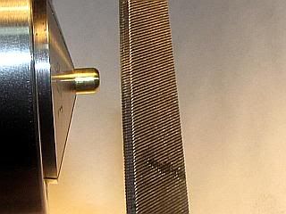
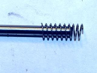
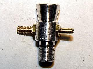
On to the assembly of the fuel system.
First the spray bar was installed in the venturi. The cross hole should be pointed at the side of the tube, but it is not critical. If you can not see the hole looking in the air inlet side then it is OK. Drilling the hole the way I did places the hole in line with one of the points of the hex portion of the spray bar, so alignment is easy.
The barrel is threaded on the spray bar until it bottoms and then it is backed off one turn. This leaves one turn to make sure the valve can be shut off all the way. The needle is inserted into the barrel and pushed all the way down. Then it is retracted a little bit, about an 1/8 inch and flux applied to the needle next to the barrel. Working the needle in and out of the barrel a little bit to distribute the flux in the hole, the needle is reseated all the way down and the excess flux is wiped off.
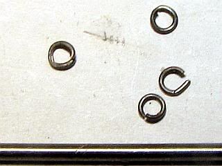
A ring of solder is made by winding a short length of 0.015 solder several turns around a piece of 1/16 wire, and then cutting it into rings with a hobby knife inserted into the coil after removing the coil from the wire. One of the rings is then slid on the needle down to the barrel.
The barrel is heated with a small torch until the solder melts and flows down into the joint. After cooling, I removed the flux residue with a bit of alcohol and a paper towel.
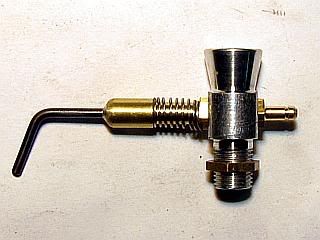
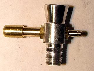
The needle was removed from the spraybar and the end of the needle is bent to about a 45 degree angle to form a handle. The needle was left out at this point as it will not clear the mounting lugs on the crankcase when installing the venturi on the crankcase.
The 1/4-40 nut was installed on the venturi and then the venturi was screwed into the crankcase and turned to the desired poslition and the nut tightened. After sliding the spring on the needle, the needle was reinstalled.
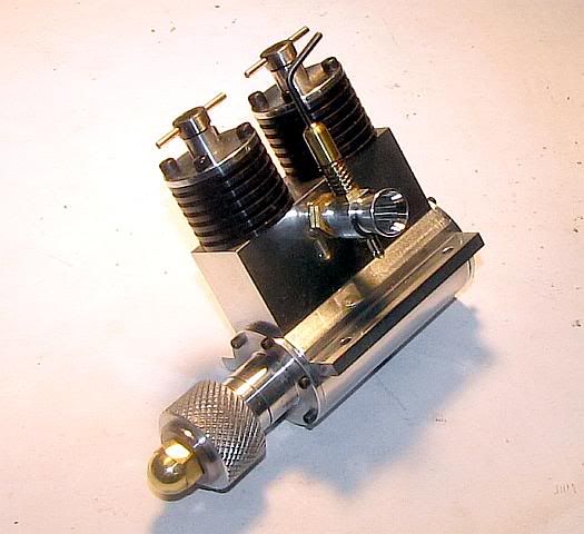
The engine is now finished and ready for a test run.
Gail in NM
First the spray bar was installed in the venturi. The cross hole should be pointed at the side of the tube, but it is not critical. If you can not see the hole looking in the air inlet side then it is OK. Drilling the hole the way I did places the hole in line with one of the points of the hex portion of the spray bar, so alignment is easy.
The barrel is threaded on the spray bar until it bottoms and then it is backed off one turn. This leaves one turn to make sure the valve can be shut off all the way. The needle is inserted into the barrel and pushed all the way down. Then it is retracted a little bit, about an 1/8 inch and flux applied to the needle next to the barrel. Working the needle in and out of the barrel a little bit to distribute the flux in the hole, the needle is reseated all the way down and the excess flux is wiped off.
A ring of solder is made by winding a short length of 0.015 solder several turns around a piece of 1/16 wire, and then cutting it into rings with a hobby knife inserted into the coil after removing the coil from the wire. One of the rings is then slid on the needle down to the barrel.
The barrel is heated with a small torch until the solder melts and flows down into the joint. After cooling, I removed the flux residue with a bit of alcohol and a paper towel.
The needle was removed from the spraybar and the end of the needle is bent to about a 45 degree angle to form a handle. The needle was left out at this point as it will not clear the mounting lugs on the crankcase when installing the venturi on the crankcase.
The 1/4-40 nut was installed on the venturi and then the venturi was screwed into the crankcase and turned to the desired poslition and the nut tightened. After sliding the spring on the needle, the needle was reinstalled.
The engine is now finished and ready for a test run.
Gail in NM
LADmachining
Well-Known Member
- Joined
- Sep 22, 2009
- Messages
- 53
- Reaction score
- 11
Will it be test-run today?? ")
Well done Gail, some excellent work there!
Anthony
Well done Gail, some excellent work there!
Anthony
Similar threads
- Replies
- 7
- Views
- 3K
- Replies
- 1
- Views
- 2K
- Replies
- 7
- Views
- 3K