
You are using an out of date browser. It may not display this or other websites correctly.
You should upgrade or use an alternative browser.
You should upgrade or use an alternative browser.
Lobo Pup Twin 1.6 cc diesel
- Thread starter GailInNM
- Start date


Help Support Home Model Engine Machinist Forum:
This site may earn a commission from merchant affiliate
links, including eBay, Amazon, and others.
- Joined
- Feb 17, 2008
- Messages
- 2,330
- Reaction score
- 445
Thank you Jack, Ron, Tom and DIY for following along. It's nice to know that I am not just writing a personal diary. I am not much of a wordsmith, but I have fun trying and although I don't expect anyone to duplicate this engine I hope that it gives people ideas to try on their own.
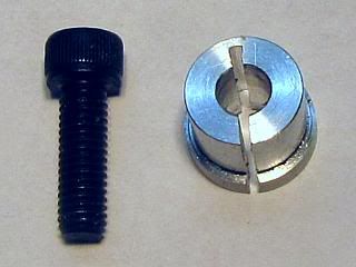
To finish up the top end of the engine is the Compression adjustment screw and compression limiter spacer. Mine is a little more complicated than some, but there is a reason for all of it. I have seen engines that just have a plain screw stuck in the top, but besides not looking very good that does not really work very well. A normal screw is not very flat on the end so it does not make good contact with the contra-piston. This sometimes causes it to change adjustment when the engine is running. Also, a tool of some kind is required to adjust it. Sometimes two tools if a lock nut is also put on. This is awkward and not very safe when reaching over a spinning propeller to make the adjustment.
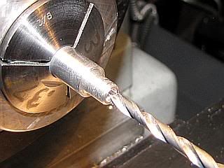
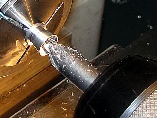
So, the first thing is to trim the screw to length and face the end. I made a split collet out of aluminum to hold the screw. I started off with a 10-32 x 5/8 socket head cap screw. The threads are relieved down to the minor diameter of the screw so the end is a round where it contacts the contra-piston. A small hole is put in the center of the end to remove any cut off pip that may occur when facing the end and to clear any pip that may be on the contra-piston. Then the end is polished a little bit with abrasive paper to remove any burrs.
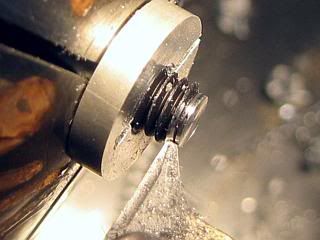
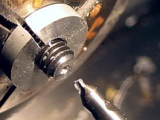
With both screws done, a screw in inserted part way into each cylinder head. From this point on, it is necessary to keep each screw associated with it's respective cylinder. I do this by only working on one screw at a time, and then returning to it's respective cylinder before removing the other screw. The crankshaft is rotated until one of the pistons is near top dead center (TDC). By looking in the exhaust ports it is easy to determine which one is at TDC because the other piston will be below the exhaust port. While rocking the crankshaft around TDC, the compression screw for that cylinder is adjusted until the piston strikes the contra-piston. Back off the adjustment screw a little bit and again rock the crankshaft about TDC. This will force the contra-piston up until the piston and contra piston just touch. The adjustment screw is then rotated back down with fingers until it touches but does not move the contra-piston. The same operation is repeated for the other cylinder. Now the distance from the screw head to the top of the cylinder head is measured on each cylinder and written down.
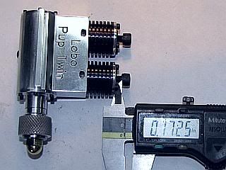
The compression limiters can be made up now or later after the adjustment screws are finished. The construction was not photographed, but they are made from 1/4 diameter rod drilled to clear the adjustment screws. They are then parted off to the length that is equal to what was measured plus 0.010 inch. This makes sure that the contra-piston can not be adjusted closer to the piston than 0.010 inch. Calculated piston to contra-piston distance for running is 0.025 inch, so normal operation SHOULD be about a half turn above this, but initial starting trials will be set above this. One end of the limiters needs to be countersunk a little bit to clear the radius that is present between the head and shank of most screws. I countersunk both ends so I did not have to keep track of which way was up.
Gail in NM
To finish up the top end of the engine is the Compression adjustment screw and compression limiter spacer. Mine is a little more complicated than some, but there is a reason for all of it. I have seen engines that just have a plain screw stuck in the top, but besides not looking very good that does not really work very well. A normal screw is not very flat on the end so it does not make good contact with the contra-piston. This sometimes causes it to change adjustment when the engine is running. Also, a tool of some kind is required to adjust it. Sometimes two tools if a lock nut is also put on. This is awkward and not very safe when reaching over a spinning propeller to make the adjustment.
So, the first thing is to trim the screw to length and face the end. I made a split collet out of aluminum to hold the screw. I started off with a 10-32 x 5/8 socket head cap screw. The threads are relieved down to the minor diameter of the screw so the end is a round where it contacts the contra-piston. A small hole is put in the center of the end to remove any cut off pip that may occur when facing the end and to clear any pip that may be on the contra-piston. Then the end is polished a little bit with abrasive paper to remove any burrs.
With both screws done, a screw in inserted part way into each cylinder head. From this point on, it is necessary to keep each screw associated with it's respective cylinder. I do this by only working on one screw at a time, and then returning to it's respective cylinder before removing the other screw. The crankshaft is rotated until one of the pistons is near top dead center (TDC). By looking in the exhaust ports it is easy to determine which one is at TDC because the other piston will be below the exhaust port. While rocking the crankshaft around TDC, the compression screw for that cylinder is adjusted until the piston strikes the contra-piston. Back off the adjustment screw a little bit and again rock the crankshaft about TDC. This will force the contra-piston up until the piston and contra piston just touch. The adjustment screw is then rotated back down with fingers until it touches but does not move the contra-piston. The same operation is repeated for the other cylinder. Now the distance from the screw head to the top of the cylinder head is measured on each cylinder and written down.
The compression limiters can be made up now or later after the adjustment screws are finished. The construction was not photographed, but they are made from 1/4 diameter rod drilled to clear the adjustment screws. They are then parted off to the length that is equal to what was measured plus 0.010 inch. This makes sure that the contra-piston can not be adjusted closer to the piston than 0.010 inch. Calculated piston to contra-piston distance for running is 0.025 inch, so normal operation SHOULD be about a half turn above this, but initial starting trials will be set above this. One end of the limiters needs to be countersunk a little bit to clear the radius that is present between the head and shank of most screws. I countersunk both ends so I did not have to keep track of which way was up.
Gail in NM
zeeprogrammer
Well-Known Member
- Joined
- Mar 14, 2009
- Messages
- 3,362
- Reaction score
- 13
I try to read everything you post Gail. Apart from the occasional question, I find it very difficult to come up with a meaningful comment. Please keep the 'diary' going...I'm sure I'm not the only who's trying to get a word out while trying to pick up their jaw.
vlmarshall
Well-Known Member
- Joined
- Dec 28, 2008
- Messages
- 1,138
- Reaction score
- 1
zeeprogrammer said:I try to read everything you post Gail. Apart from the occasional question, I find it very difficult to come up with a meaningful comment. Please keep the 'diary' going...I'm sure I'm not the only who's trying to get a word out while trying to pick up their jaw.
...yeah, what HE said. Great stuff, keep it up, please!
arnoldb
Well-Known Member
- Joined
- Apr 8, 2009
- Messages
- 1,792
- Reaction score
- 12
Thank you Gail - once again very well done and documented.
You are most definitely not just writing a diary; following along on your build is a real treat, and most definitely on my own to-build list.
Kind Regards, Arnold
You are most definitely not just writing a diary; following along on your build is a real treat, and most definitely on my own to-build list.
Kind Regards, Arnold
- Joined
- Feb 17, 2008
- Messages
- 2,330
- Reaction score
- 445
Thanks to Zee, Vernon and Arnold. Like you, I read most posts on the forum, but respond to only a small percentage of them.
Re-reading the first part of my last post, it sounds like I was fishing for comments. Actually, I was trying to be humorous (poorly). But, comments are always helpful. It lets me know if I am including enough detail, or too much detail. Too little and the beginners get lost and too much bores the experts. And since this is both a design and build thread, I have tried to explain why I do things as well as just how I do things.
So without the humor, on to finishing up the top end of the Lobo.
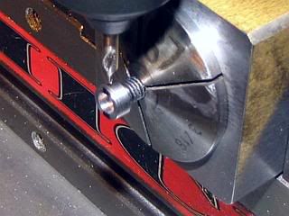
The only thing left topside is to finish off the compression adjustment screws. Note to self: keep the screws associated with each cylinders during these operations.
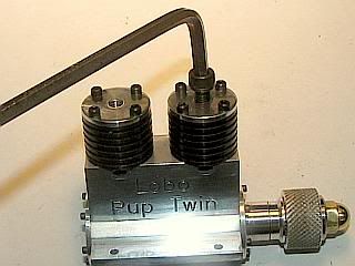
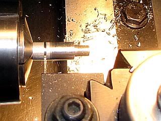
I faced off the top of the head and turned the knurled part off the head. Then bored to remove the hex part inside so the drill would not be deflected when drilling the cross hole.
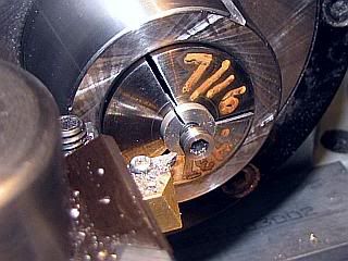
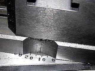
The screws were reinstalled in their cylinders and run down with fingers until they touched the contra-piston. I marked the screws with a felt marker with a line from the front to back of the engine. Each screw was installed in a collet block in the mill with the marks vertical and center drilled and drilled.
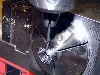
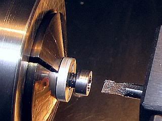
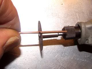
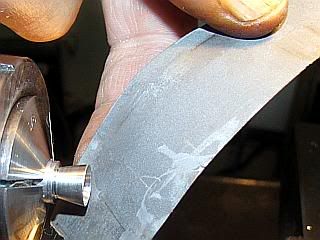
The handle was cut from music wire with a rotary tool (Dremel) and a cutoff wheel. It was cut a little long and then brought to size on the bench grinder and the ends rounded off and polished so they would not act like a cutting tool on bare finger tips when adjusting on a vibrating engine.
The handle was pressed into the crosshole on the adjusting screw and secured with a little bit of epoxy run down to fill the hole in the head of the adjusting screw. The hole was overfilled so epoxy was above the head. After curing , the epoxy was faced off in the lathe so it was flush with the top of the screw.
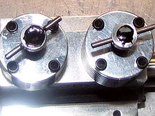
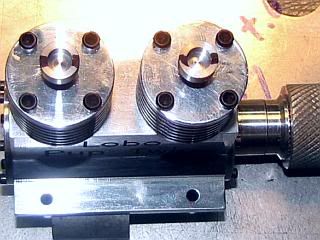
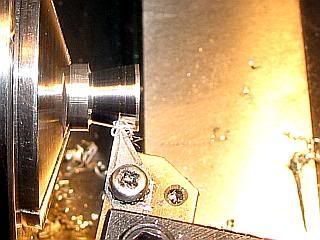
With the compression limiters installed on their respective screw, the screws were reinstalled in the cylinders and run down to the compression limiters. The reason for all the effort to align the holes in the adjustment screws was so the handles would be in approximately the same place during the running of the engine. Notice that since the compression limiters are 0.010 longer than where the screws were marked the compression screws are about 1/3 of a turn up in the photo from where they were marked ( 0.01 x thread turns per inch = 0.01 x 32 = 1/3 close enough). It is anticipated that when the engine is adjusted while running that these screws will be about 1/2 further out from here. We will see.
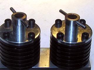
Gail in NM
Re-reading the first part of my last post, it sounds like I was fishing for comments. Actually, I was trying to be humorous (poorly). But, comments are always helpful. It lets me know if I am including enough detail, or too much detail. Too little and the beginners get lost and too much bores the experts. And since this is both a design and build thread, I have tried to explain why I do things as well as just how I do things.
So without the humor, on to finishing up the top end of the Lobo.
The only thing left topside is to finish off the compression adjustment screws. Note to self: keep the screws associated with each cylinders during these operations.
I faced off the top of the head and turned the knurled part off the head. Then bored to remove the hex part inside so the drill would not be deflected when drilling the cross hole.
The screws were reinstalled in their cylinders and run down with fingers until they touched the contra-piston. I marked the screws with a felt marker with a line from the front to back of the engine. Each screw was installed in a collet block in the mill with the marks vertical and center drilled and drilled.
The handle was cut from music wire with a rotary tool (Dremel) and a cutoff wheel. It was cut a little long and then brought to size on the bench grinder and the ends rounded off and polished so they would not act like a cutting tool on bare finger tips when adjusting on a vibrating engine.
The handle was pressed into the crosshole on the adjusting screw and secured with a little bit of epoxy run down to fill the hole in the head of the adjusting screw. The hole was overfilled so epoxy was above the head. After curing , the epoxy was faced off in the lathe so it was flush with the top of the screw.
With the compression limiters installed on their respective screw, the screws were reinstalled in the cylinders and run down to the compression limiters. The reason for all the effort to align the holes in the adjustment screws was so the handles would be in approximately the same place during the running of the engine. Notice that since the compression limiters are 0.010 longer than where the screws were marked the compression screws are about 1/3 of a turn up in the photo from where they were marked ( 0.01 x thread turns per inch = 0.01 x 32 = 1/3 close enough). It is anticipated that when the engine is adjusted while running that these screws will be about 1/2 further out from here. We will see.
Gail in NM


$40.02
$49.99
Becker CAD 12 3D - professional CAD software for 2D + 3D design and modelling - for 3 PCs - 100% compatible with AutoCAD
momox Shop


![DreamPlan Home Design and Landscaping Software Free for Windows [PC Download]](https://m.media-amazon.com/images/I/51kvZH2dVLL._SL500_.jpg)
$0.00
DreamPlan Home Design and Landscaping Software Free for Windows [PC Download]
Amazon.com Services LLC


$89.99
Outdoor Wood Boiler Water Treatment Rust Inhibitor- AmTech 300 & Test Kit
Alternative Heating & Supplies

$12.56
$39.95
Complete Plans for Building Horse Barns Big and Small(3rd Edition)
ThriftBooks-Atlanta

![MeshMagic 3D Free 3D Modeling Software [Download]](https://m.media-amazon.com/images/I/B1U+p8ewjGS._SL500_.png)

$39.99
$49.99
Sunnytech Low Temperature Stirling Engine Motor Steam Heat Education Model Toy Kit For mechanical skills (LT001)
stirlingtechonline


$29.95
Competition Engine Building: Advanced Engine Design and Assembly Techniques (Pro Series)
Amazon.com Services LLC

$24.99
$27.99
HOZLY 5PCS/Lot ISO30 Tool Holder Clamp Flame Proof Rubber Claw CNC Machines Automatic Tool Changer
HOZLY

$94.99
$109.99
AHS Woodmaster 4400 Maintenance Kit for Outdoor Wood Boiler Treatment
Alternative Heating & Supplies


$519.19
$699.00
FoxAlien Masuter Pro CNC Router Machine, Upgraded 3-Axis Engraving All-Metal Milling Machine for Wood Acrylic MDF Nylon Carving Cutting
FoxAlien Official


$24.99
$34.99
Bowl Sander Tool Kit w/Dual Bearing Head & Hardwood Handle | 42PC Wood Sander Set | 2" Hook & Loop Sanding Disc Sandpaper Assortment | 1/4" Mandrel Bowl Sander for Woodturning | Wood Lathe Tools
Peachtree Woodworking Supply Inc


$99.99
AHS Outdoor Wood Boiler Yearly Maintenance Kit with Water Treatment - ProTech 300 & Test Kit
Alternative Heating & Supplies


zeeprogrammer
Well-Known Member
- Joined
- Mar 14, 2009
- Messages
- 3,362
- Reaction score
- 13
Well I can say "It's just right for me!" Excellent pics, good writing, wonderful detail. Very enjoyable.
I know what you mean...hard to judge sometimes if what one is doing is good, acceptable, decent, or whatever.
I know what you mean...hard to judge sometimes if what one is doing is good, acceptable, decent, or whatever.
I'm watching too, Gail. Though I don't always have a comment for your posts, I am enjoying watching a competent machinist go about his work.
The engine is quite a piece of work, and I see a lot of good procedure in your write up. All of us can learn something here.
(And I didn't think you were fishing either, but I know what you mean!)
Dean
The engine is quite a piece of work, and I see a lot of good procedure in your write up. All of us can learn something here.
(And I didn't think you were fishing either, but I know what you mean!)
Dean
")
Hi Gail - I have been following your thread with great interest and I beleive that you are grossly mistaken in the statement made that "no one will attempt to duplicate this engine". I believe that once the plans are finalized it will just be a matter of time until builds of this engine will start appearing on HMEM as well as many other homepages on the internet. Keep up the good work and I for one will be looking forward to your first successful run. - Billmc
I've want to build an inline twin for a while. I've yet to build a whole engine. I keep putting it off trying to decide what I want to build. I have plenty of projects modifying model airplane engines. Anyway, this build looks like something I might do. It looks great and I can't wait to hear it run.
Greg
Greg
Gail,
The engine is looking great. I have learnt a lot from reading your posts. Do you always prefer to use collets rather than a 3 jaw. Suppose once it is set up you have the accuracy and repeatability at your finger tips you won't go back to a 3 jaw?
I agree on the tolerancing - horses for courses. I've just realised recently that I waste a lot of time trying to hit dimensions that don't need to be hit, aren't critical. I think it's maybe an OCD of mine!
Considering you don't like polishing it's looking pretty shiny! Must be the superb workmanship. I'm of the same vane though, a nice engineering finish will do me, not into mirror finishes and bling and it's always more satisfying if it comes from the lathe and you don't need to do anything further! Wish that happened with me all the time but I can't claim that it does!
Nick
- Joined
- Feb 17, 2008
- Messages
- 2,330
- Reaction score
- 445
Thanks for all the comments and support.
Zee: I have followed your posts from when you first joined. You are making great progress. You have reached the point where you can question authority in an educated manner and that makes you a good proofreader. If anything is not clear be sure to let me know. It helps both me and others.
Dean: I don't know about the "competent machinist " part. I am strictly self taught, but I have been at it for a long time so I just know what works for me, and more importantly what does not work for me.
Ariz: The work you have shown on HMEM speaks for it's self, so I consider the fact that you have been following this thread a great compliment.
Bill: I have been keeping the drawings on my computer updated as I go along. Assuming that the engine is successful, and I think that it will be, I will replace all the preliminary drawings that are posted with a set of "as built" drawings. There are about 20 changes that I have made to them as I went along. None of them serious. Mostly clarifications on dimensions and a few things to make machining easier. And a couple of "what was I thinking" when I drew it that way.
Dieselpilot: It's getting close to the time for you to build an engine from scratch. I know that you have worked on enough engines to know what you want, but I would suggest that you start with a single cylinder for your first engine. After the Lobo Twin is finished, I may do a single cylinder version of it. Nothing definite yet, but I made a few extras of the parts which would be common.
Nick: As you noticed, I use collets most of the time. Since I build small toys, 5C collets will take care of 95 percent of the lathe work that I do. I have a full set in 1/64 increments plus common size hex and square. For odd small sizes, I have a ER16 holder that I put in a 5C collet. I do have both a 6 jaw and 4 jaw chuck that I use for larger and odd shaped parts and for eccentric turning. Also a faceplate when all else fails. My lathe has a 5C spindle, so there is no adapter to fuss with, and to install a chuck is only a 30 second job including cleaning the mating taper and faces. Ease of change over was one of the things I was looking for when I bought this lathe a few years ago. The 5C collets have served me well over the years. In addition to the lathe, I use them in a Spindex, collets blocks, and my indexing head. I just bought what I needed at the time over many years and then a couple of years ago I filled in the set with low cost collets for the odd sizes.
Enough small talk. I will start posting the remaining seven parts that are necessary for the fuel system later today. Then I will be approaching the moment of truth.
Gail in NM
- Joined
- Feb 17, 2008
- Messages
- 2,330
- Reaction score
- 445
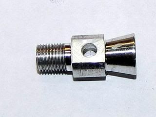
The last group of parts are for the fuel system. The most visible of these parts is the venturi that everything else mounts to, either directly or indirectly.
The venturi has no critical dimensions. The 1/4-40 thread has to fit the crankcase and the axial hole in it should be reasonable close. Most of the venturi action is created by the reduced cross section caused by the spraybar passing through the axial hole. The air intake or bell portion of the venturi can be any shape or even left as just the axial hole. On a higher performance engine all these things get far more critical but this engine will probably only reach about 10,000 RPM.
I started the venturi with length of 3/8 diameter aluminum bar. One end was turned down and threaded with a 1/40 die. I use the front of my tail stock chuck with the jaws retracted to start the die square.
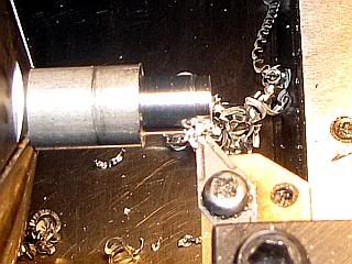
After center drilling and drilling, the part is cut off a little long to allow cleaning up to length.
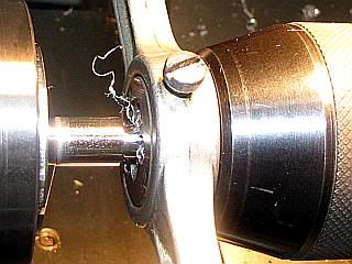
After switching ends, the part is faced off to length. The compound slide is set to 12 degrees for an included angle of 24 degrees and the exterior of the bell is cut using the compound slide. Nothing critical about the angle. It is only for looks.
The end was opened up with a 60 degree countersink. The shallow angle is just for looks. A standard 87 degree would work just as well. A small boring bar could also be used to generate an angle, or the hole could be left plain but it would not look very good to my eye. I then rounded off the sharp edges and did a light polish with abrasive paper.
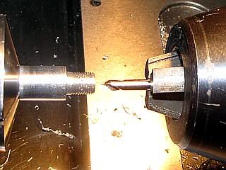
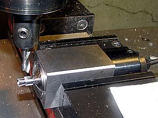
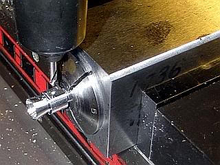
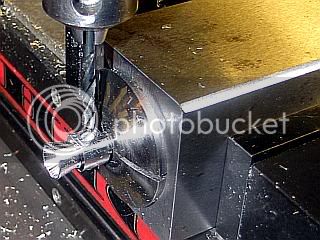
After transferring to a collet block in the mill the two sides are faced off to provide flat mounting surfaces for the spraybar. The collet block was positioned by a stop on the vice to make it easy to flip the block 180 degrees to do the second side. The center flat surface is center drilled and drilled for the spray bar. After removal from the collet, the axial hole is deburred on the inside using the same drill that was used to drill it.
Gail in NM
The venturi has no critical dimensions. The 1/4-40 thread has to fit the crankcase and the axial hole in it should be reasonable close. Most of the venturi action is created by the reduced cross section caused by the spraybar passing through the axial hole. The air intake or bell portion of the venturi can be any shape or even left as just the axial hole. On a higher performance engine all these things get far more critical but this engine will probably only reach about 10,000 RPM.
I started the venturi with length of 3/8 diameter aluminum bar. One end was turned down and threaded with a 1/40 die. I use the front of my tail stock chuck with the jaws retracted to start the die square.
After center drilling and drilling, the part is cut off a little long to allow cleaning up to length.
After switching ends, the part is faced off to length. The compound slide is set to 12 degrees for an included angle of 24 degrees and the exterior of the bell is cut using the compound slide. Nothing critical about the angle. It is only for looks.
The end was opened up with a 60 degree countersink. The shallow angle is just for looks. A standard 87 degree would work just as well. A small boring bar could also be used to generate an angle, or the hole could be left plain but it would not look very good to my eye. I then rounded off the sharp edges and did a light polish with abrasive paper.
After transferring to a collet block in the mill the two sides are faced off to provide flat mounting surfaces for the spraybar. The collet block was positioned by a stop on the vice to make it easy to flip the block 180 degrees to do the second side. The center flat surface is center drilled and drilled for the spray bar. After removal from the collet, the axial hole is deburred on the inside using the same drill that was used to drill it.
Gail in NM
zeeprogrammer
Well-Known Member
- Joined
- Mar 14, 2009
- Messages
- 3,362
- Reaction score
- 13
What kind of aluminum bar did you use? Did you do something else besides use abrasive paper to get such a finish?
You mentioned setting the component slide 12 degrees for an included angle of 24...would you explain that a little more?
Thanks Gail.
You mentioned setting the component slide 12 degrees for an included angle of 24...would you explain that a little more?
Thanks Gail.
Gail, Yes, it's time to build an engine, before my second little one comes in March. I'm bringing my Clausing 4904 into service this week. I got the carriage cleaned up and back on the ways last night. I'll finish assembling the top slide and compound tonight. And hopefully finish the backplate for the Sjogren 5C chuck after that. 1" through spindle should come in handy, no more sawing 1" 4340 by hand. I don't think my old Altas will make engines anymore. Now to decide what I'm going to build. The only thing I haven't made yet is rings or a lapped piston/liner. I think I can handle everything else.
I use the tailstock chuck trick for squaring dies too.
I use the tailstock chuck trick for squaring dies too.
zeeprogrammer said:You mentioned setting the component slide 12 degrees for an included angle of 24...would you explain that a little more?
Thanks Gail.
Zee, Gail set the compound slide to cut a 12 degree taper. When he cut that taper on the venturi, it makes a mirror image of the angle on the other side of the piece. In other words, it's cut 12 deg all around. When you measure the complete angle of the venturi bell, it will be 24 degrees in relation to the center line of the piece. 12+12=24.
Prints often say to cut an angle to "XX (included angle)". That's letting you know that you need to cut 1/2X to get the angle call out on the print.
If you look in the tool sales web sites, and go to the dead centers, you will see the description for the dead center often will say 60 deg (included angle). It lets you know that the complete angle is 60 deg, not just one leg of the angle.
Dean
zeeprogrammer
Well-Known Member
- Joined
- Mar 14, 2009
- Messages
- 3,362
- Reaction score
- 13
Ah. Thanks for that Dean.
Similar threads
- Replies
- 7
- Views
- 3K
- Replies
- 1
- Views
- 2K
- Replies
- 7
- Views
- 3K