
You are using an out of date browser. It may not display this or other websites correctly.
You should upgrade or use an alternative browser.
You should upgrade or use an alternative browser.
Lobo Pup Twin 1.6 cc diesel
- Thread starter GailInNM
- Start date


Help Support Home Model Engine Machinist Forum:
This site may earn a commission from merchant affiliate
links, including eBay, Amazon, and others.
- Joined
- Feb 17, 2008
- Messages
- 2,330
- Reaction score
- 445
Thanks for the kind comment Gordy.
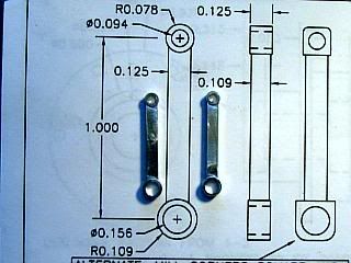
With the crankcase finished, it is time to start filling it up. First up is the connecting rod, sheet 3-1.
The connecting rod is selected as the first item as the holes in it are reamed, and there is not much that can be done about the hole sizes. By making it first, we can offer it up to the crank pins on the crankshafts to test their size, and those we can do something about.
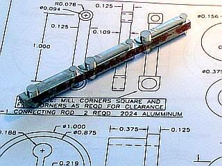
I made the connecting rods on the CNC mill. If I were making just one I would normally do it manually, rounding the ends with a file and filing buttons. Doing two, it takes about the same time either manual or CNC, but I like to have a spare so that makes three, and now CNC is quicker. Those with keen eyes will notice in one of the photos that I flipped the blank over when cutting the profile, so now I have six. This is because I was sketching on the back of an envelope last night and have an idea that may be able to use a couple more of them. Once I am this far, why not.
The connecting rod and the rounding of the crankcase bottom will probably be the only parts where I use CNC. It is certainly not essential, but since I have it I use it to save time.
The connecting rod is about the only part that I am fussy about the material. It is highly stressed and needs to have good bearing qualities on the unhardened steel crankpin. 2024 aluminum is my material of choice for this.
I started off with a piece of 1/4 X 1/2 a little over 4 inches long. Sitting it on a parallel, I cleaned up the surface and profiled three rods along the edge of the strip and relieved the rod between the ends so the rod will not rub on the crankdisk. Flipped it over and did the same thing to the other edge.
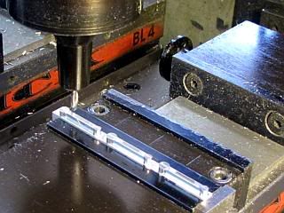
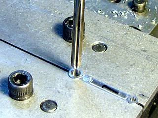
I sawed the rods apart on a bandsaw. A pocket was cut into a softjaw to hold the part. The part was faced off and the rod section between the ends relieved. The holes are "drilled" using a 3/32 and 5/32 end mill. Like most end mills, the ones I have are slightly under size and this leaves a little bit to bring the holes to size with a reamer.
After reaming, the parts are cleaned up with some 400 grit abrasive paper to remove burrs and each hole is lightly touched with a small hand held countersink to remove any burrs and sharp edges.
Gail in NM
With the crankcase finished, it is time to start filling it up. First up is the connecting rod, sheet 3-1.
The connecting rod is selected as the first item as the holes in it are reamed, and there is not much that can be done about the hole sizes. By making it first, we can offer it up to the crank pins on the crankshafts to test their size, and those we can do something about.
I made the connecting rods on the CNC mill. If I were making just one I would normally do it manually, rounding the ends with a file and filing buttons. Doing two, it takes about the same time either manual or CNC, but I like to have a spare so that makes three, and now CNC is quicker. Those with keen eyes will notice in one of the photos that I flipped the blank over when cutting the profile, so now I have six. This is because I was sketching on the back of an envelope last night and have an idea that may be able to use a couple more of them. Once I am this far, why not.
The connecting rod and the rounding of the crankcase bottom will probably be the only parts where I use CNC. It is certainly not essential, but since I have it I use it to save time.
The connecting rod is about the only part that I am fussy about the material. It is highly stressed and needs to have good bearing qualities on the unhardened steel crankpin. 2024 aluminum is my material of choice for this.
I started off with a piece of 1/4 X 1/2 a little over 4 inches long. Sitting it on a parallel, I cleaned up the surface and profiled three rods along the edge of the strip and relieved the rod between the ends so the rod will not rub on the crankdisk. Flipped it over and did the same thing to the other edge.
I sawed the rods apart on a bandsaw. A pocket was cut into a softjaw to hold the part. The part was faced off and the rod section between the ends relieved. The holes are "drilled" using a 3/32 and 5/32 end mill. Like most end mills, the ones I have are slightly under size and this leaves a little bit to bring the holes to size with a reamer.
After reaming, the parts are cleaned up with some 400 grit abrasive paper to remove burrs and each hole is lightly touched with a small hand held countersink to remove any burrs and sharp edges.
Gail in NM
- Joined
- Feb 17, 2008
- Messages
- 2,330
- Reaction score
- 445
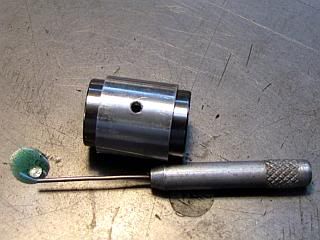
Before making the rest of the parts that fill up the crankcase bottom, I made the four jigs and fixtures that are required to machine the parts and assemble them. Two are the split offset collets that are used to machine the crankpins on the center crankshafts. They are shown on sheet 3 of the drawings and are identical except for the bore size.
On sheet 4 is a simple U channel used to align the crankpins at 180 degrees and the only critical dimension on it is 0.281 depth, so no machining photos are included.
Last,also on sheet 4, is a tool to position the center crankshaft assembly in the crankcase so the 4-40 screw that locks it in place can be inserted. While it is not necessary, it will probably save time and frustration during assembly. Particularly on the third or fourth time I disassemble and reassemble it. No machining instructions are given for it. The 0.188 slot in the side is to allow the connecting rod to pass through and can be about anything you want as long as it is at least 0.188 wide and full depth.
I am detailing the split collets as many machinists have not made or used them. You can get by with out making them and setting everything up in a four jaw chuck, but I like the collets so I make them.
Two blanks are turned up from 1 inch diameter stock on the lathe. The lip is just to keep the split collet from sliding into the lathe collet or chuck. Then it is over to the mill where the blank is held in a vee block in the vice and indicated to locate the center.
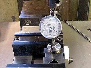
The holes are center drilled and drilled in each collet. The 0.188 hole is just for stress relief and could be omitted as the collet will only be used for one or a few parts. The other hole on one was drilled and reamed to 0.250 to hold the rear half of the center crankshaft (3-3). On the other collet, the hole should have been drilled and reamed to 8mm, but i did not have a 8mm reamer, or even an 8mm drill. So I drilled under size with a 5/16 (0.313) drill and then opened the hole up with a letter "O" drill which is about 0.001 oversize. I think that it will work fine, but if I start getting a little bit of chatter when I start turning the crankpin I will just put a slip of thin paper in the hole with the crankshaft to increase the contact area.
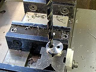
With rods that fit the holes inserted in the holes I shimmed the small rod to make the holes horizontal. A 0.063 shim is needed for the 8mm collet and a 0.031 shim for the 0.250 collet. They are not critical, so any scrap about that thick will work.
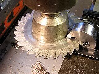
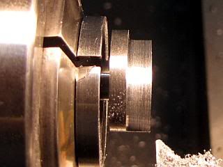
A 0.063 thick by 2.5 inch diameter cutter was positioned over the top of the collet and lowered until a feeler gauge would just fit under it. Never lower the cutter onto the feeler gage as it is easy to damage a cutter. Either lower the cutter until the gauge will not slid under it, or position it low and raise it until the gauge fits.
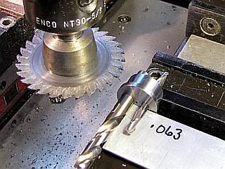
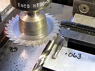
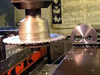
The rods are removed and the cutter positioned to the side. The cutter is lowered to the center line of the collet. This distance will be the thickness of the feeler gauge plus half the diameter of the collet plus half the thickness of the cutter. In this case, 0.025 + 0.500 + 0.031, or 0.556 inch. Position the cutter so the center line is at the back edge of the part. This way the cutter will be conventional milling. Unless you enjoy buying new cutters it is not a good plan to climb mill with this type of setup. I fed to depth and then moved along the axis of the collet to complete the cut.
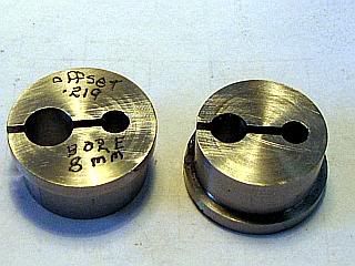
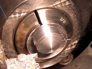
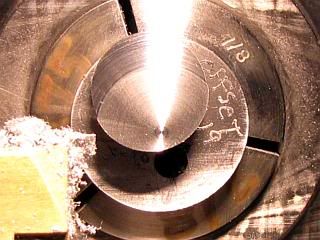
I mark my split collets with the offset and the bore size. I have a box of them and occasionally end up using them for other projects.
Deburr the collets.
Here are the finished collets and the other two fixtures I talked about in the beginning of this post.
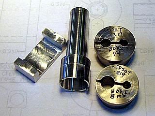
With all this shown, I sometimes just band saw the slot in. Does not look as nice, but works as well.
Gail in NM
On sheet 4 is a simple U channel used to align the crankpins at 180 degrees and the only critical dimension on it is 0.281 depth, so no machining photos are included.
Last,also on sheet 4, is a tool to position the center crankshaft assembly in the crankcase so the 4-40 screw that locks it in place can be inserted. While it is not necessary, it will probably save time and frustration during assembly. Particularly on the third or fourth time I disassemble and reassemble it. No machining instructions are given for it. The 0.188 slot in the side is to allow the connecting rod to pass through and can be about anything you want as long as it is at least 0.188 wide and full depth.
I am detailing the split collets as many machinists have not made or used them. You can get by with out making them and setting everything up in a four jaw chuck, but I like the collets so I make them.
Two blanks are turned up from 1 inch diameter stock on the lathe. The lip is just to keep the split collet from sliding into the lathe collet or chuck. Then it is over to the mill where the blank is held in a vee block in the vice and indicated to locate the center.
The holes are center drilled and drilled in each collet. The 0.188 hole is just for stress relief and could be omitted as the collet will only be used for one or a few parts. The other hole on one was drilled and reamed to 0.250 to hold the rear half of the center crankshaft (3-3). On the other collet, the hole should have been drilled and reamed to 8mm, but i did not have a 8mm reamer, or even an 8mm drill. So I drilled under size with a 5/16 (0.313) drill and then opened the hole up with a letter "O" drill which is about 0.001 oversize. I think that it will work fine, but if I start getting a little bit of chatter when I start turning the crankpin I will just put a slip of thin paper in the hole with the crankshaft to increase the contact area.
With rods that fit the holes inserted in the holes I shimmed the small rod to make the holes horizontal. A 0.063 shim is needed for the 8mm collet and a 0.031 shim for the 0.250 collet. They are not critical, so any scrap about that thick will work.
A 0.063 thick by 2.5 inch diameter cutter was positioned over the top of the collet and lowered until a feeler gauge would just fit under it. Never lower the cutter onto the feeler gage as it is easy to damage a cutter. Either lower the cutter until the gauge will not slid under it, or position it low and raise it until the gauge fits.
The rods are removed and the cutter positioned to the side. The cutter is lowered to the center line of the collet. This distance will be the thickness of the feeler gauge plus half the diameter of the collet plus half the thickness of the cutter. In this case, 0.025 + 0.500 + 0.031, or 0.556 inch. Position the cutter so the center line is at the back edge of the part. This way the cutter will be conventional milling. Unless you enjoy buying new cutters it is not a good plan to climb mill with this type of setup. I fed to depth and then moved along the axis of the collet to complete the cut.
I mark my split collets with the offset and the bore size. I have a box of them and occasionally end up using them for other projects.
Deburr the collets.
Here are the finished collets and the other two fixtures I talked about in the beginning of this post.
With all this shown, I sometimes just band saw the slot in. Does not look as nice, but works as well.
Gail in NM
- Joined
- Feb 17, 2008
- Messages
- 2,330
- Reaction score
- 445
First off, the drawing for the crankshaft assembly jig built in the lat post is wrong. I corrected the drawing before I made the part, so the photo is correct. I will wait until I have made the rest of the parts on sheet 4 before I post the corrected drawing. That way I can correct the other things I probably have messed up.
Next up is the Center Bearing Housing, part 4-2.
I started with 3/4 inch diameter 6061 aluminum. The end is faced and turned to 0.719 for a length of 0.75. The 0.719 diameter is sized to be a close slip fit into the crankcase using the crankcase as a gauge.
Now a 1/2 diameter hole is drilled to a depth of 0.75 to the point. The hole is opened up to 0.531 with a boring bar to a0.68 depth and the end if further opened up to 0.630 diameter for a depth of 0.197 for the bearing. Use a bearing to check for a close slip or light push fit.
The notches are milled in the end of the housing with a 1/16 end mill. Nothing critical about them. They are just to engage the prongs of the center bearing installation tool on sheet 4 so the housing can be rotated in the crankcase to line up the tapped hole.
Using a metal rule or strip of sheet metal, the housing is clamped in the mill vice with the rule inserted into the 0.063 notches and resting on the front jaw of the vice. I pressed it against a vice stop while clamping. Then the housing is center drilled, drilled and tapped 4-40.
After deburring and cleaning the housing, the bearings are started into the housing. A small amount of Loctite is applied to each bearing. I use Loctite 680, and put a drop on my work surface and then use a wire probe to transfer a small amount to each bearing.
The assembly was inserted into the milling vice and the bearings pressed into the housing. It does not take much pressure, but the vice jaws keep the bearing square while they are being pressed into place. The photo shows the bearings above the vice jaws surface, but that was only for photo purposes. The assembly was inserted deep enough in the jaws that the entire surface of teh bearing was in contact with the jaws.
After removing from the vice, any excess Loctite is cleaned off both the assembly and the vice jaws.
Gail in NM
arnoldb
Well-Known Member
- Joined
- Apr 8, 2009
- Messages
- 1,792
- Reaction score
- 12
Gail, thank you for the update 
A question/observation if you don't mind:
Near the start of the post you mentioned that the bearing fit must be close slip/light push, but when you install the bearings using the vice, you say "... the housing. It does take much pressure, but the vice jaws keep the bearing square while they are being pressed into place."
Is this a spelling mistake or did I drop off the wagon somewhere ?
Once again, thank you for this thread; I'm enjoying it very much.
Kind regards, Arnold
- Joined
- Feb 17, 2008
- Messages
- 2,330
- Reaction score
- 445
Thanks Arnold,
I am glad you are enjoying the thread.
The post was in error. It should have read "it does NOT take much pressure...". I have corrected the post.
Never hesitate to ask questions or make comments. I make more than my share of errors. Corrections are the order of the day. So far, every drawing that I have built a part from on this project has at least one correction. Most have been minor. Some have been of the "You idiot, what were you thinking" class, and some to make the part easier to build. Input, like yours, is very valuable. When I am making a part, I know what I intended to draw, so that is the way I make the part. But, it may not be clear to anyone who might try to follow along.
I once had a fellow engineer who sent a drawing out to the shop to have a prototype part made. About an hour later the drawing came back with an envelope full of chips. He had dimensioned a hole larger than the part.
Gail in NM


$24.99
$34.99
Bowl Sander Tool Kit w/Dual Bearing Head & Hardwood Handle | 42PC Wood Sander Set | 2" Hook & Loop Sanding Disc Sandpaper Assortment | 1/4" Mandrel Bowl Sander for Woodturning | Wood Lathe Tools
Peachtree Woodworking Supply Inc

$24.99
$27.99
HOZLY 5PCS/Lot ISO30 Tool Holder Clamp Flame Proof Rubber Claw CNC Machines Automatic Tool Changer
HOZLY


$40.02
$49.99
Becker CAD 12 3D - professional CAD software for 2D + 3D design and modelling - for 3 PCs - 100% compatible with AutoCAD
momox Shop

$99.99
AHS Outdoor Wood Boiler Yearly Maintenance Kit with Water Treatment - ProTech 300 & Test Kit
Alternative Heating & Supplies


$12.56
$39.95
Complete Plans for Building Horse Barns Big and Small(3rd Edition)
ThriftBooks-Atlanta

$39.99
$49.99
Sunnytech Low Temperature Stirling Engine Motor Steam Heat Education Model Toy Kit For mechanical skills (LT001)
stirlingtechonline


$89.99
Outdoor Wood Boiler Water Treatment Rust Inhibitor- AmTech 300 & Test Kit
Alternative Heating & Supplies

![MeshMagic 3D Free 3D Modeling Software [Download]](https://m.media-amazon.com/images/I/B1U+p8ewjGS._SL500_.png)
![DreamPlan Home Design and Landscaping Software Free for Windows [PC Download]](https://m.media-amazon.com/images/I/51kvZH2dVLL._SL500_.jpg)
$0.00
DreamPlan Home Design and Landscaping Software Free for Windows [PC Download]
Amazon.com Services LLC


$519.19
$699.00
FoxAlien Masuter Pro CNC Router Machine, Upgraded 3-Axis Engraving All-Metal Milling Machine for Wood Acrylic MDF Nylon Carving Cutting
FoxAlien Official


$29.95
Competition Engine Building: Advanced Engine Design and Assembly Techniques (Pro Series)
Amazon.com Services LLC


$94.99
$109.99
AHS Woodmaster 4400 Maintenance Kit for Outdoor Wood Boiler Treatment
Alternative Heating & Supplies

arnoldb
Well-Known Member
- Joined
- Apr 8, 2009
- Messages
- 1,792
- Reaction score
- 12
Thank you Gail ;D
Regards, Arnold
Rof}I once had a fellow engineer who sent a drawing out to the shop to have a prototype part made. About an hour later the drawing came back with an envelope full of chips. He had dimensioned a hole larger than the part.
Regards, Arnold
Krown Kustoms
Well-Known Member
- Joined
- Aug 6, 2009
- Messages
- 313
- Reaction score
- 2
looking good
I know I dont have to go far for a laugh. :big:
If I went by my plans Some of my parts would be all chips.
-B-
I know I dont have to go far for a laugh. :big:
If I went by my plans Some of my parts would be all chips.
-B-
- Joined
- Feb 17, 2008
- Messages
- 2,330
- Reaction score
- 445
Yesterday was supposed to be a LOBO building day. I had allocated 6 hours in the shop, and except for an hour to do a simple repair on a steam engine for someone else it was supposed to be all for the LOBO. As it turned out, someone else had "repaired" the engine before me and instead of turn and install one bushing, the engine had to be torn down twice to take care of all the damage. Seven hours into my six hour allotment of time it was all finished. Feeling severely abused, I ordered in dinner instead of cooking and then made up the blanks for the center crankshaft while waiting for delivery.
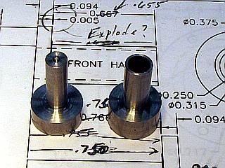
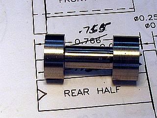
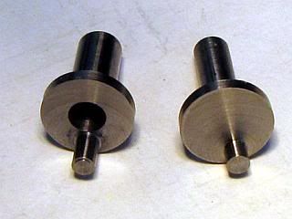
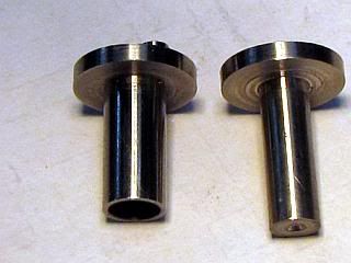
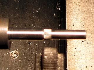
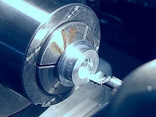
The center crankshaft is made of two parts, 3-2 and 3-3. After machining, they telescope together. One from each end of the center bearing assembly. They are Loctited to each other to form one piece. The blanks are simple turning jobs and one of them is drilled and reamed. The other is only center drilled. The only dimension that is critical at this point is the 0.315 diameter of 3-2. It is to fit the 8mm ID of the bearing, and should be tested with the bearing to be a close fit. Hard to see in the photos, but there is a 0.375 diameter 0.005 step next to the crankdisk to keep the crankdisk from rubbing the outer race of the bearings.
The center hole in 3-3 is not used and in only there to facilitate disassemble of the center crankshaft/bearing assembly in a later life of the engine should it ever be necessary. The hand written dimension in the background drawing are because I changed my mind on how everything will be assembled, and will be changed on the updated drawings. Either set of dimensions would work, the updated ones will just be a little bit neater.
Gail in NM
- Joined
- Feb 17, 2008
- Messages
- 2,330
- Reaction score
- 445
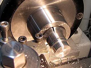
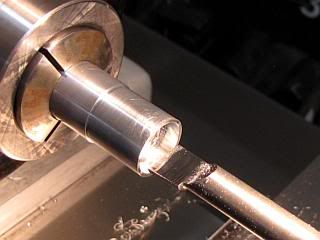
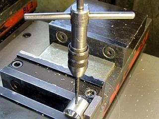
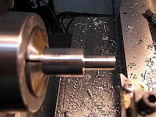
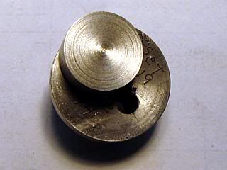
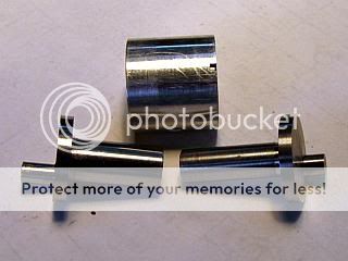
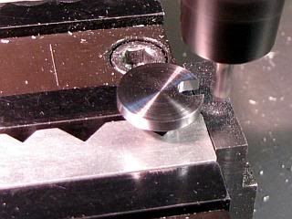
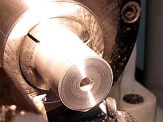
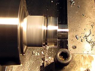
With the center crankshaft blanks done it is time to do something a little bit more exciting, turn the crank pins. The only cardinal rule is the same one that is used anytime that off center work is being done. Never run the lathe under power until you have turned it over at least one rotation by hand. If we follow that rule it will save a lot of excitement.
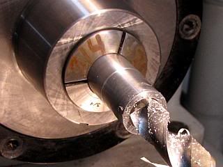
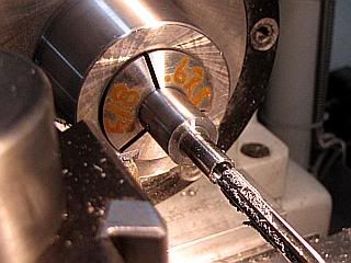
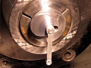
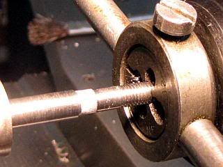
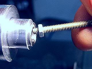
First a blank is inserted into the split collet. If the split collet was made from any kind of cold rolled steel other than 1144 stressproof, then it probably closed up some when it was split. This is the natural action when the stresses are relieved on cold rolled steels. To insert the blank, it will be necessary to insert a wedge into the split to open up the collet. These wedges are more commonly known as flat blade screwdrivers. I like to leave a little space between the part and the collet to make it easier to measure the part with calipers while it is being held in the collet. The split collet is gripped in the lathe. If I am using a collet in the lathe to grip the split collet, the split on the split collet is lined up with one of the splits on the lathe collet. If gripping with a 3 or 4 jaw chuck, the split is positioned between two of the jaws. This is easily visible in the fourth photo.
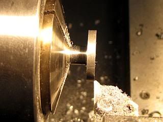
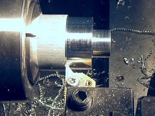
After turning the lathe over by hand, the part is faced off to a thickness of the crank disk plus the length of the crank pin. The crankpin is then rough turned to about 0.010 oversize. I use a VBMT carbide insert with a 0.015 tip radius. I started out at about 1000 RPM and can take 0.050 depth of cut (0.100 on the diameter) with a slow feed on the lathe carriage. My lathe is quite rigid so it may be necessary to reduce this depth of cut on a light lathe. I cut the pin short by about 0.002 on these passes. My insert is set so the side cutting angle is at -2 degrees so the cutting edge angles away from the part.
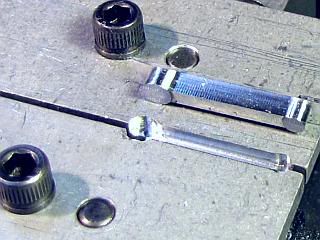
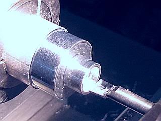
After measuring the pin diameter, I cut one half of the remaining stock one the pin using the same tool. Measuring again, I cut the remaining pin diameter away and continue the cut to the finished length of the crank pin. Then I retract the tool to face off the crank disk. At this point the connecting rod should just fit on the crank pin, but be a little bit stiff to turn. Then I use a parting tool with a square tip to clean out the radius left by the turning tool. I mark the radius to be cut out and the adjoining section of the crank pin with a permanent marker and then machine by inspection until the marker just starts to disappear on the shaft. I polish the crank pin with 600 grit abrasive paper supported by my 6 inch machinist rule. If the paper is flexible enough, it is easier to wrap the paper around the edge of the rule rather than to try to support the edge of the paper with the rule. After polishing, the connecting rod should just be able to hang like a pendulum from the crank pin under it's own weight.
Second verse - same as the first. Just use the other split collet and change the length of the crank pin.
Gail in NM
First a blank is inserted into the split collet. If the split collet was made from any kind of cold rolled steel other than 1144 stressproof, then it probably closed up some when it was split. This is the natural action when the stresses are relieved on cold rolled steels. To insert the blank, it will be necessary to insert a wedge into the split to open up the collet. These wedges are more commonly known as flat blade screwdrivers. I like to leave a little space between the part and the collet to make it easier to measure the part with calipers while it is being held in the collet. The split collet is gripped in the lathe. If I am using a collet in the lathe to grip the split collet, the split on the split collet is lined up with one of the splits on the lathe collet. If gripping with a 3 or 4 jaw chuck, the split is positioned between two of the jaws. This is easily visible in the fourth photo.
After turning the lathe over by hand, the part is faced off to a thickness of the crank disk plus the length of the crank pin. The crankpin is then rough turned to about 0.010 oversize. I use a VBMT carbide insert with a 0.015 tip radius. I started out at about 1000 RPM and can take 0.050 depth of cut (0.100 on the diameter) with a slow feed on the lathe carriage. My lathe is quite rigid so it may be necessary to reduce this depth of cut on a light lathe. I cut the pin short by about 0.002 on these passes. My insert is set so the side cutting angle is at -2 degrees so the cutting edge angles away from the part.
After measuring the pin diameter, I cut one half of the remaining stock one the pin using the same tool. Measuring again, I cut the remaining pin diameter away and continue the cut to the finished length of the crank pin. Then I retract the tool to face off the crank disk. At this point the connecting rod should just fit on the crank pin, but be a little bit stiff to turn. Then I use a parting tool with a square tip to clean out the radius left by the turning tool. I mark the radius to be cut out and the adjoining section of the crank pin with a permanent marker and then machine by inspection until the marker just starts to disappear on the shaft. I polish the crank pin with 600 grit abrasive paper supported by my 6 inch machinist rule. If the paper is flexible enough, it is easier to wrap the paper around the edge of the rule rather than to try to support the edge of the paper with the rule. After polishing, the connecting rod should just be able to hang like a pendulum from the crank pin under it's own weight.
Second verse - same as the first. Just use the other split collet and change the length of the crank pin.
Gail in NM
- Joined
- Feb 17, 2008
- Messages
- 2,330
- Reaction score
- 445
Thanks again for following along, Arnold and Bob.
At this point I test fitted the center crankshafts into the center bearing housing. The points to look for were that everything turned smoothly and that the rear center crankshaft did not protrude through the front center crankshaft. It should be slightly recessed or worst case be flush.
Since all looked OK I inserted the mess into the crankcase from the rear and installed a connecting rod on the front, then slid the assembly forward and put on the other connecting rod. I approximately centered the assembly and rotated the rear crankshaft to top dead center. Then I engaged the crankshaft installation tool with the bearing housing and rotated it until the screw hole in the housing lined up with the hole in the crankcase. A visual inspection showed that the rods were centered in the cylinder bores and that at top dead center there was enough clearance to insert the piston wrist pin. So at least I don't have any major busts on dimensioning. No photos of all this as most everything takes place inside the crankcase where it is hard to see and near impossible to photograph.
The next post will be the assembly of the center crankshaft assembly and have photos of it.
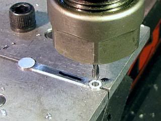
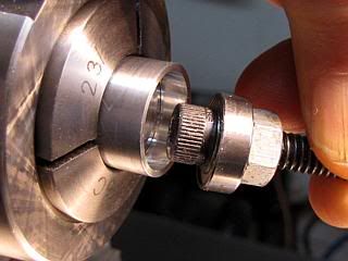
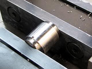
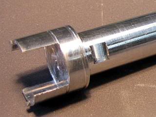
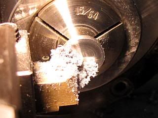
One small problem did show up. The Crankshaft installation tool worked, but it would have been much easier if the slot for the connecting rod were wider and on both sides. So the slot was changed from 3/16 to 7/16 wide and a second slot put on the other side. I also milled a small flat on the handle so I had a reference as to where the rotation was without having to look down into the cylinder bore. A swipe with a permanent marker would have worked as well, but I was already working on the tool in the mill.
I have updated tha master, but have not published it yet. I hope to publish all the current updates by next weekend.
This is how the business end of the tool looks now.
Gail in NM
At this point I test fitted the center crankshafts into the center bearing housing. The points to look for were that everything turned smoothly and that the rear center crankshaft did not protrude through the front center crankshaft. It should be slightly recessed or worst case be flush.
Since all looked OK I inserted the mess into the crankcase from the rear and installed a connecting rod on the front, then slid the assembly forward and put on the other connecting rod. I approximately centered the assembly and rotated the rear crankshaft to top dead center. Then I engaged the crankshaft installation tool with the bearing housing and rotated it until the screw hole in the housing lined up with the hole in the crankcase. A visual inspection showed that the rods were centered in the cylinder bores and that at top dead center there was enough clearance to insert the piston wrist pin. So at least I don't have any major busts on dimensioning. No photos of all this as most everything takes place inside the crankcase where it is hard to see and near impossible to photograph.
The next post will be the assembly of the center crankshaft assembly and have photos of it.
One small problem did show up. The Crankshaft installation tool worked, but it would have been much easier if the slot for the connecting rod were wider and on both sides. So the slot was changed from 3/16 to 7/16 wide and a second slot put on the other side. I also milled a small flat on the handle so I had a reference as to where the rotation was without having to look down into the cylinder bore. A swipe with a permanent marker would have worked as well, but I was already working on the tool in the mill.
I have updated tha master, but have not published it yet. I hope to publish all the current updates by next weekend.
This is how the business end of the tool looks now.
Gail in NM
- Joined
- Feb 17, 2008
- Messages
- 2,330
- Reaction score
- 445
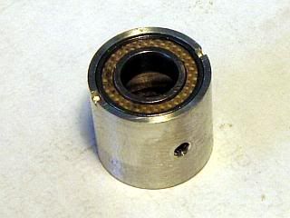
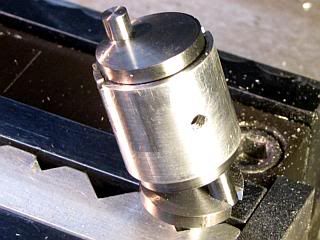
Assembly of the center crankshaft assembly.
First a word about the use of Loctite to hold things together. Generally I make it a rule not to Loctite any parts together that might have to be disassembled later. This part only half violates this rule. The assembly can be dissasembled using heat as the Loctite gives up it's strength at 350 degrees F. This much heat will probably destroy the seals and/or grease in the bearings. In any event it won't do them any good. But, I consider this OK as the only reason that I can think of that this assembly would ever need to be disassembled is to replace the bearings. So if I am going to replace them anyway I am not going to worry about damaging them.
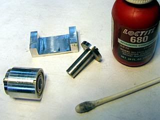
First clean the inside of the front half and the shaft of the rear half with solvent. Acetone or alcohol work fine. Notice the cotton swab in the second photo. Thats what it looked like after cleaning the bore of the front half of the crankshaft.
The front half of the crankshaft is inserted into the bearing assembly. I put it in the side of the bearing assembly that does not have the notches, but it really does not make any difference.
Apply a high strength Loctite, I use 680, to the inside of the front half, being careful not to get any on outside or the bearing. I wiped a small amount of Loctite on shaft of the rear half and wiped all of it off that I could. This is to prime the shaft. I don't know if this does any good, but I do it anyway. The rear half is inserted into the front half with a twisting motion to distribute the Loctite. I hold a paper towel over the far end ot the front half to soak up any excess Loctite as it is forced out. Makes it easer to clean up. Before the rear half is inserted all the way I look to make sure there is no excess Loctite on the shaft that might get squeezed out and into the bearing. If there is any, wipe it off with a swab before seating the two crankshaft halves together.
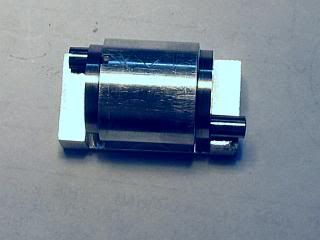
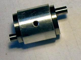
Now place the assembly int he crankshaft assembly jig and press the crankpins down on the flanges while pressing the bearing housing down against the bottom of the notch. At the same time make sure the crankshafts are fully inserted in each other. The crankpins are now at 180 degrees to each other. Take a break while the Loctite cures. After removing from the jig, it will look like the last photo.
Gail in NM
First a word about the use of Loctite to hold things together. Generally I make it a rule not to Loctite any parts together that might have to be disassembled later. This part only half violates this rule. The assembly can be dissasembled using heat as the Loctite gives up it's strength at 350 degrees F. This much heat will probably destroy the seals and/or grease in the bearings. In any event it won't do them any good. But, I consider this OK as the only reason that I can think of that this assembly would ever need to be disassembled is to replace the bearings. So if I am going to replace them anyway I am not going to worry about damaging them.
First clean the inside of the front half and the shaft of the rear half with solvent. Acetone or alcohol work fine. Notice the cotton swab in the second photo. Thats what it looked like after cleaning the bore of the front half of the crankshaft.
The front half of the crankshaft is inserted into the bearing assembly. I put it in the side of the bearing assembly that does not have the notches, but it really does not make any difference.
Apply a high strength Loctite, I use 680, to the inside of the front half, being careful not to get any on outside or the bearing. I wiped a small amount of Loctite on shaft of the rear half and wiped all of it off that I could. This is to prime the shaft. I don't know if this does any good, but I do it anyway. The rear half is inserted into the front half with a twisting motion to distribute the Loctite. I hold a paper towel over the far end ot the front half to soak up any excess Loctite as it is forced out. Makes it easer to clean up. Before the rear half is inserted all the way I look to make sure there is no excess Loctite on the shaft that might get squeezed out and into the bearing. If there is any, wipe it off with a swab before seating the two crankshaft halves together.
Now place the assembly int he crankshaft assembly jig and press the crankpins down on the flanges while pressing the bearing housing down against the bottom of the notch. At the same time make sure the crankshafts are fully inserted in each other. The crankpins are now at 180 degrees to each other. Take a break while the Loctite cures. After removing from the jig, it will look like the last photo.
Gail in NM
- Joined
- Feb 17, 2008
- Messages
- 2,330
- Reaction score
- 445
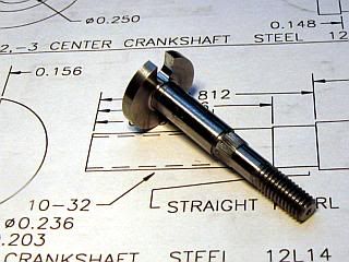
I made the front crankshaft next. If I were building a plain bearing version, I would have made the front bearing housing first and then turned the crankshaft to fit the reamed hole in it.
The Front Crankshaft starts off as a standard turning operation from 5/8 diameter steel bar. The only close tolerance section is the 0.236 diameter that fits the ID of the MR106-2TS bearing. That section should be polished to a close fit on the bearing. The transitions between the 0.203 to the 0.236 diameters and the 0.236 to 0.266 diameters has to be be squared up so the prop driver and a bearing will seat. I used a parting tool with a square tip the same way I did on the center crankshafts. A small center drill is used to create a center in the end of the shaft to facilitate removal of the thrust washer with a gear puller should it ever be needed. A bevel is machined on to the end of the shaft for starting the die to cut the threads.
A straight knurl is used to cut a spline on the 0.203 diameter, raising the diameter to between 0.206 and 0.209. It will depend on what your knurling tool is like. The knurl does not have to reach the shoulder of the 0.236 transition. The 10-32 thread is cut with a die for 14 full turns. With the jaws of my tailstock drill chuck retracted, I use the face of my drill chuck in the tailstock to keep the die square, advancing the drill chuck as I cut the thread.
After parting off with an allowance left to clean up the crankdisk to thickness, the crankshaft is reversed and the crankdisk is faced off to 0.094 thickness.
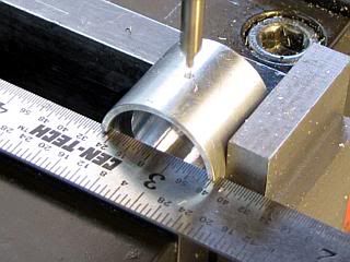
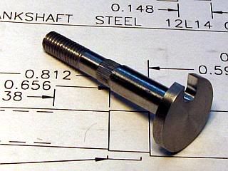
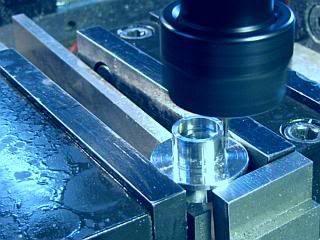
Moving to the milling machine, I put the crankshaft in the vice using a small aluminum vee block that I have made up with different size vee's to for jsut shuch a purpose. It's height is the same as my vice jaw height. The crankshaft needs to be clamped firmly, but not so tight that the hardened vice jaw might put a flat on the crankshaft. I have never had a problem doing this, but if it is a concern, but a piece of aluminum between the hard jaw and the crankshaft.
After indicating the crankshaft to locate the center, the crankshaft slot is milled to be a close fit on the center front half crankshaft crankpin. I used a 5/32 end mill and found that the slot was too tight so I offset the y axis by 0.001 inch and took a second pass. The crankpin then fit the slot smoothly.
After deburring, the front crankshaft looked like this.
Gail in NM
The Front Crankshaft starts off as a standard turning operation from 5/8 diameter steel bar. The only close tolerance section is the 0.236 diameter that fits the ID of the MR106-2TS bearing. That section should be polished to a close fit on the bearing. The transitions between the 0.203 to the 0.236 diameters and the 0.236 to 0.266 diameters has to be be squared up so the prop driver and a bearing will seat. I used a parting tool with a square tip the same way I did on the center crankshafts. A small center drill is used to create a center in the end of the shaft to facilitate removal of the thrust washer with a gear puller should it ever be needed. A bevel is machined on to the end of the shaft for starting the die to cut the threads.
A straight knurl is used to cut a spline on the 0.203 diameter, raising the diameter to between 0.206 and 0.209. It will depend on what your knurling tool is like. The knurl does not have to reach the shoulder of the 0.236 transition. The 10-32 thread is cut with a die for 14 full turns. With the jaws of my tailstock drill chuck retracted, I use the face of my drill chuck in the tailstock to keep the die square, advancing the drill chuck as I cut the thread.
After parting off with an allowance left to clean up the crankdisk to thickness, the crankshaft is reversed and the crankdisk is faced off to 0.094 thickness.
Moving to the milling machine, I put the crankshaft in the vice using a small aluminum vee block that I have made up with different size vee's to for jsut shuch a purpose. It's height is the same as my vice jaw height. The crankshaft needs to be clamped firmly, but not so tight that the hardened vice jaw might put a flat on the crankshaft. I have never had a problem doing this, but if it is a concern, but a piece of aluminum between the hard jaw and the crankshaft.
After indicating the crankshaft to locate the center, the crankshaft slot is milled to be a close fit on the center front half crankshaft crankpin. I used a 5/32 end mill and found that the slot was too tight so I offset the y axis by 0.001 inch and took a second pass. The crankpin then fit the slot smoothly.
After deburring, the front crankshaft looked like this.
Gail in NM
- Joined
- Feb 17, 2008
- Messages
- 2,330
- Reaction score
- 445
Thanks for your continued interest and support Arnold.
The Front Bearing Housing carries the two 6 X 10 mm ball bearings that support the crankshaft. It is a straight turning job with the ends bored to fit the bearings and some mounting holes drill in it. The length needs to be fairly close so it will match the front crankshaft.
I started off with a one inch diameter bar of 6061 aluminum, faced it and drilled a 1/4 inch hole 3/4 inch deep. This is just a clearance hole for the 0.239 (6mm) crankshaft, so other than being centered it has no real requirements. Then the 1/2 inch nose diameter and the major diameter were turned.
The end was bored for the ball bearing, using the bearing as a plug gauge. A small bolt with a nut on it that would fit through the ball bearing ID was used to remove the bearing as it was being test fitted.
After parting off with about 0.01 extra length to allow facing, the part was reversed in the lathe and faced off to length. The hole for the second bearing was then bored to size.
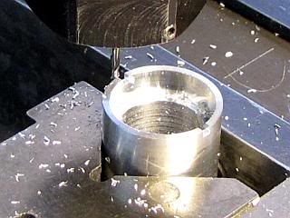
Finally the housing was moved to the milling machine and indicated to zero. The part was supported on parallels for this. Clamping had to be done gently as the vice will deform the outside diameter if clamped firmly. Since the holes were only going to go through the 0.063 flange, I used a 1/16 end mill to drill the holes. This way I did not have to center drill and drill the holes. The holes were drilled using the coordinates on the drawing dialed into the milling machine.
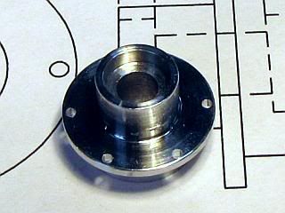
Just a little deburring of the holes and the housing is finished.
Gail in NM
The Front Bearing Housing carries the two 6 X 10 mm ball bearings that support the crankshaft. It is a straight turning job with the ends bored to fit the bearings and some mounting holes drill in it. The length needs to be fairly close so it will match the front crankshaft.
I started off with a one inch diameter bar of 6061 aluminum, faced it and drilled a 1/4 inch hole 3/4 inch deep. This is just a clearance hole for the 0.239 (6mm) crankshaft, so other than being centered it has no real requirements. Then the 1/2 inch nose diameter and the major diameter were turned.
The end was bored for the ball bearing, using the bearing as a plug gauge. A small bolt with a nut on it that would fit through the ball bearing ID was used to remove the bearing as it was being test fitted.
After parting off with about 0.01 extra length to allow facing, the part was reversed in the lathe and faced off to length. The hole for the second bearing was then bored to size.
Finally the housing was moved to the milling machine and indicated to zero. The part was supported on parallels for this. Clamping had to be done gently as the vice will deform the outside diameter if clamped firmly. Since the holes were only going to go through the 0.063 flange, I used a 1/16 end mill to drill the holes. This way I did not have to center drill and drill the holes. The holes were drilled using the coordinates on the drawing dialed into the milling machine.
Just a little deburring of the holes and the housing is finished.
Gail in NM
vlmarshall
Well-Known Member
- Joined
- Dec 28, 2008
- Messages
- 1,138
- Reaction score
- 1
Great work! I'm always glad to click on this thread when I see a new update. ;D
zeeprogrammer
Well-Known Member
- Joined
- Mar 14, 2009
- Messages
- 3,362
- Reaction score
- 13
I've been in such awe...I haven't been able to say anything.
Still can't come up with something to say.
Very interesting thread...well more than interesting...I'm learning a lot here.
Thanks Gail.
Gosh I hope I can make such good stuff someday.
Still can't come up with something to say.
Very interesting thread...well more than interesting...I'm learning a lot here.
Thanks Gail.
Gosh I hope I can make such good stuff someday.
- Joined
- Feb 17, 2008
- Messages
- 2,330
- Reaction score
- 445
Vernon,
I am glad that you are following along.
Zee,
Thank you for your kind comments.
I have been following your progress ever since you first started posting on HMEM. You have come along way since then. The only difference between you and me is that I have made a lot more mistakes (and scrap) than you have. I started hobby machining young and well before the internet. So, my beginner mistakes were private as I did not know any other hobby machinists. You make your mistakes public, and thanks to your sharing them you get immediate feedback as to what others think you might have done incorrectly. But ultimately, the way you learn is to keep at a part until you get one that works for you. Then move on to the next part. Because you share your experiences, many others learn from you. I sometimes get caught up in the number of replies to my posts, but it is worth noting that there are about 30 to 40 times as many views on a thread as there are replies. And, most of the time, there are as many guests as members viewing a thread and online in the forum.
Gail in NM
Similar threads
- Replies
- 7
- Views
- 3K
- Replies
- 1
- Views
- 2K
- Replies
- 7
- Views
- 3K