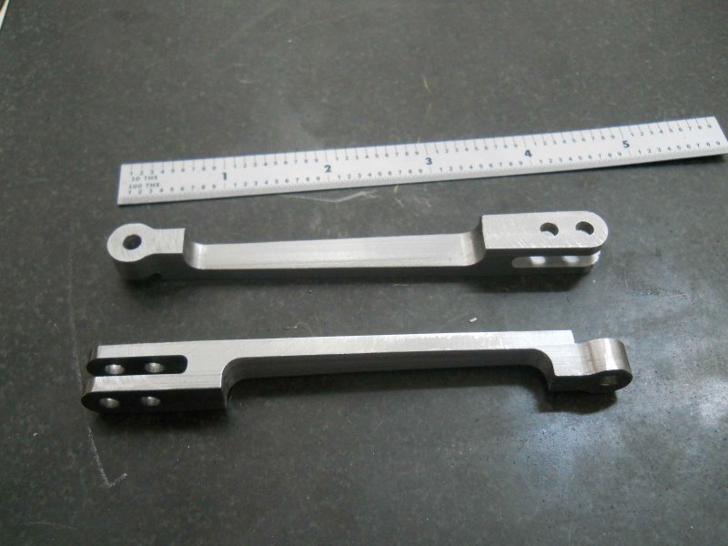
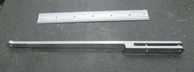
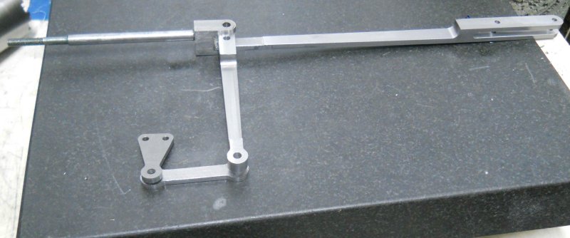
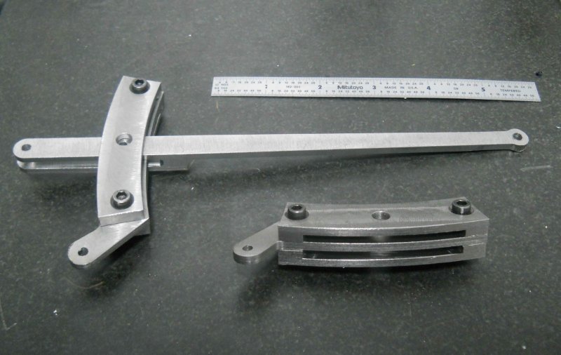
Today I took 5+ hours to get the first crosshead guide in place. As a novice builder, I struggle with knowing where fit and tolerances are important. But since I've had problems on stationary engines with crosshead guides, I decided to see how tight I could get.
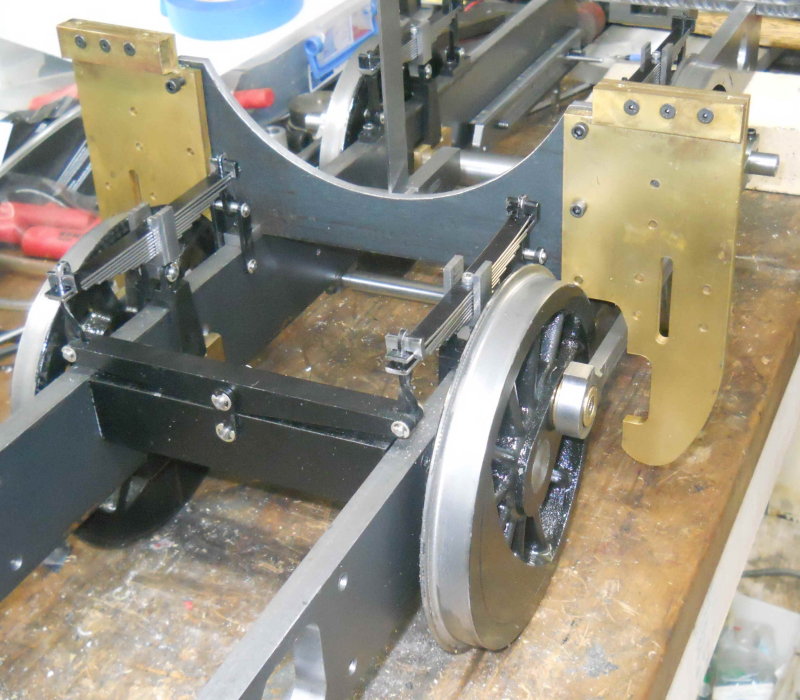
Kozo shows soldering the yoke mounts and then machining to fit. I wasn't going to do it that way for several reasons, among which is the problem I had already soldering on the yokes where I couldn't get it hot enough. Also, the yoke was going to be modified from plan because of the width/gauge issues, so I prefer to do a fit "in place."
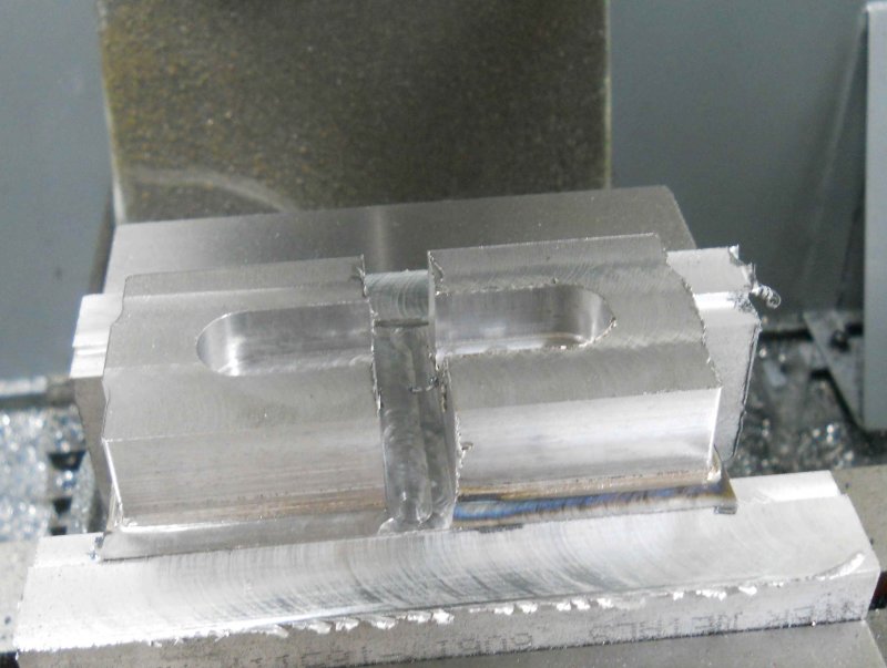
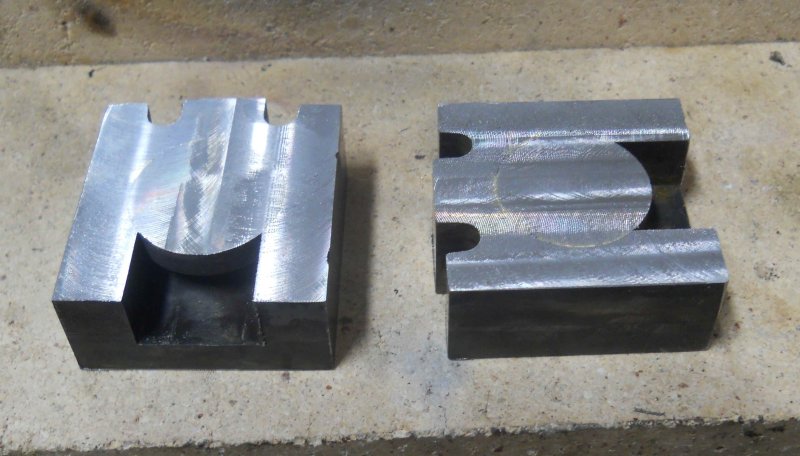
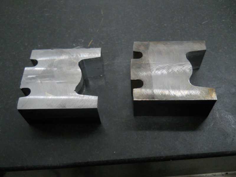
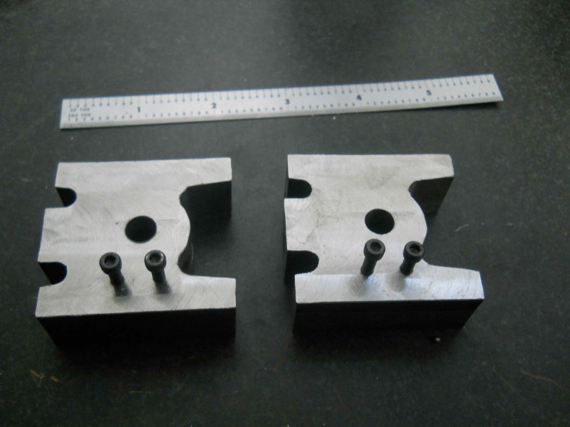
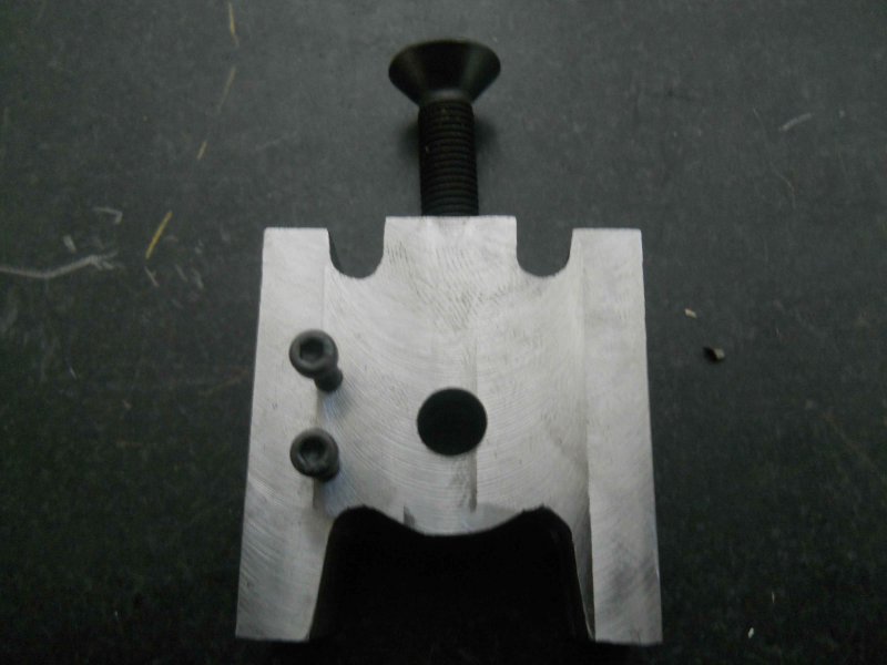
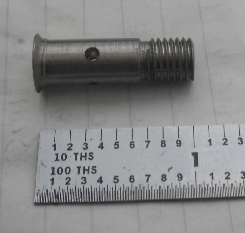
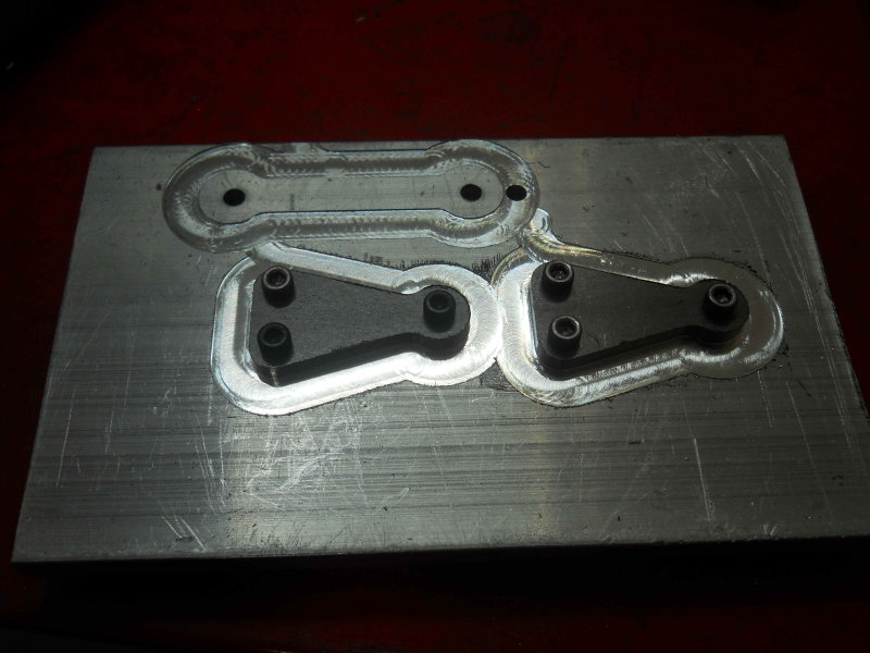
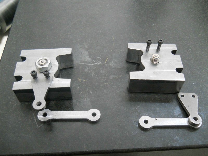
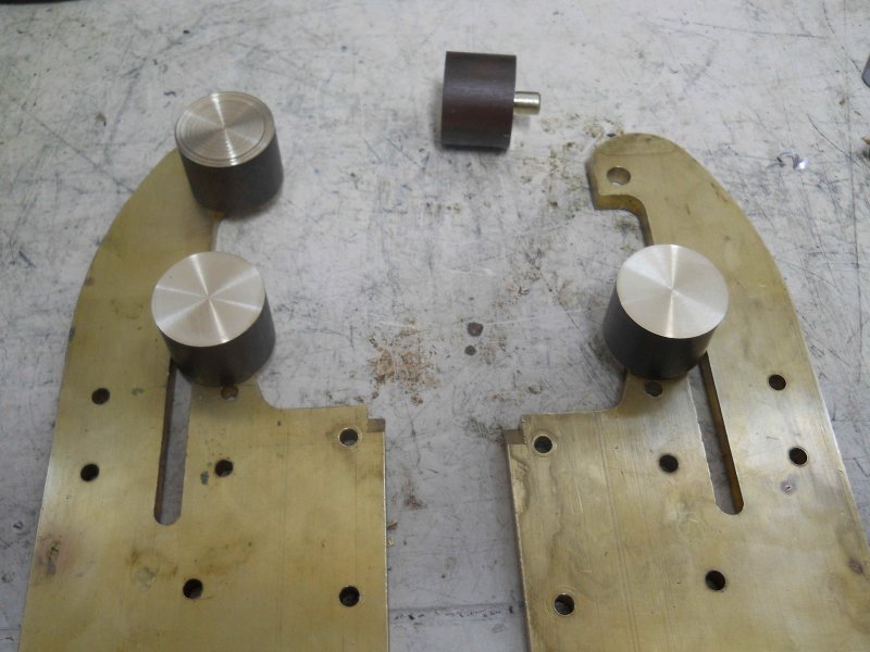
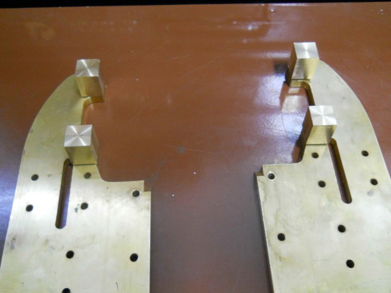
The yokes had 2 1/4" reamed holes for attaching the mounts, so my first task was to machine 4 of these from some 1" round brass stock. The mount body is .75" long, with a 1/4" diameter spigot for attaching to the yokes:
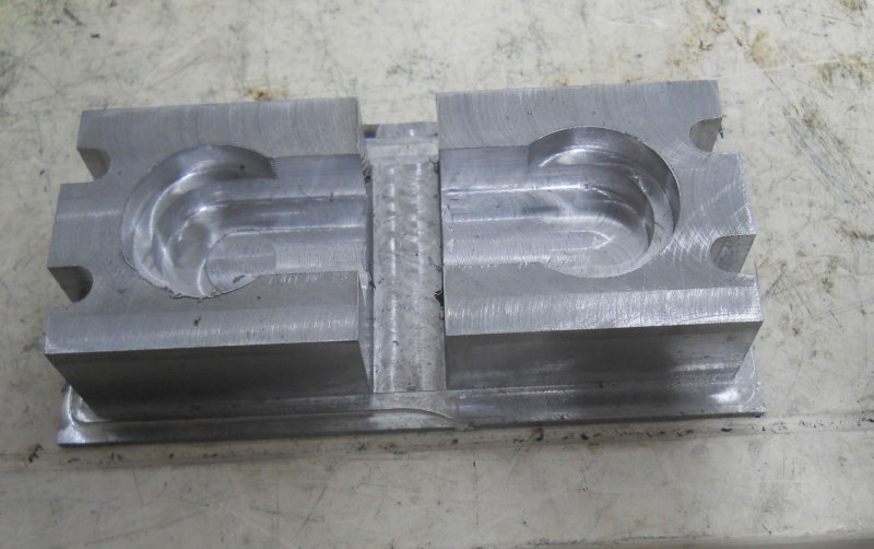
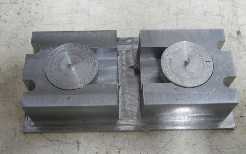
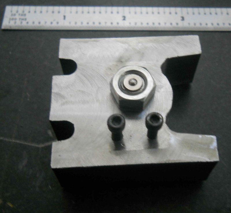
Lots of manual milling later, I have this:
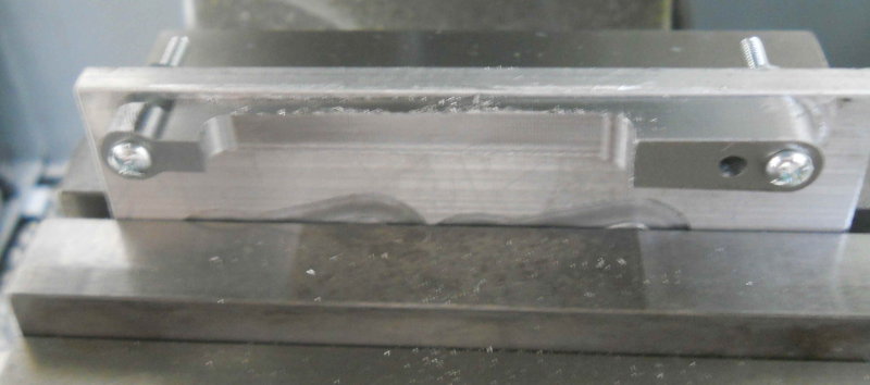
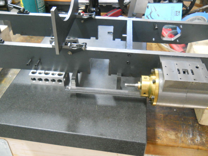
The guides need to be parallel to the frame side as well as the frame bottom. I tried a number of ways to ensure the first parallel to the frame side, but eventually hit on this idea. I knew the distance of the bore centerline from the frame as well as the width of the guide, so I could compute the distance of the inner edge of guide from the frame. I then used gauge blocks to position the bar laterally.
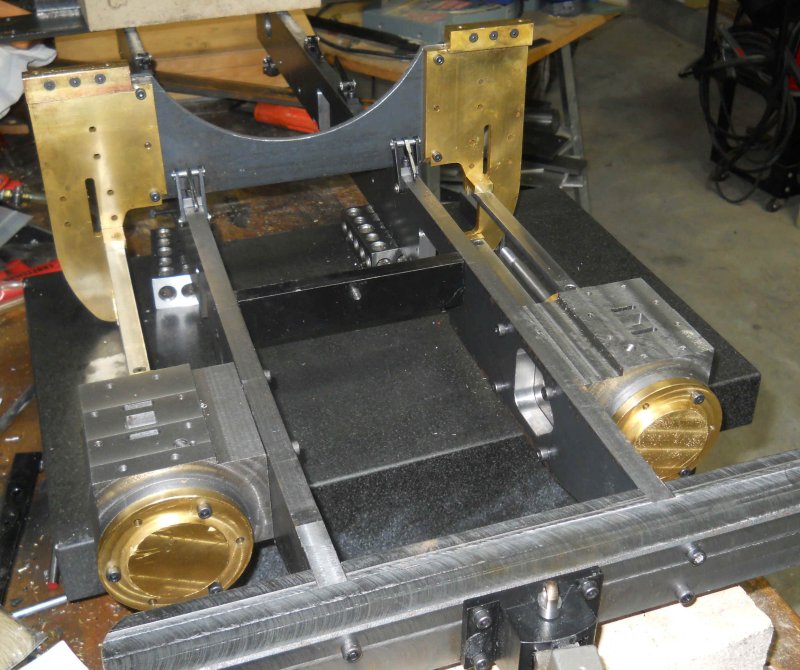
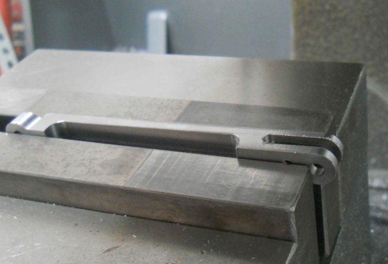
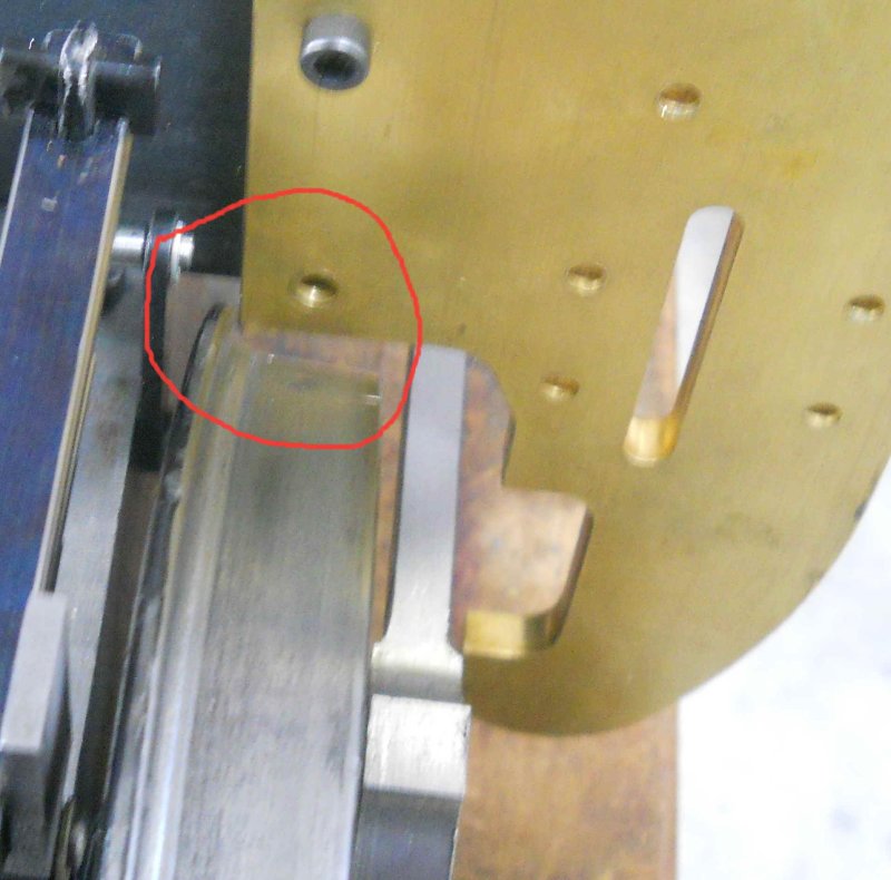
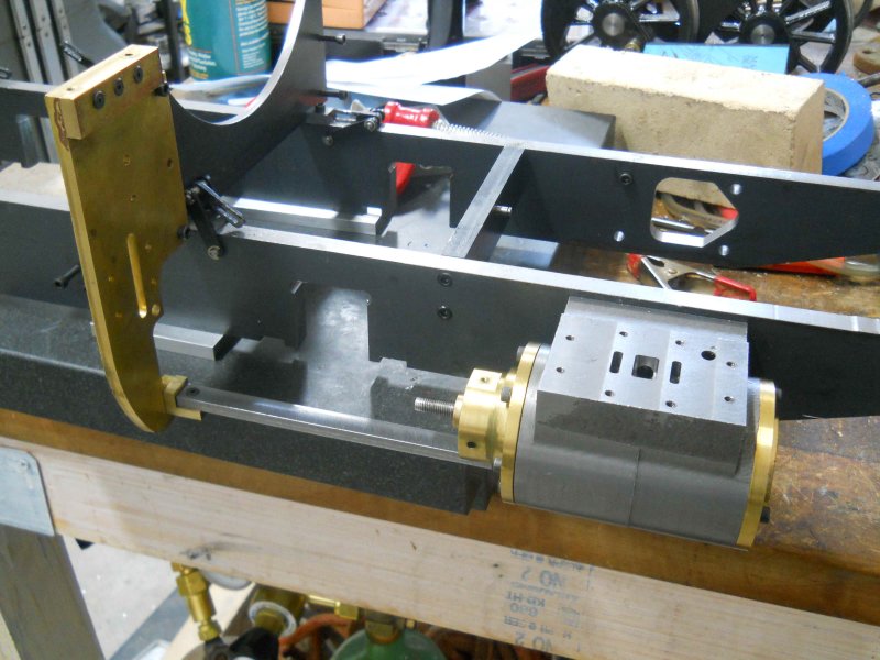
the height gauge gave me the vertical distance at the cylinder end, and also the height of the mount top edge, so now I knew how deep a "notch" to mill in the mount. The final result with the first lower guide in place:
Measurement with a depth mic shows .004" vertical difference between the two ends; I'm satisfied with that result.
The upper bar will be a lot easier since I just need to make it parallel with the lower, via a parallel and some gauge blocks to get the needed measurement to make the upper mount. Even though the guides hold the mounts very tightly against the yokes, I'll loctite them in place.




![DreamPlan Home Design and Landscaping Software Free for Windows [PC Download]](https://m.media-amazon.com/images/I/51kvZH2dVLL._SL500_.jpg)




![MeshMagic 3D Free 3D Modeling Software [Download]](https://m.media-amazon.com/images/I/B1U+p8ewjGS._SL500_.png)


![TurboCAD 2020 Designer [PC Download]](https://m.media-amazon.com/images/I/51UKfAHH1LL._SL500_.jpg)


