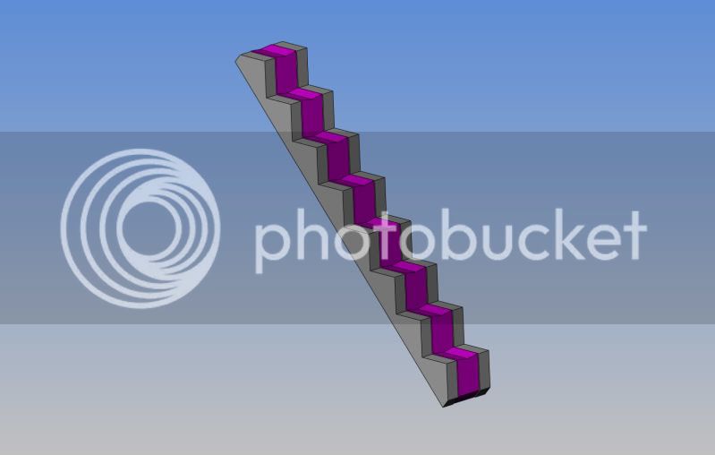
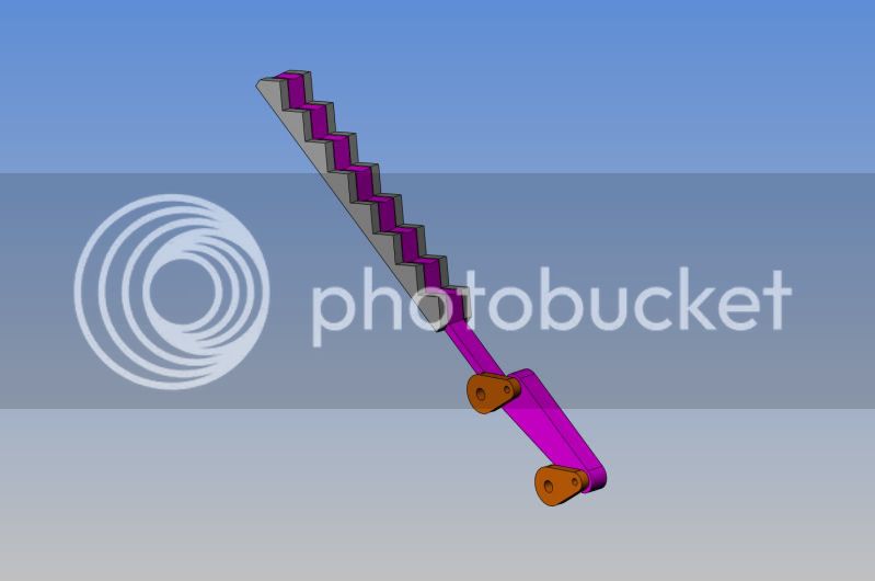
The krazy klockwork machine is finished, and I'm not about to start something new right away, But-----A goodly portion of my 46 years in design engineering has been spent designing material handling projects. One of the more intriguing elevator type devices, to elevate either round rod or pipe sideways out of a full bin and to "singulate" them is called a "Jacobs Ladder". It works on the principal of a moving staircase. Imagine, if you will, 3 very very narrow flights of stairs, on which the treads tip in a bit towards the staircase, while the risers are vertical. In this case, say the outer two flights of stairs were cut from 1/4" plate, the inner flight cut from 1/2" plate, and all 3 set in very close proximity to each other---maybe .030" to .040" apart. The two outer flights are stationary, while the center flight of stairs "orbits". The orbit carries this center flight up the height of one riser plus perhaps 1/16", and then the orbit causes it to "sink back" between the two outer flights, complete its orbit, and once again rise up between the two outer flights and repeat---over and over again, as in continuosly. The tread area in the center flight would have a slight concavity running along it, put in by a v or ball nosed mill. Now, if a person had a supply of 3/4" or 1" diameter wooden or aluminum balls (I think steel balls would be too heavy)---and if they were "funneled" towards the foot of the stairs---. The moving center flight would pick up a ball, carry it upward, and deposit it on the next higher tread of the two outer flights. On its next orbit, it would move this ball up to the next step, while simultaneously picking up another ball. This would keep happening untill all the treads were full of balls, and they started to fall off the top step---where they would be funneled back to the base to start their journey over again. Wow!!! What a neat piece of animation that would be---especially if the orbiting mechanism was driven by a small steam or gasoline engine. In a "real world" application, for example lifting 48" long pipes out of a bin, there would be a Jacobs Ladder at each end, but for a demo unit using balls, only one ladder would be required.---Surely bears thinking about, doesn't it!!!
You are using an out of date browser. It may not display this or other websites correctly.
You should upgrade or use an alternative browser.
You should upgrade or use an alternative browser.
Jacobs Ladder---
- Thread starter Brian Rupnow
- Start date

Help Support Home Model Engine Machinist Forum:
This site may earn a commission from merchant affiliate
links, including eBay, Amazon, and others.
sounds very cool Brian.
If you really want to go off the deep end, perhaps you could make a steam engine wind up a falling ball clock? :big:
http://www.timeonthenet.com/ball_clocks.html
Cheers
Steve
If you really want to go off the deep end, perhaps you could make a steam engine wind up a falling ball clock? :big:
http://www.timeonthenet.com/ball_clocks.html
Cheers
Steve
I built something similar for feeding shockabsorber rods into a centreless grinder (crib of Cincinnatti original IIRC) consisted of alternating stationary and mobile "stairtreads" each cycle would cause the rods to progress up the staircase and eventually onto a conveyor.
The original was crank driven - this one pneumatic - boring industrial stuff.
Ken

The original was crank driven - this one pneumatic - boring industrial stuff.
Ken


$154.76 ($1.38 / oz)
Replacement Combustion Chamber Kit, Burnham V8 and V8H, 1-6 Sec, 108136-01, 1129
Plumbing Planet

$29.95
Competition Engine Building: Advanced Engine Design and Assembly Techniques (Pro Series)
Amazon.com Services LLC

$99.99
AHS Outdoor Wood Boiler Yearly Maintenance Kit with Water Treatment - ProTech 300 & Test Kit
Alternative Heating & Supplies

$94.99
$109.99
AHS Woodmaster 4400 Maintenance Kit for Outdoor Wood Boiler Treatment
Alternative Heating & Supplies

$188.98
TM NEXDYNAMI RE41157 Water Pump Compatible With/Replacement For/John Deere 6200 7400 6300 6600 6500 6400 7220 7600 7200 RE41157
VIVID MARKET CORPORATION

$426.53
DM14 Engine Build Kit, Metal Engine Build Model Great Metal Material for Engineer for Factory
Easoger Official

$39.99
$49.99
Sunnytech Low Temperature Stirling Engine Motor Steam Heat Education Model Toy Kit For mechanical skills (LT001)
stirlingtechonline

$40.02
$49.99
Becker CAD 12 3D - professional CAD software for 2D + 3D design and modelling - for 3 PCs - 100% compatible with AutoCAD
momox Shop

$649.00
$699.00
FoxAlien Masuter Pro CNC Router Machine, Upgraded 3-Axis Engraving All-Metal Milling Machine for Wood Acrylic MDF Nylon Carving Cutting
FoxAlien Official

$109.99
AmTech300 - Boiler Treatment Professional Strength (Rust Inhibitor For Outdoor Wood Boilers)
Alternative Heating & Supplies
Yes Ken, thats the one. Same principal but with the moving portion orbiting on an eccentric instead of driven by a cylinder.
A teaser---Only had time for this much tonight. Have the mechanism to move the center staircase in mind, and if it works i should be able to animate it and post a video----


- Joined
- Jan 4, 2011
- Messages
- 1,429
- Reaction score
- 397
If I understand you correctly I think you are talking about something similar to a walking beam conveyor except moving vertically instead of horizontally. True?
trueGordon said:If I understand you correctly I think you are talking about something similar to a walking beam conveyor except moving vertically instead of horizontally. True?
This is it, and it works really well, just as I had imagined it would. The two orange colored arms must rotate in tandem to give the desired effect, and though I can drag it around on my model, I can't quite figure out how to mate the two orange arms so that they continuously rotate in tandem. (My software is capable of doing it, its just that I don't know how to do it untill I've talked to my Solidworks service provider. I thought it would be the "Gear Mate" function, but it doesn't want to work for me tonight.) In real life, the two arms would have to be on a pair of sprockets connected with a small roller chain. Once I get the mate thing figured out, I will be able to animate it and make a short video of it operating.


Brian,
To get them to work together just requires a conrod between the two offset parts of the 'cams'. Extend the pins that are attached to the centre stairway, and put the conrod to join the two. Just like drive rods on loco wheels.
But you will need to drive just one from the opposite side the 'cams' are on.
John
That doesn't work John, without some kind of flywheel effect. When the driving wheel passes "over center", the driven wheel wants to stop and rotate backwards.
This is what I like about this site.
Someone is always building something different AND showing now they did it rather than keeping it a secret.
Your Krazy Klockwork Mechanism was as fun to watch run as it was to watch you build, I am sure this will just as great.
My only complaint is I am spending too much time on the computer and not enough time building my own projects. ;D
Thanks Brian!!
John
I understand where you are coming from Brian, but I have seen the method I described used in a few places, and not on 'light' work either.
There are plans about that use that method, instead of gears, for making a set of sheet metal rollers.
As long as centres of the bearing holes for the two shafts are exactly the same as the centrers of the two holes in the conrod, then things should be OK.
John
There are plans about that use that method, instead of gears, for making a set of sheet metal rollers.
As long as centres of the bearing holes for the two shafts are exactly the same as the centrers of the two holes in the conrod, then things should be OK.
John
John---I certainly can't argue with you. A thousand steam trains can't be wrong!!! I just can't get it to work in my software.
Thats why there are two pivot points down at the bottom. That keeps the top of the ladder travelling in a fixed circular path. I could have just as easily put one of the pivots up at the top, but then the balls wouldn't have been able to fall off,archer3d said:Looks like a great mechanism, but I just cant figure out how you will control the top of the moving ladder, Will just have to wait
tom
Similar threads
- Replies
- 77
- Views
- 29K


![MeshMagic 3D Free 3D Modeling Software [Download]](https://m.media-amazon.com/images/I/B1U+p8ewjGS._SL500_.png)


