I finally got my balls back!!!

Home Model Engine Machinist Forum

Help Support Home Model Engine Machinist Forum:

This site may earn a commission from merchant affiliate links, including eBay, Amazon, and others.

Brian Rupnow

Design Engineer
Project of the Month Winner
Joined
May 23, 2008
Messages
15,273
Reaction score
8,560
Location
Barrie, Ontario, Canada
How's that for a catchy title?? I built this 3 ball governor a few years ago when I was attempting to convert my Webster to a hit and miss engine. It worked--"sorta/kinda" but not really well. The governor then set up on a shelf for a few years until I built the Rupnow engine, and I robbed the balls of the governor to use, and had to modify them to fit the governor on the Rupnow Engine, but they were too heavy, so they were swapped out for a different ball. I couldn't put them back on my 3 ball governor because I had drilled out the #5-40 threads that held them to the governor arms. This morning, after finding them languishing in a can of "Odds and ends" I drilled them out for a 0.225" diameter brass rod, Loctited it in place, and redrilled and tapped the #5-40 holes through them. I gave them a bit of a polish and reinstalled them on my governor. I don't currently have a use for the governor, but if I decide to use it on something in the future, at least it is all back together and ready to go----with shiny balls!!!
 
Yes - congrats Brian! And big brass ones are the best kind to have!:D
 
I have thought different times about hooking this governor up to run in conjunction with one of my modern 4 cycle engines. Going thru all the steps in the process last night, I'm not sure if that is possible. A governor works fine with a hit and miss engine, because when the engine speed exceeds the "set point", the governor will engage the mechanism that keeps the exhaust valve off it's seat and cause it to hold the exhaust valve open until the rpm falls below the "set point" whereby the governor will release the mechanism and let the exhaust valve close and the engine will start firing again. The engine can not fire when the exhaust valve is held open. The carburetor on a hit and miss engine has no throttle at all---it is always set to run "full throttle". The strength of the governor arm return springs and the weight of the brass balls and the gearing to the brass balls is what determines where this "set point" is. Thus, the rpm of the engine can be adjusted to the speed you want by adjusting the strength of the springs, the weight of the balls , or the gear ratio which determines how fast the balls spin. The one thing to remember here, is that the action of the governor is not "incremental"---Meaning that it can only stop the engine from firing or let it resume firing, with no intermediate points between the two. Now, if we look at hooking the governor up to the throttle on the carburetor of a conventional 4 cycle i.c. engine, the logical place for a control link would be between the governor arm and the throttle lever. Lets think about this. We take a guess at where our "set point " will be for a desired rpm (say about 2000 rpm). Let us assume that we want to start the engine with it's throttle in a position just above idle speed. Due to the nature of a centrifugal governor, we would have to over-ride the mechanism to get the throttle into this position. The engine starts, we release the over-ride, and the engine revs up to the governors "set point" of 2000 rpm. At that point, the governor balls have flown outward under centrifugal force until the linkage begins to close the engine throttle. If we have the linkages adjusted proportionally, the governor will begin to close the throttle, the engine will begin to lose rpm, and feeling the effect of this, the governor will again cause the engine to speed up to the "set point" rpm. by opening the throttle. So--our conclusion is that the engine can never rev up higher than the "set point". Now let us assume that the engine is driving something that places a load on the engine. If the load comes onto the engine while the engine is running at 2000 rpm, the rpm will then fall off, but the throttle will still be in the same position it held at 2000 rpm under "no load". The governor will then have to open the throttle even wider than it's normal set point to pick the rpm back up to 2000 rpm. If it over revs beyond the 2000 rpm set point the governor should be able to recognize this and back the throttle off. The problem as I see it, is that the governor now has to recognize intermediate throttle positions instead of just "run" or "not run", because under load, the engine rpm is going to drop off from what it would be under "no load' even though the throttle lever remains in exactly the same position. Am I overthinking this? I believe Bob Shore's Silver Angel engine has a centrifugal governor on it, but it may be a hit and miss engine--I don't know.
 
Last edited:
I have just confirmed that the Silver Angel was indeed a hit and miss engine, and that the governor did hold the exhaust valve open during the "miss" cycles. I am interested in knowing if a conventional, throttled engine can be controlled properly by a flyball governor.
 
I would assume it could be, as long as there is enough movement in the linkage to the balls to operate the throttle from fully closed to fully open. As you said, as the balls start to drop from the 'set point' the throttle is opened proportionally and as it revs back up the throttle is proportionally closed.

Although not a flyball governor, an old lawnmower I used to have had a mechanical governor that consisted of the throttle being held wide open with a spring and a small plastic 'sail' was attached to the throttle arm. The flywheel had fan type blades on it that directed air to the little 'sail'. As the engine revs increased, the airflow to the sail increased and forced the throttle to close. As revs dropped the spring would open the throttle back up. A different type but proof a mechanical governor can operate a throttle.
 
Al has a valid point there. The default position for this type of governor is "full throttle" with the engine stopped. As the engine speeds up, the governor starts to close the throttle and, if the stars align correctly, will catch the rising engine speed with a suitable rate of closing throttle so that the engine settles at the desired speed.
As a secondary point, cannot a 4-stroke engine still be governed by holding the exhaust valve open like a hit and miss? Just a thought.

Ian.
 
This is the original video I made to explain the working of this 3 ball governor. Almost the first words out of my mouth were wrong. They weren't found on steam trains, only on industrial stationary steam engines. However, everything else is correct.
[ame]https://www.youtube.com/watch?v=kvk9vQckGJo&feature=youtu.be[/ame]
 
Last edited:
The only thing missing here is an adjustable "counter spring". In it's current form, my governor lacks the "adjustable counter spring" which is required to allow setting the "sweet spot" while the engine is running. There are many ways of mounting this "adjustable counter spring" and what it really does is counteract or add to some of the force on the stempost spring which draws the governor springs back to the centerpost (low rpm condition) after they have flown out under high speed. The strength of that centerpost spring determines at what speed the engine rpm overcomes the centerpost spring to allow centrifugal force to start the balls moving out away from the centerpost and beginning to move the lever.
 
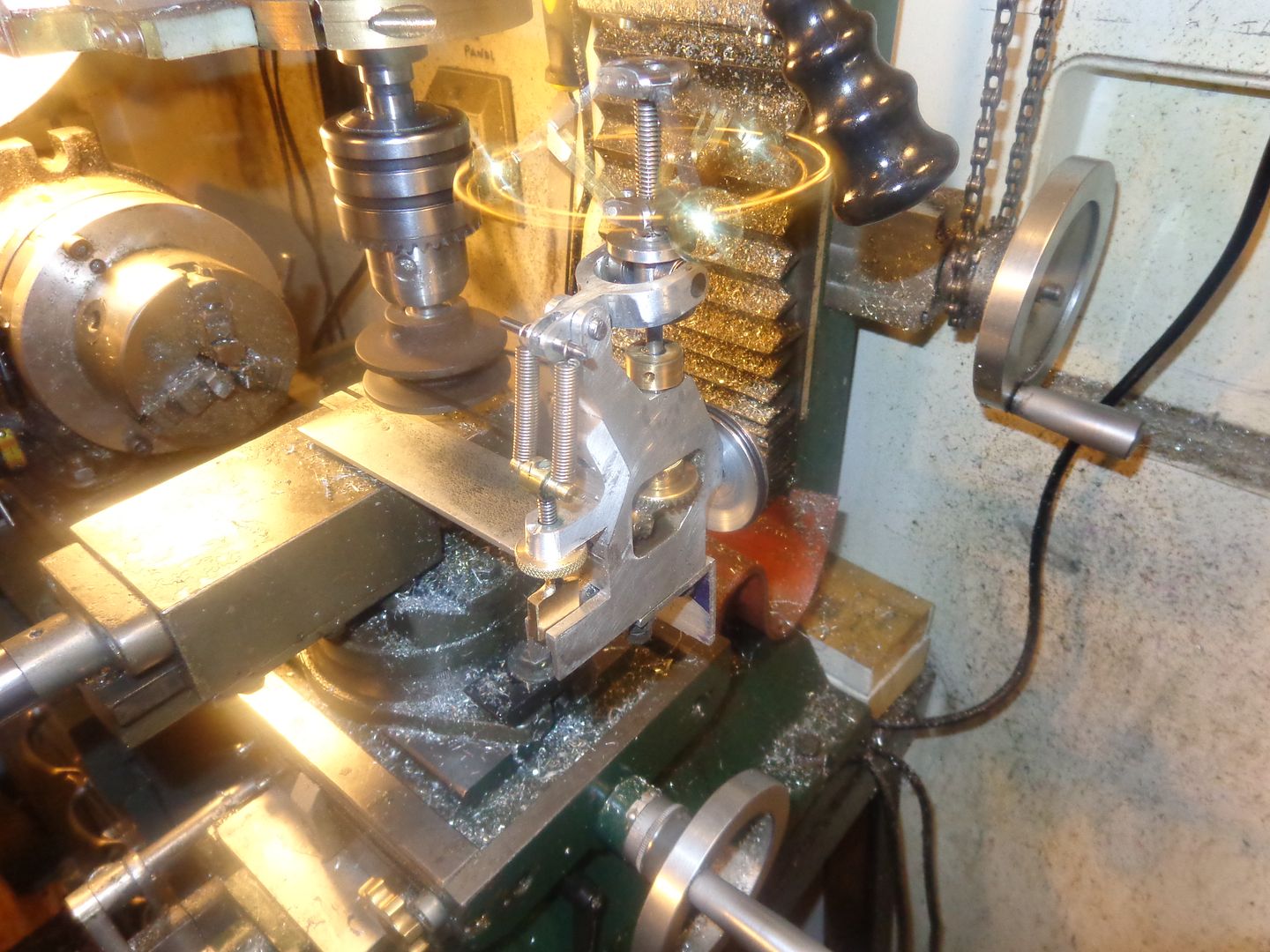
What's going on here?? Well, I'm at the prototyping stage of an adjustable counter spring for this governor--and what I have so far works. The governor in it's original form as seen in the very first post, had a couple of link arms that were redundant--not needed any more. Also, with no means of adjusting the compression spring riding on the center of the stempost, what you got was what you got in terms of when the mechanism activated at a certain rpm. Now in a perfect world, you want to be able to make this adjustment when the machine is actually running, and that is not possible--without the changes I have made. You will see that I have changed the shape of the governor body, removed the redundant links, and added a bracket to the body. A threaded rod passes through a plain hole in the new bracket, with a flat piece of brass soldered to the end of it, and the flat piece of brass fits into a slot in the aluminum body to keep it from rotating. A threaded and knurled "finger wheel" can be turned to move this threaded rod either up or down in the hole. The other end of the threaded rod is cross drilled for a .093" cross pin, and a pair of tension springs run from the cross pin up to the end of the yoke lever. By tightning the knurled finger wheel and forcing the threaded rod down, I can put more tension on the two tension springs. This tension serves to counteract the compression spring on the stempost. This can be done while the governor is actually being driven by whatever machine it is mounted on.---And, since I am effectively changing the force the compression spring exerts on the flyball mechanism, I can change the rpm at which the flyball mechanism activates. It works!!! I can feel the difference in force needed to lift up the governor arms when I tighten the adjuster and put more tension on the tension springs. I have a bit of work to do yet before I make an actual dynamic test, but this is very interesting. I still have no firm plans about mounting this on one of my i.c. engines, but the method for adjusting it does work. I will make a short video to demonstrate this "adjustability" tomorrow.
 
This seems like the perfect time and place to tell my Leonard story once again---
Leanard story
I grew up in the kinder, gentler, far more poverty stricken world of the 1950's. I have a firm belief that it wasn't necessity that was the mother of invention---poverty was. The lack of money created a world of tinkerers and inventors, simply because there was no money to buy the proper tool or machine. An older friend of mine, named Leonard had built a portable buzz saw for cutting firewood. This was basically a 48" diameter circular saw mounted on the chassis of a model A Ford, circa 1930 or 1931. The lengths of wood were lifted onto a tilting carriage, and the carriage was tilted into the saw to cut up lengths of firewood. The saw was driven by a flat belt and pulley arrangement that came from the rear of the old Fords transmission. Now, Leonard had a problem----The old 4 cylinder Ford engine had babbit bearings, so it did not take kindly to prolonged high speed revving. However, if someone didn't open the throttle and give it some gas when the log engaged the saw, the engine would stall. Leonard was a veteran tinkerer, and somehow come into the possession of a set of flyball governors off an old steam engine. He mounted them with a belt drive from the Ford engine, and hooked them up to the carburetor with a system of levers and pulleys. The theory was quite simple---under no load conditions the old Ford would set there idling, but as soon as the log engaged the buzz saw, the rpm's would drop off, and the flyball governors would open the throttle automatically. This was a perfectly good working theory!!! The problem was that Leonard somehow got one of his lever arrangements bass ackwards. When the last bolt was tightened, and the last brace welded in place, Leonard went to test his creation. He started the Ford---that part worked perfect. As soon as it started however, the flyballs began to fly outward from centrifugal force, and the farther out they flew, the more the lever mechanism opened the throttle. The engine went from zero to a zillion rpm's in the blink of an eye. Leonard leaped from the drivers seat and raced around the car to pull off the coil wire and shut down the engine---and at the same time the flyball governor self-destructed (it too was by then doing a zillion rpm's). One of the steel balls flew and hit poor Leonard directly in the kneecap and broke it into a dozen pieces--then the old Ford engine self-destructed in a scream of tortured babbit bearings and shattered castings!! Leonard eventually recovered, though he walked with a limp ever afterwards. We all survived the 1950's, but it certainly was a time that gave rise to a lot of interesting stories.---Brian.
 
No movie today. The "compensator springs" do have a very definite effect on just what rpm the balls will elevate at from centrifugal force (as seen in this picture). However, the effect is not large enough to show well in a video. The brass balls are so heavy that they over-ride the effect. I could achieve what I want to show with even stronger compensator springs, but that would be overstressing the system. I do have a complete set of aluminum balls to try on the governor. I know that they work, because I had them on the governor of the Rupnow Engine during tryouts with it. i will swap them out for the brass balls and see what happens---I believe they will make the effect of the compensator springs much more visible for a video.
 
Hi Brian
the normal way to make a this type of gov variable is to have the spring external and no spring in the centre .in the diagram if you pull the spring tighter it moves the balls down and the engine has to speed up to generate more force to lift the balls .
the three holes in the arm alter the sensitivity of the gov move the spring away from the pivot you get tight governing but to far it will hunt.
towards the pivot it gets soft and requires a wider seed range to control.
a soft spring can be put in line with the main spring to give a good idle ,only pulling the main spring when it reaches a limiting stop. not shown on drawing.

I hope this helps. shout of you want more.

Brian
Sorry forgot to turn it.

img021.jpg
 
Brian
Do you have drawings available for your governor?
Nice standalone project , or scale to fit project.
Thanks! Dale
Here is a download link to my original 2 ball governor that I built and use to control a steam engine I built. I don't seem to have the plans around anymore for the 3 ball governor.
http://www.mediafire.com/download/nw4ryqtqdu5/BRIANS_FLYBALL_GOVERNOR.zip
I hunted around until I found this thread, which gives all the info for making the two ball governor into a 3 ball governor.
http://www.homemodelenginemachinist.com/showthread.php?t=9474
 
Last edited:
Last night, during a horrible case of insomnia, I worked out all of the linkage required between the lever arm on the governor and the throttle lever on a gas engine. The engine best suited to use with this governor, because of the way the carburetor faces and the throttle lever pivots, is my Fat Flywheeled Webster. Due to the physical shape of engine and the governor, (which evolved independently), the governor is going to have to set above the engine. This doesn't create a problem, although it may look a bit strange. I think I will build a 'bridge" over the top of the Webster, which the base of the governor will set on. This should line the pulley groove on the governor up with the pulley groove on the Webster, and put the governor lever more or less directly above the carburetor.
 
This video shows a trial I made about 5 minutes ago to see if the Webster has enough power to spin the flywheel governor.
[ame]https://www.youtube.com/watch?v=BUhM5nUAPqA&feature=youtu.be[/ame]
 
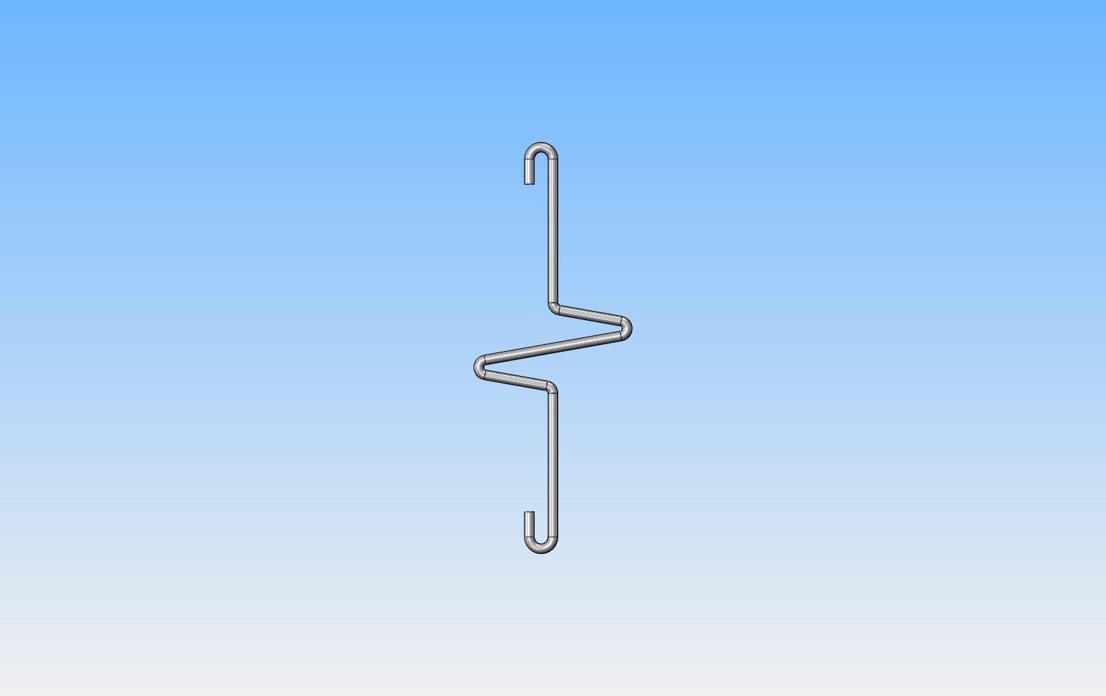
Now I have my thinking cap on. The carburetor throttle handle (which I have yet to build):eek: will be connected to the extension of the governor pivot arm (which I have yet to build.):eek: The governor pivot arm can exert a surprising amount of force, depending on how fast the governor balls are revolving. I will calculate the travel of both the throttle arm and the governor arm so they both travel roughly the same amount---but I don't want to throw a whole bunch of force into my carburetor and break it. So---we build a compensating connector link!! The link will be bent up from 2mm diameter uncoated welding wire. It takes VERY LITTLE force to move the throttle arm through its travel, as long as you don't "bottom it out" at either end of it's swing and then try to force it farther. The rather artisitic bends in the welding wire will let the wire deflect and take up any "over-travel", rather than break my pretty little Chuck Fellows carburetor.-
 
Last edited:
What's going on here?? Well, I'm at the prototyping stage of an adjustable counter spring for this governor--and what I have so far works. The governor in it's original form as seen in the very first post, had a couple of link arms that were redundant--not needed any more. Also, with no means of adjusting the compression spring riding on the center of the stempost, what you got was what you got in terms of when the mechanism activated at a certain rpm. Now in a perfect world, you want to be able to make this adjustment when the machine is actually running, and that is not possible--without the changes I have made. You will see that I have changed the shape of the governor body, removed the redundant links, and added a bracket to the body. A threaded rod passes through a plain hole in the new bracket, with a flat piece of brass soldered to the end of it, and the flat piece of brass fits into a slot in the aluminum body to keep it from rotating. A threaded and knurled "finger wheel" can be turned to move this threaded rod either up or down in the hole. The other end of the threaded rod is cross drilled for a .093" cross pin, and a pair of tension springs run from the cross pin up to the end of the yoke lever. By tightning the knurled finger wheel and forcing the threaded rod down, I can put more tension on the two tension springs. This tension serves to counteract the compression spring on the stempost. This can be done while the governor is actually being driven by whatever machine it is mounted on.---And, since I am effectively changing the force the compression spring exerts on the flyball mechanism, I can change the rpm at which the flyball mechanism activates. It works!!! I can feel the difference in force needed to lift up the governor arms when I tighten the adjuster and put more tension on the tension springs. I have a bit of work to do yet before I make an actual dynamic test, but this is very interesting. I still have no firm plans about mounting this on one of my i.c. engines, but the method for adjusting it does work. I will make a short video to demonstrate this "adjustability" tomorrow.
good to see u got your balls back
 

Latest posts

Back
Top