Horizontal Air Cooled Engine

Home Model Engine Machinist Forum

Help Support Home Model Engine Machinist Forum:

This site may earn a commission from merchant affiliate links, including eBay, Amazon, and others.
I have always used Brownell anti oxide paste. Others seem to get by without it just fine. I am not sure if I am doing something good or just wasting time and money.

I have always used some good quality end cutters to cleave the rings which should work like Trimble's cleaver. When I end up with a bad ring it is usually right at the break but I am not sure if making his cleaver would improve results. Brian did not have much luck with his. Trimble said that he had trouble making good rings until he made his. Anyone have any thoughts?
 
Last edited:
The rings are on the piston and the piston is back in the engine, and everything goes round and round and up and down like it's supposed to. Out of 8 rings four were damaged, two are on the engine, and I have two left over for some other project.---I would not recommend putting new rings on a new piston to anyone who was looking for a way to pass a tranquil afternoon. There is no cylinder head on the engine right now, but it does have lots of "suck" when I put my hand over the cylinder and turn the engine over with the flywheels.----thats a good thing!!!!
 
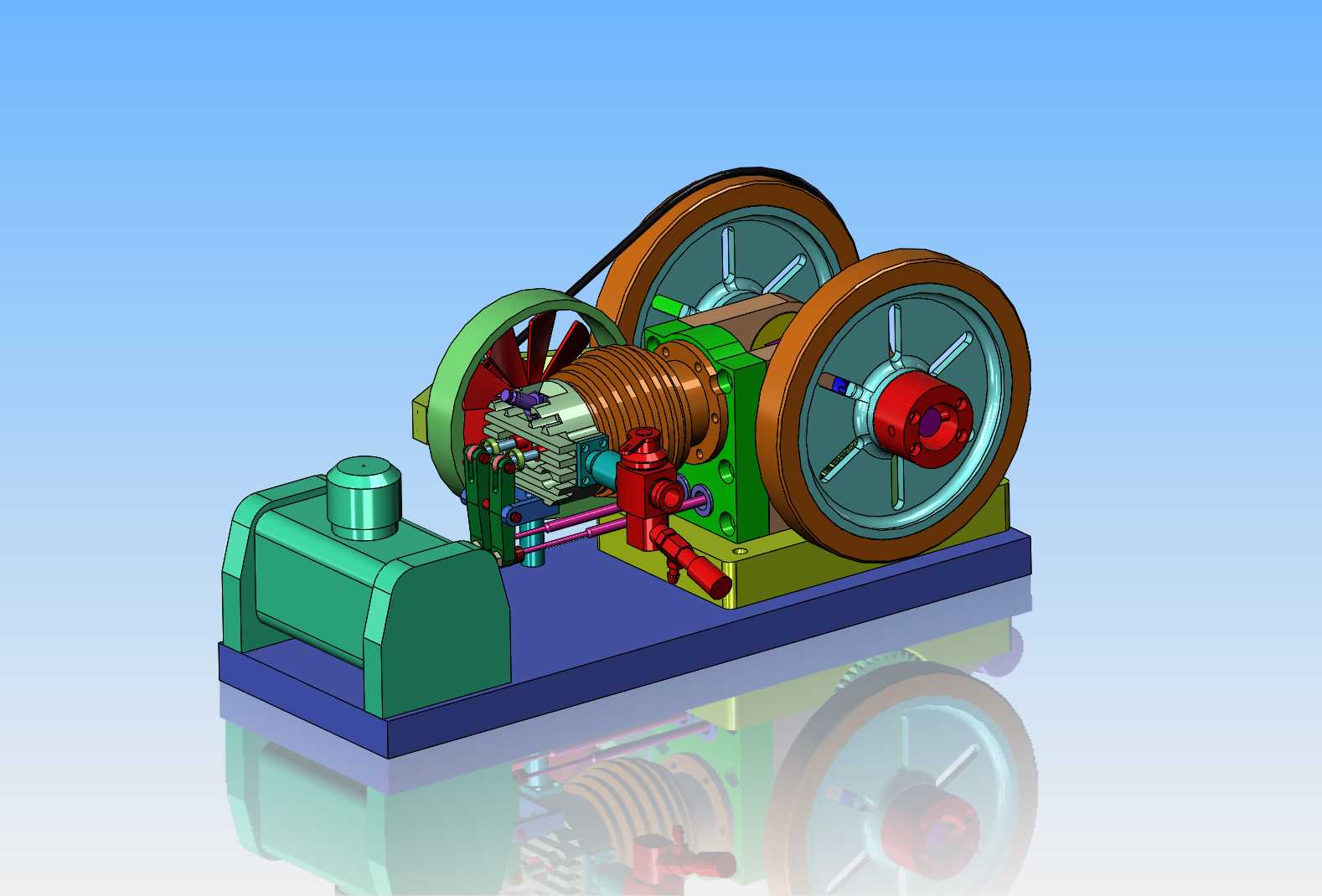
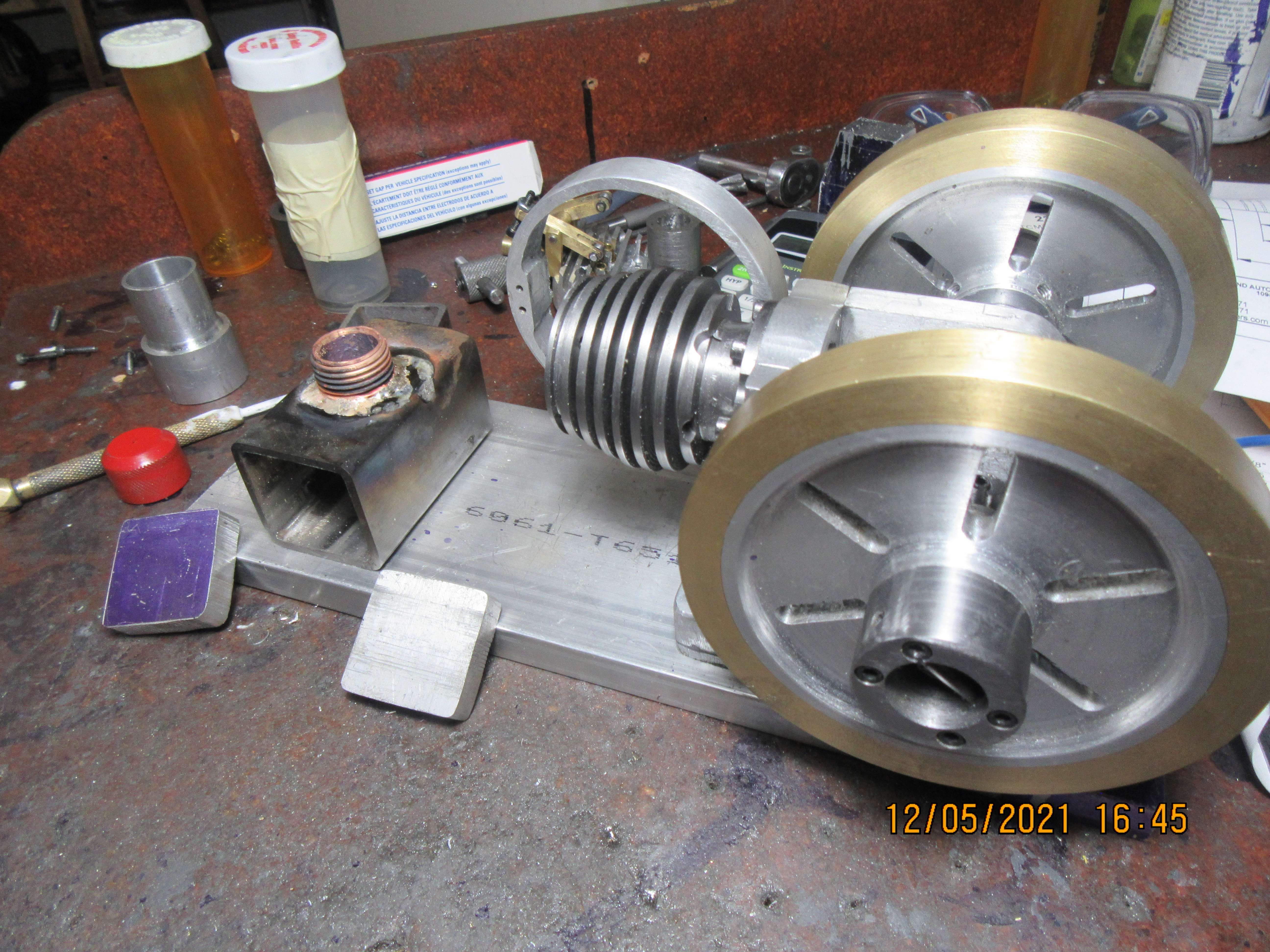
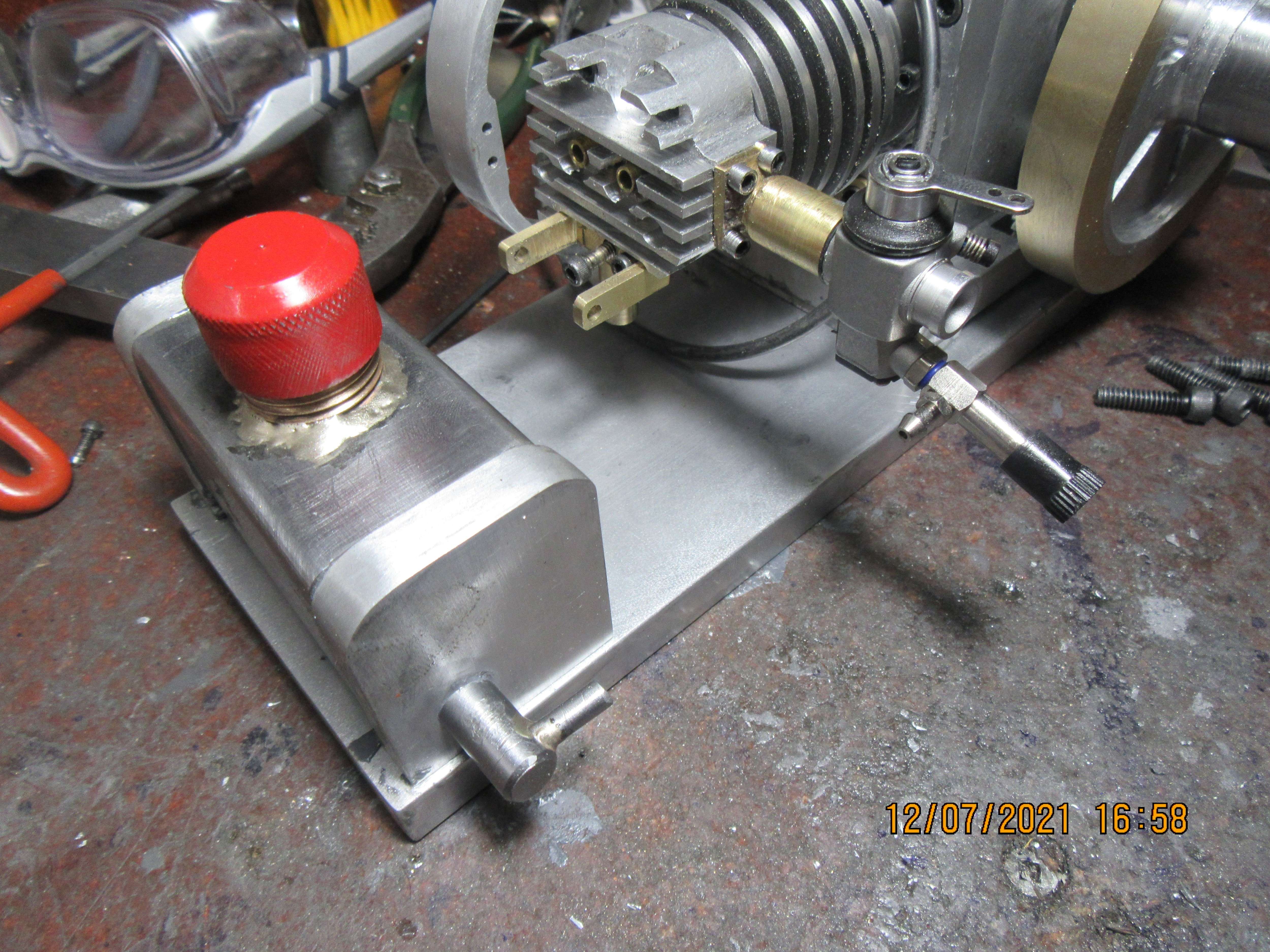
The engine is basically finished. I'm just waiting for a new sparkplug from Steve Hucks. In the meantime, this things needs a gas tank. I've built about a zillion round gas tanks, but this time I decided to try something a bit different. I went out into my "junk steel closet" and found a piece of 1 1/2" square tube. It will be the basis for my new rectangular tank, and I have a piece of 3 1/2" x 1/2" aluminum flat bar that will make a good sub base to hold the engine and the gas tank.
zZd1OP.jpg
 
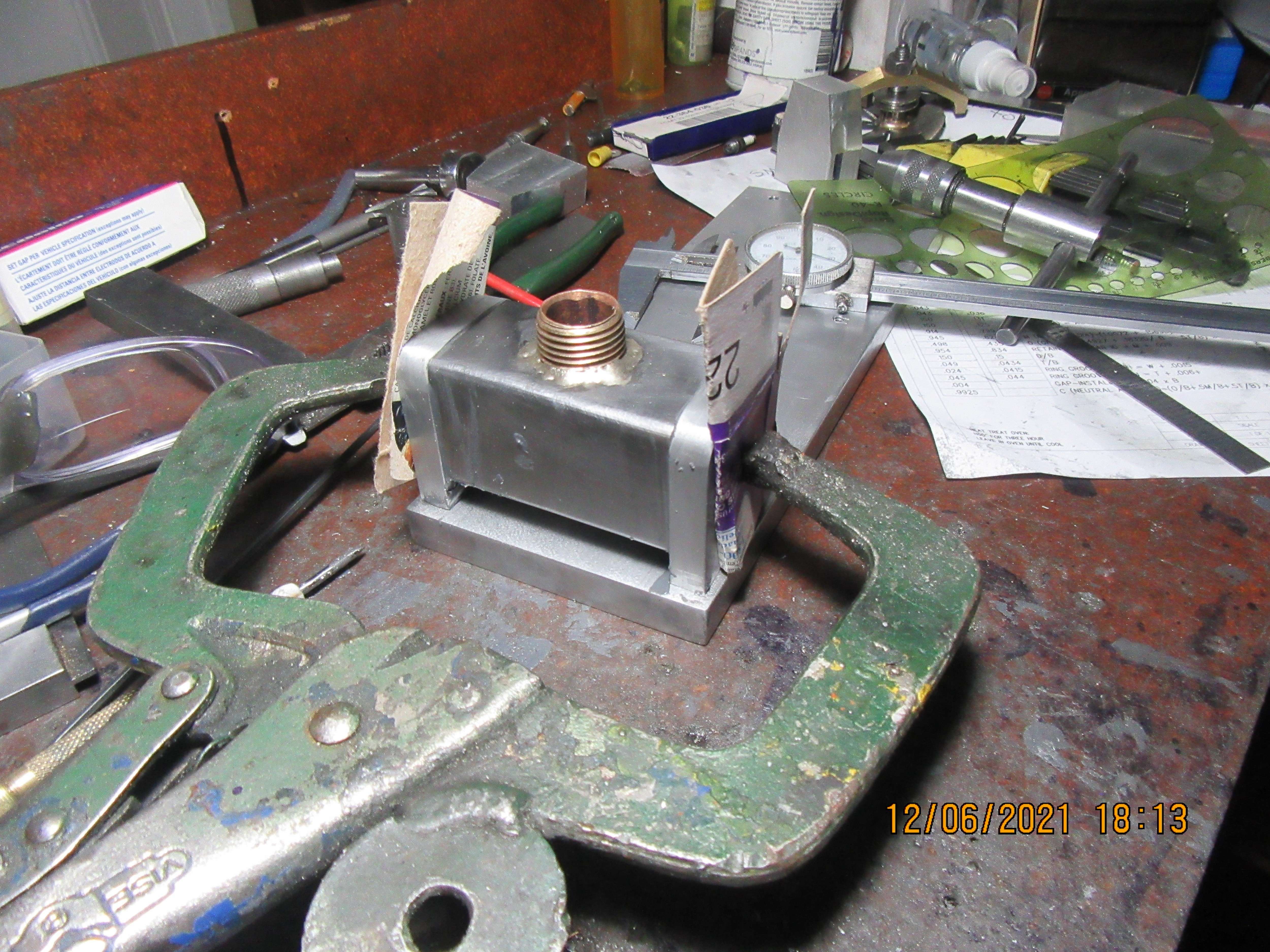
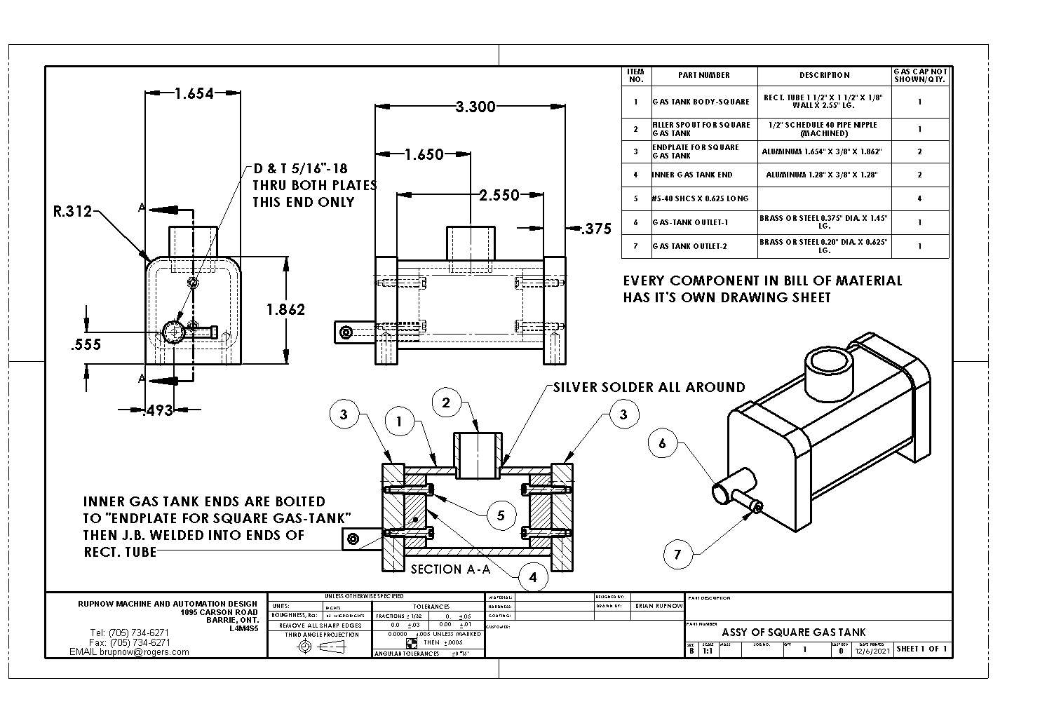
Today the gas tank was assembled. There is a lot going on here that you can't see, but the ends of the tank are assembled to the body using J.B. Weld. The tank assembly is bolted down to the sub base, and the big vice grip clamp is on there as secondary means of clamping things tight for the next 24 hours. The sub base has had all of the holes added to hold the engine and the gas tank. Tomorrow I will leak test the gas tank, and if all is well I will paint the gas tank and the fan assembly.
R1CzS9.jpg

IcmbJ6.jpg
 
Every day I do a little bit more (gas tank out spout), but I'm almost out of little things to do. That red gas cap is "borrowed" from another engine, so I still have to make one of them for this tank. The filler spout is made from a 1/2" standard pipe nipple and the cap is machined from a 1/2" standard pipe plug. This is the best solution I have found for a nice big filler spout that has a cap that screws on tight---and yes, there is a one mm hole in that cap.
MFqqed.jpg
 
This morning was "Leaktest morning". I sat the gas tank on a sheet of white printer paper, plugged the outspout, and very carefully filled the tank with naptha gas. Almost immediately my white paper started showing evidence of a leak.---CRAP!!!---Closer investigation showed that it wasn't any of the j.b. welded joints that were leaking. It was leaking where outspout #1 was brazed to outspout #2. Dumped the gas back into the bottle, ran out to my main garage and re-brazed that joint. Second leaktest went fine---No leaks. Then I went to grab a can of dark blue enamel to paint the tank and fan assembly, and sure enough--I have every color under the rainbow, but not dark blue. Wife has gone out to a spa with daughter, and I am baby setting our Grand-dog. I'm not sure what kind of dog it is, but it just looks like a larger version of the old pit bull we had for many years. She's very quiet and well mannered so I talk to her while I'm working and take her out to pee every hour.
f55wuw.jpg
 
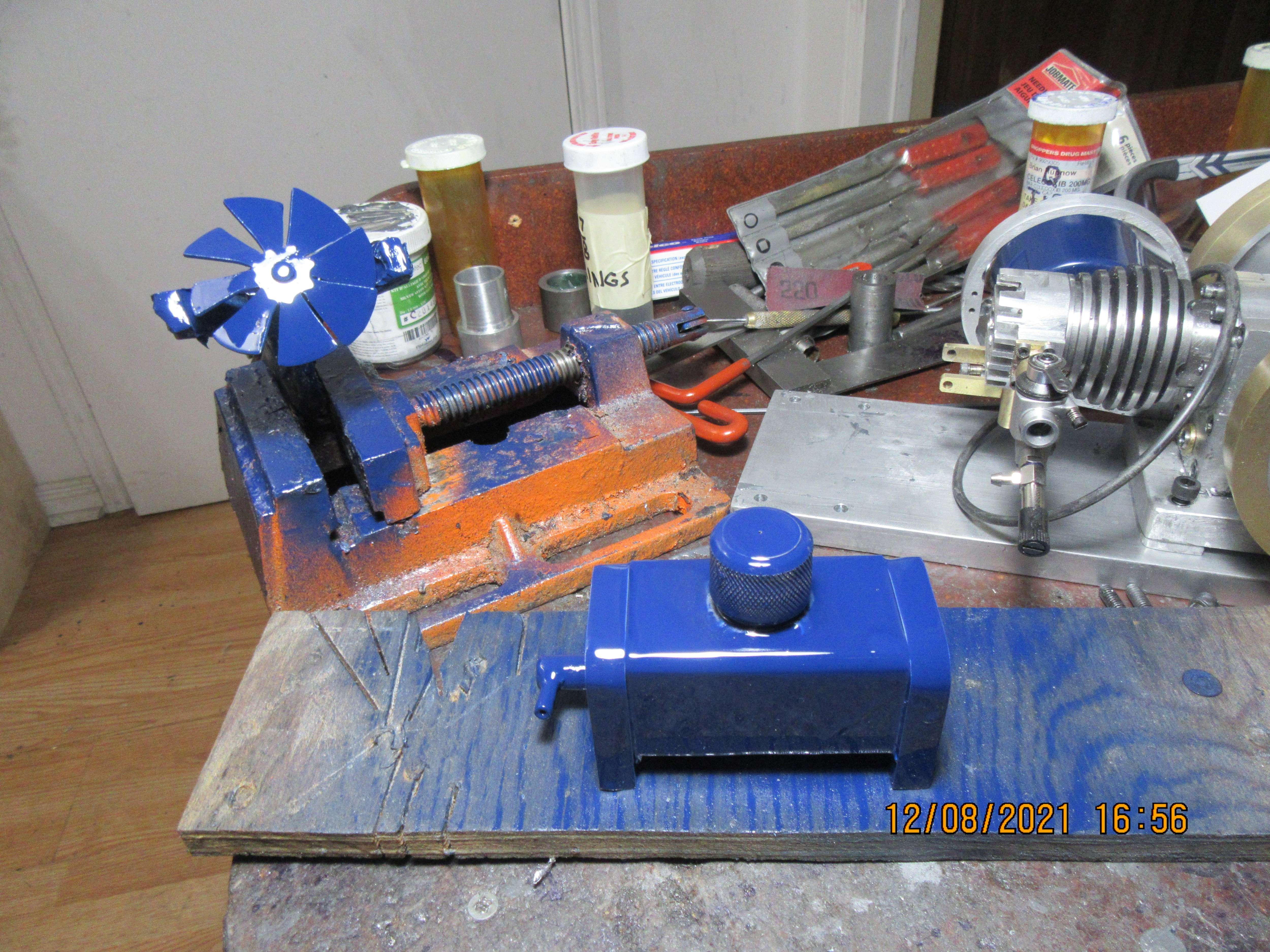
At noon I went out and bought a can of Tremclad blue spray enamel and some brass pipe caps to turn into gas tank caps. I machined both gas caps and screwed one onto an engine which I had robbed the cap off and screwed the other onto the tank for this engine. Both tank and fan assembly have been painted, and I see as I posed them for this camera shot that the cap on this current tank needs a bit more paint on it. That was my work for today. My new sparkplug from Steve Hucks should be here this week, and if I have lived a clean and useful life I may have a running engine by this time next week.
hhT6IY.jpg
 
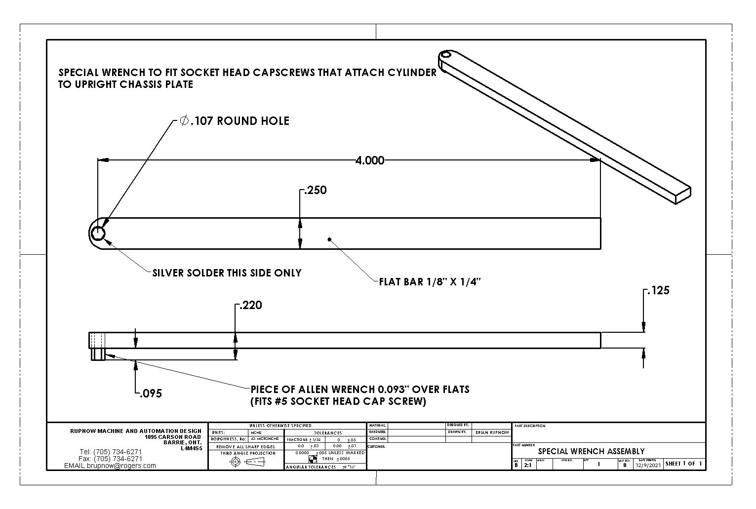
Time to stop and consider---What is left to do? My new sparkplug will be here this week. Head has to be bolted in place and a head gasket made. Valve lash has to be adjusted and valve timing set up with a degree wheel. Ignition timing has to be set. Painted gas tank and fan have to be bolted back into position. I find that with these spray cans of enamel, it is much safer to not handle the painted parts for about three days so as not to get marks all over them during handling them. I have to make a special wrench. It is very, very tight where the base of the cylinder bolts to the vertical frame plate. I can get the bolts started with a ball end Allen wrench, but I'm going to have to fabricate a special wrench to actually get in there and tighten them properly. I will post a picture of the wrench I'm going to have to build-----it's quite simple.
U0UkZ9.jpg
 
Last edited:
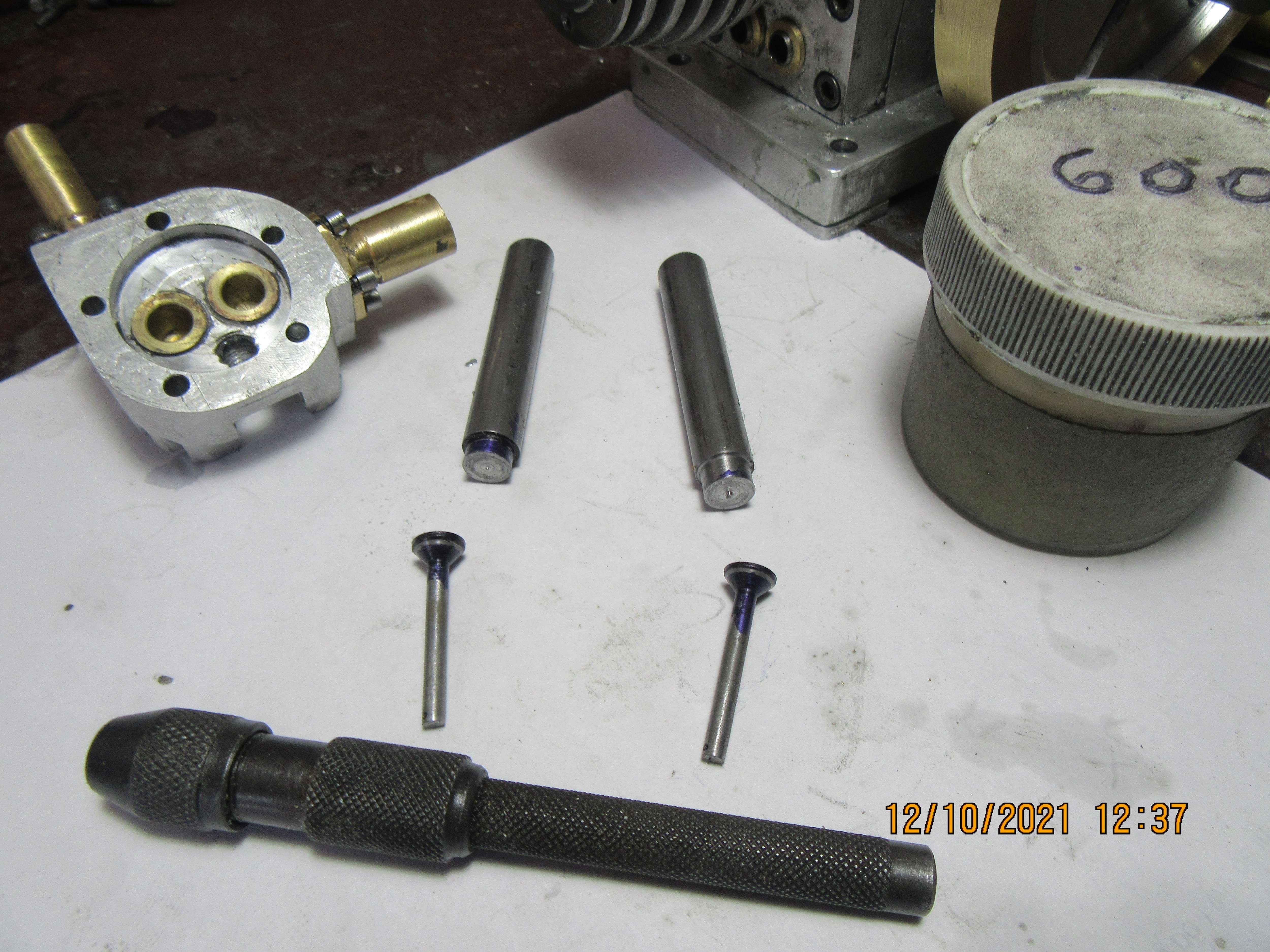
In this picture you can see both valves after they have been lapped using 600 grit aluminum oxide paste. The valves have the contacting surface of the face smeared with 600 grit paste and then (while the handles are still attached) they are placed into the respective valve cages and spun back and forth against the valve seats under slight pressure. This is not done with any kind of power tool---fingers only. I hold the handle between thumb and finger and spin them back and forth 10 times--Then lift up. Turn about 30 to 40 degrees then repeat. After a total of 100 "back and forths" they are finished. Then the "handles" are parted off in the lathe. Beyond this point, the valves must go back into the valve cage in which they were lapped. Don't mix them up. Normally, at this point they are finished, but to make it clear for the picture, I put some blue machinists die on the valves, and using the pin vice in the foreground I gave each valve 50 additional turns in their cages with 600 grit. This clearly shows the contact area on the face of the valves, because all the machinists die is worn away at this point.
vOX3AO.jpg
 
When QC'ing a valve's contact area with bluing, it's important to not spin the valve. You should drop the valve into the seat, and rotate it just a few degrees plus and minus. If your seat has a single tiny leak-creating high spot, and if you spin the valve 360 degrees over this high spot, a contact ring will show up on the valve due to this high spot rubbing on it, and you'll get a false indication of full contact. - Terry
 
I can buy that Mayhugh. These valves are only 5/16" diameter and have been lapped before they were blued. The only reason for bluing them was to show people where the valve contacted the seat in order to seal.
 
For marine engines when we lap valves in their seat, we draw lines on valve seating area with a pencil.
The valve is then rotated on the seat. If all the pencil lines disappear after one rotation the valves are seating perfectly.
This was for old engines.
In new engines the valve and seat are at different angles, so no lapping only grinding in a valve grinding machine.

Regards
Nikhil
 
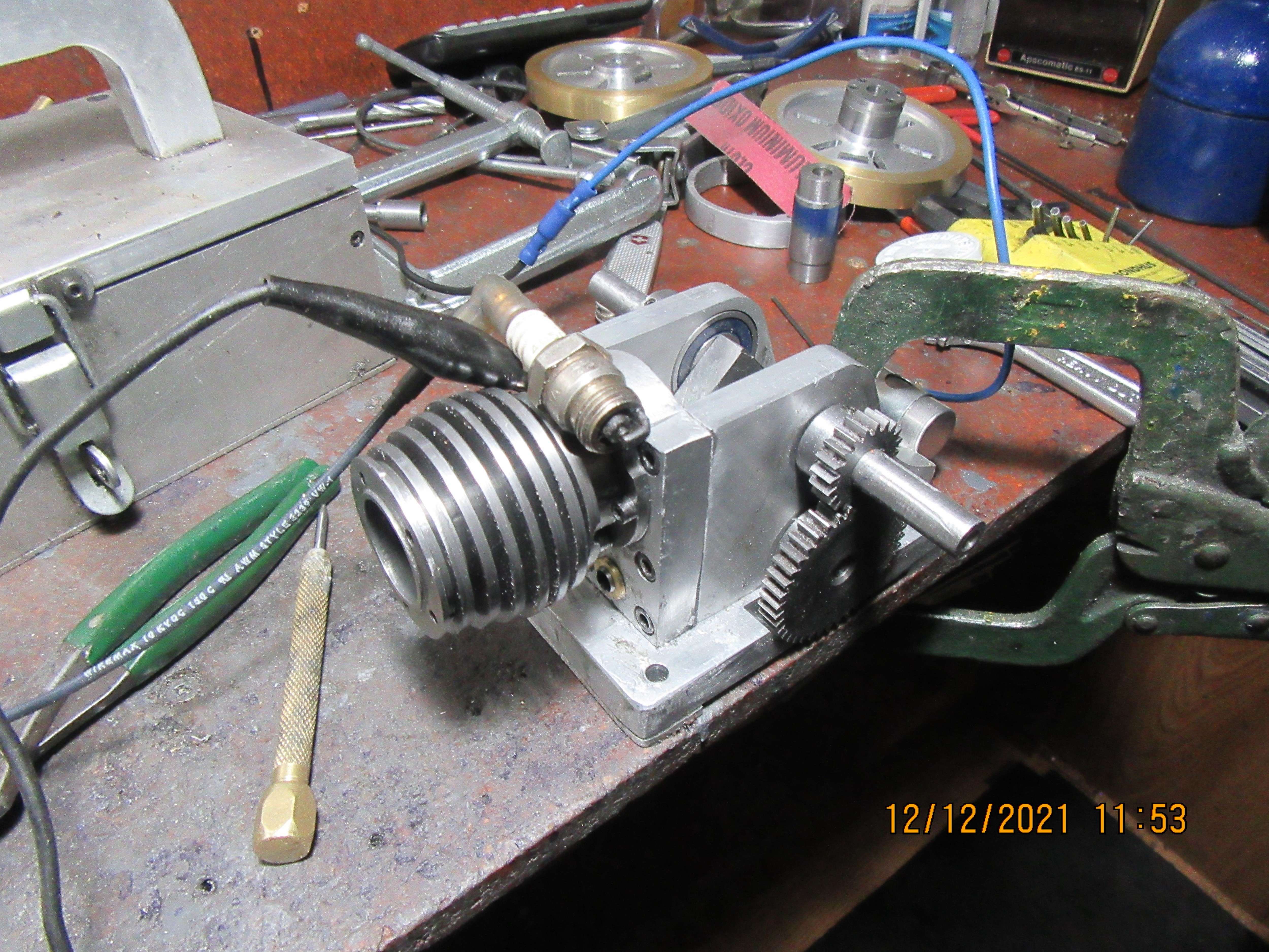
I have reached a point where I can not go any farther with this engine until I receive my new sparkplug. This morning I pulled both flywheels off and set the engine's ignition timing. (I realized after the fact that I didn't have to remove the flywheel from the side with the timing gears on it). Basically, the way I do this is loosen off the set screws in the ignition cam then turn the crankshaft in it's normal rotation until the piston is about 1/16" before top dead center. At this point, without moving the crankshaft, I rotate the cam in it's normal direction until I get a big fat spark from the sparkplug laying out on top of the engine. Then I tighten the setscrews in the cam to lock it in place. After that I turn the engine over by hand a few times just to assure that the spark will come every time the piston reaches that spot 1/16" before top dead center. On my engines I run the ignition points off the crankshaft, so it is a "waste spark system". I get spark every time the piston comes up to top dead center, but it only ignites a charge of fuel every other revolution of the crankshaft.
mKB1lb.jpg
 
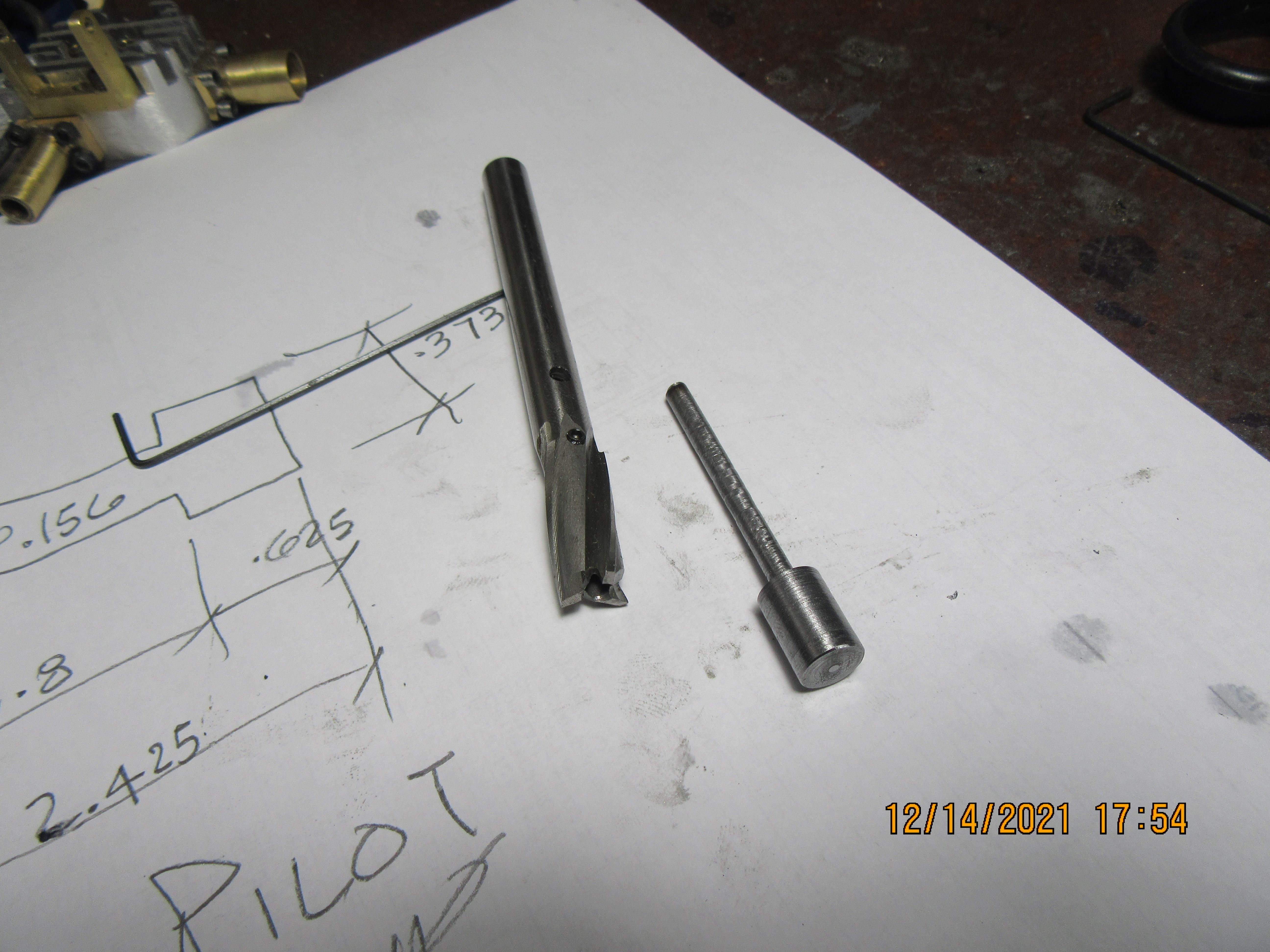
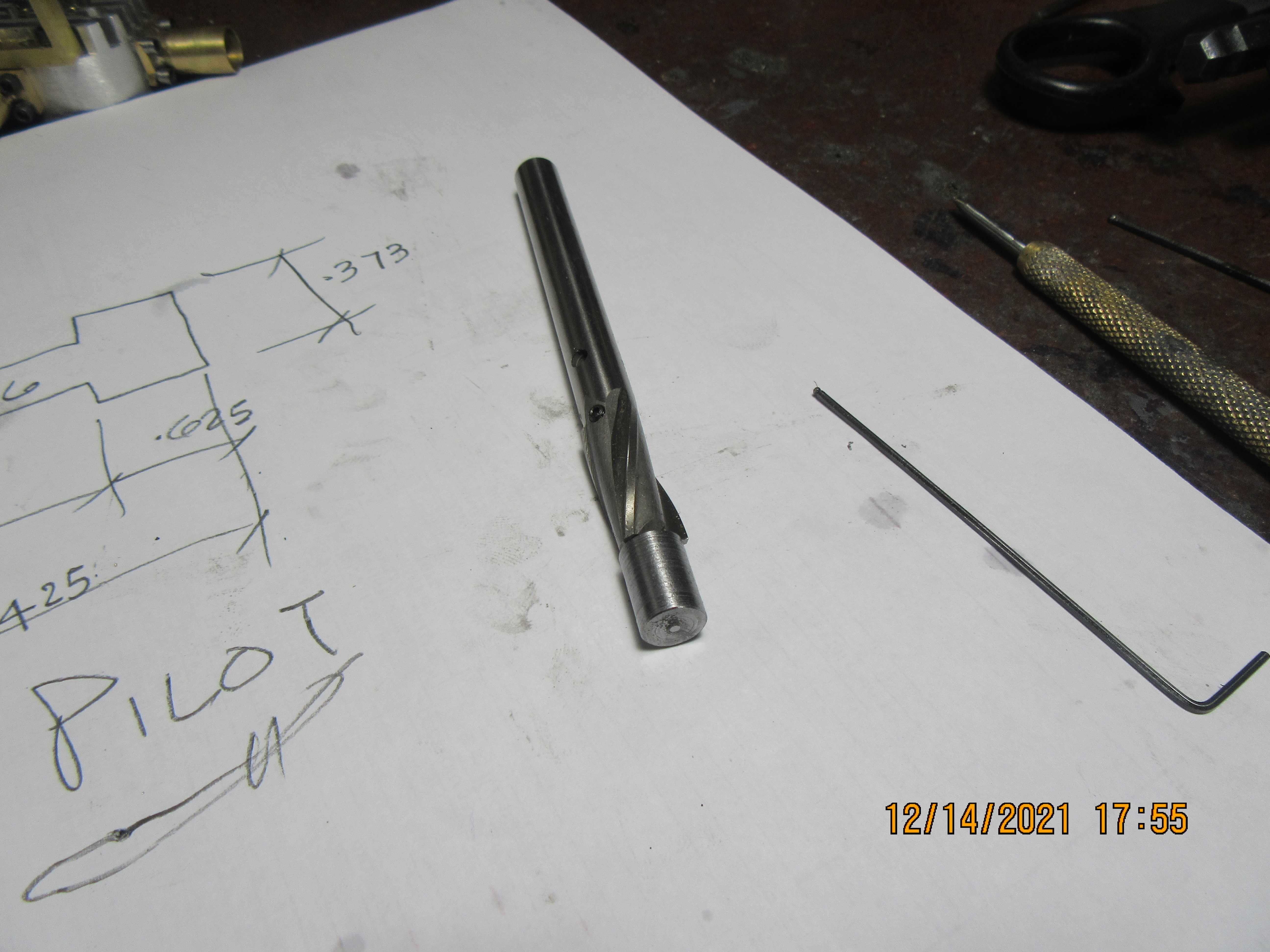
Today I received a new mail order piloted counterbore from Travers. I have a set of counterbores for all of the different socket head cap screws that I have, but this one is a bit different. This one was purchased for the sole use of putting counterbores into aluminum cylinder heads where the flanged end of a valve cage goes, so that the face of the cage sets down flush with the inside of the cylinder head. I have found, by experience, that when I drill and ream these holes, then change to an unpiloted counterbore in the same set-up , that the unpiloted counterbore always pulls a bit to one side and is never totally concentric with the 0.375" reamed hole which the cage body sets into. For this first shot, I have made my own pilot, which sets inside the 7/16" counterbore tool and is held in place with a pair of set screws. I wanted to have the capability of using different size pilots, that's why I didn't buy a one piece counterbore with a pilot ground onto the end of it. It's not too often that I buy a new piece of tooling, so figured it was worth posting about. I'm still waiting for my new sparkplug to arrive, so I can go ahead and finish up the horizontal i.c. that I have been working on.
y6fY8C.jpg

9WBD1E.jpg
 
That counterbore looks like it will do the trick. I applaud your skills again. I myself would not have thought of making a pilot, but would have been a slave to the tool vendors again. The pilot looks like something easily made to solve a user's problem.

...Always watching and waiting for the engine to run,

--ShopShoe
 
Brian:
What difference does it make if the counterbore/mill cutter cuts a little bit oversize? It will not leak around that part of the valve seat. The seal is in the stem of the valve seat, not that short shoulder. Actually why do you need a shoulder at all? The seat is either a press fit or locktite in place and once it is in place it will not move.
 
Gordon---the flange on the valve guide is there because---I have this terrible fear that without a flange, the Loctiite would heat up from the engine running, and as I hover over the engine running it, the engine will fire and shoot valve guide with valve attached out and hit me in the eye. Shopshoe---These piloted counterbores and different size pilots are readily available from toolshop suppliers.---Brian
 
Back
Top