I have not reached a decision yet. I am waiting for the sparkplug I ordered to show up. If the sparkplug isn't 8 mm thread, I perhaps can turn the threads off, leaving a 5/16" or 8 mm plain end that I can then thread to 5/16". I have also thought about j.b. weld, and a dozen other things, but I'll get the sparkplug I ordered first.
You are using an out of date browser. It may not display this or other websites correctly.
You should upgrade or use an alternative browser.
You should upgrade or use an alternative browser.
Horizontal Air Cooled Engine
- Thread starter Brian Rupnow
- Start date

Help Support Home Model Engine Machinist Forum:
This site may earn a commission from merchant affiliate
links, including eBay, Amazon, and others.
Something to add to the insert plug option mentioned might be to make it an interference fit. Similar to how valve guides go in with some heat and dry ice.
IMHO I don't think JBweld or other epoxies can be anything other than a bodge job. Not of the standard of your workmanship. If there is insignificant room to over-bore thread and fit an insert, then the simple repair for aluminium is a blow-lamp ally weld rod. I used to you the heavily zinc based rods, but there are now some very cheap (€&@y) alloy rods that are 90+% aluminium, but melt flow and take to your aluminium below the melting point of your aluminium.
I have used it as a solder on 1mm thick aluminium, 3mm thick, and other small jobs. I have used the zinc-aluminium mixtures to fill holes in thicker ally.
But try an insert first if possible. Least risk to your existing job.
K2
I have used it as a solder on 1mm thick aluminium, 3mm thick, and other small jobs. I have used the zinc-aluminium mixtures to fill holes in thicker ally.
But try an insert first if possible. Least risk to your existing job.
K2
- Joined
- Dec 31, 2010
- Messages
- 819
- Reaction score
- 220
If you thread the insert, the JB weld is just a permanent thread sealant. You don't even see it when it's done. Except for a very fine ring the diameter of the insert. Same for loctite.
I have spent the last two days designing some light automation for an old customer. My new sparkplug will be here on Saturday, and if it doesn't have an 8mm thread I am going to buy a 1/4"-32 helicoil kit from a source provided by Brian Lawrence from Calgary. Tomorrow I will begin the task of making rings for a 7/8" diameter piston. I have the grey cast iron material, but will have to build a new heat treat fixture to accommodate the new ring size. The rings will have the same cross section as the ones I made earlier this year for my T-head engine.

$519.19
$699.00
FoxAlien Masuter Pro CNC Router Machine, Upgraded 3-Axis Engraving All-Metal Milling Machine for Wood Acrylic MDF Nylon Carving Cutting
FoxAlien Official

$89.99
Outdoor Wood Boiler Water Treatment Rust Inhibitor- AmTech 300 & Test Kit
Alternative Heating & Supplies

$94.99
$109.99
AHS Woodmaster 4400 Maintenance Kit for Outdoor Wood Boiler Treatment
Alternative Heating & Supplies

$24.99
$34.99
Bowl Sander Tool Kit w/Dual Bearing Head & Hardwood Handle | 42PC Wood Sander Set | 2" Hook & Loop Sanding Disc Sandpaper Assortment | 1/4" Mandrel Bowl Sander for Woodturning | Wood Lathe Tools
Peachtree Woodworking Supply Inc

$39.99
$49.99
Sunnytech Low Temperature Stirling Engine Motor Steam Heat Education Model Toy Kit For mechanical skills (LT001)
stirlingtechonline

$45.99
Sunnytech Mini Hot Air Stirling Engine Motor Model Educational Toy Kits Electricity HA001
stirlingtechonline

$99.99
AHS Outdoor Wood Boiler Yearly Maintenance Kit with Water Treatment - ProTech 300 & Test Kit
Alternative Heating & Supplies

$180.50
$190.00
Genmitsu CNC 3018-PRO Router Kit GRBL Control 3 Axis Plastic Acrylic PCB PVC Wood Carving Milling Engraving Machine, XYZ Working Area 300x180x45mm
SainSmart Official
![DreamPlan Home Design and Landscaping Software Free for Windows [PC Download]](https://m.media-amazon.com/images/I/51kvZH2dVLL._SL500_.jpg)
$0.00
DreamPlan Home Design and Landscaping Software Free for Windows [PC Download]
Amazon.com Services LLC

$39.14
$49.99
Becker CAD 12 3D - professional CAD software for 2D + 3D design and modelling - for 3 PCs - 100% compatible with AutoCAD
momox Shop
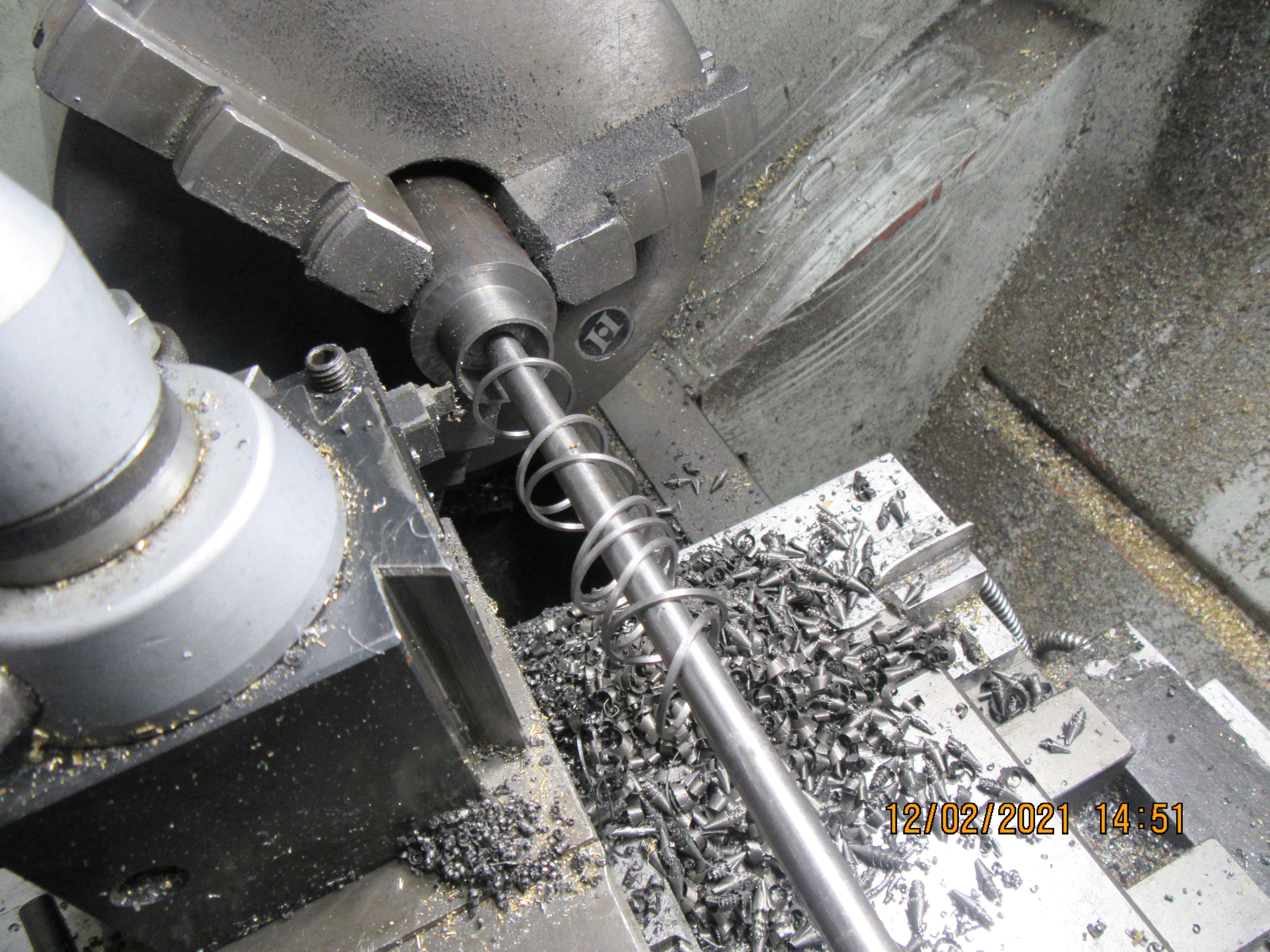
Todays job was to make a whole armada of 7/8" rings. The material is fine grained grey cast iron, same as I made my other 1" rings from. The o.d. of the ring is turned to 0.875" diameter and polished with 200 grit aluminum oxide strip and a fine India stone, to the best finish I can get. The i.d. is drilled and bored out to leave the rings 0.038" wide axially, which is what I was aiming for. The rings are then parted off, and with some luck will all be slightly greater than 0.045" width, which is the width of the ring grooves in my piston. They will be finished on both sides with some 600 grit aluminum oxide paste on a sheet of glass, rubbing round and round until they are a sliding fit into the ring grooves in the piston. After they are "sized" for width, I will break them in my bench vise. I don't like the fancy fixture which I made to split them because it has a tendency to bend the rings. The last rings I made were cut with a sharp cold chisel, but I felt that doing that deformed the ring on both sides of the cut.

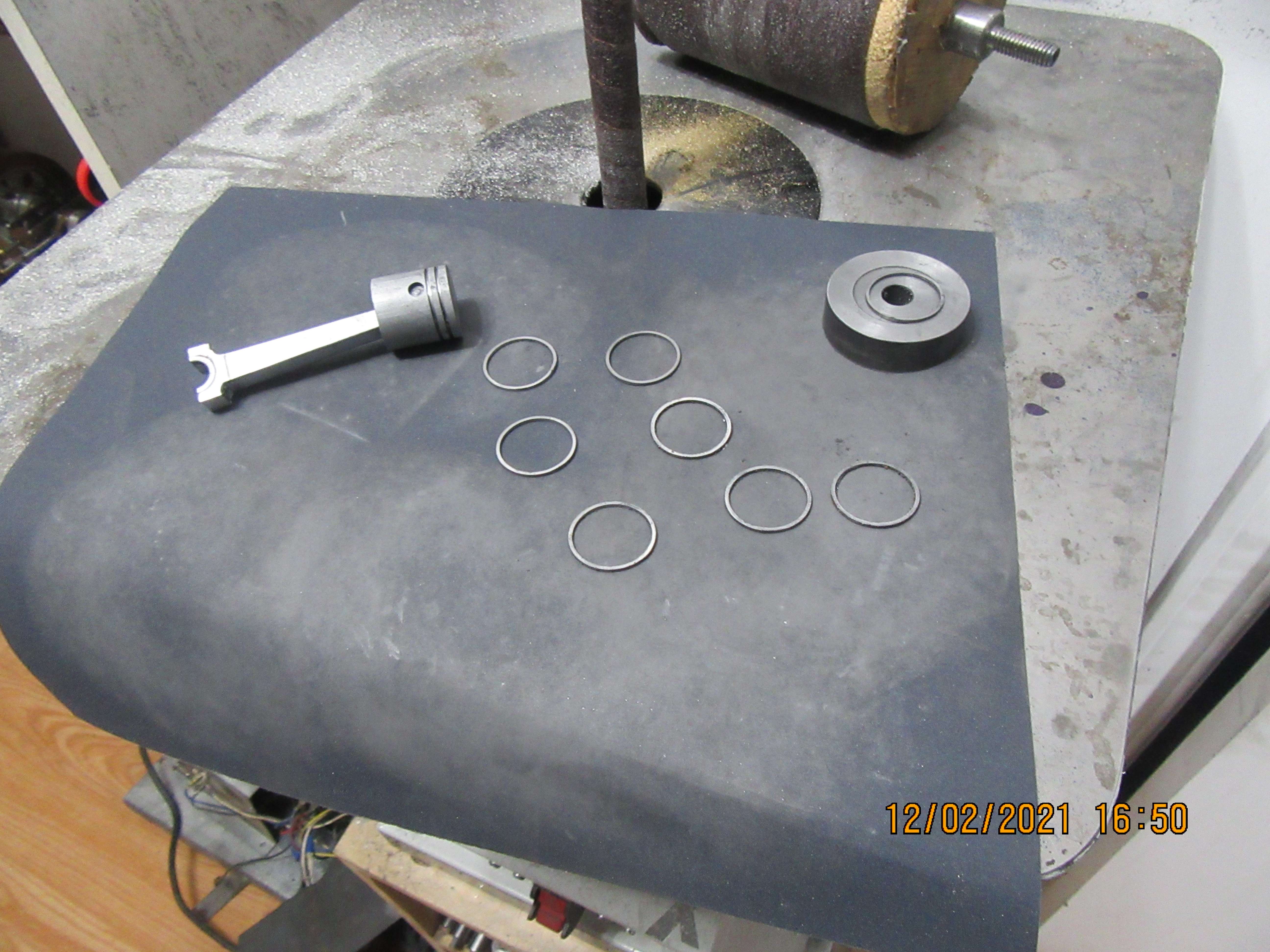
Okay---Just to set the record straight---My rings came off the lathe about 0.003" to 0.004" too wide (as I had planned). I tried polishing that 0.003" to 0.004" off using 600 grit compound on a piece of glass, but it took so long I thought I might not live long enough to get all the rings done.---So---I used a sheet of 600 grit paper laying on a finished cast iron surface, and my handy dandy piece of steel with a 0.875" dia. x 0.025" deep hole in it to hang onto the rings with while I polished them. That went more quickly, but even so it took a lot of scrubbing in circles before the rings came down to 0.044" thick and would fit into the 0.045" grooves in my piston.

MRA--I misled you.
This was something new---The material didn't want to break in the vice. Damn stuff wanted to bend, which is unusual. When I seen that it didn't just snap quickly like other rings have made, I sharpened up my big cold chisel and cut them with the chisel and a pall peen hammer. Whack---and it was done. All the rings in this picture are finished, deburred, and split. Tomorrow I will machine a heat treat fixture and into the heat treat oven they go.---Brian
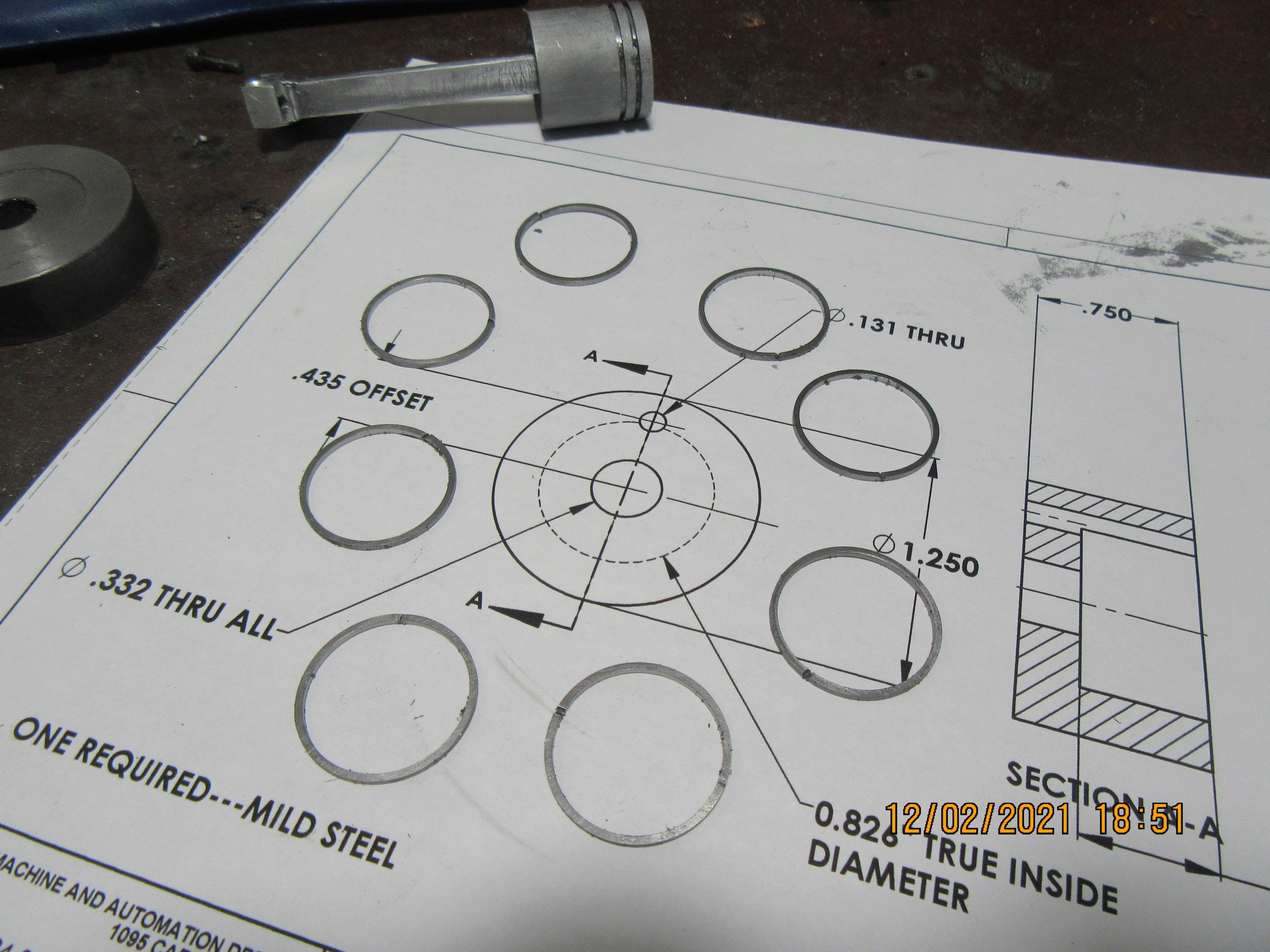
This was something new---The material didn't want to break in the vice. Damn stuff wanted to bend, which is unusual. When I seen that it didn't just snap quickly like other rings have made, I sharpened up my big cold chisel and cut them with the chisel and a pall peen hammer. Whack---and it was done. All the rings in this picture are finished, deburred, and split. Tomorrow I will machine a heat treat fixture and into the heat treat oven they go.---Brian

Last edited:
Is it possible that you got ductile iron rather than grey cast iron? It would be more inclined to bend than snap.MRA--I misled you.
This was something new---The material didn't want to break in the vice. Damn stuff wanted to bend, which is unusual. When I seen that it didn't just snap quickly like other rings have made, I sharpened up my big cold chisel and cut them with the chisel and a pall peen hammer. Whack---and it was done. All the rings in this picture are finished, deburred, and split. Tomorrow I will machine a heat treat fixture and into the heat treat oven they go.---Brian

I was thinking the same when I saw that swarf from drilling out the waste, looks more like ductile iron.
If it is the same bar you used for the others that may also explain why the Trimble cutter was deforming the ring around the split.
If it is the same bar you used for the others that may also explain why the Trimble cutter was deforming the ring around the split.
Could very well be. I've broken rings in my vice in the past, and they always cracked under light sideways pressure. I have never n one bend before.
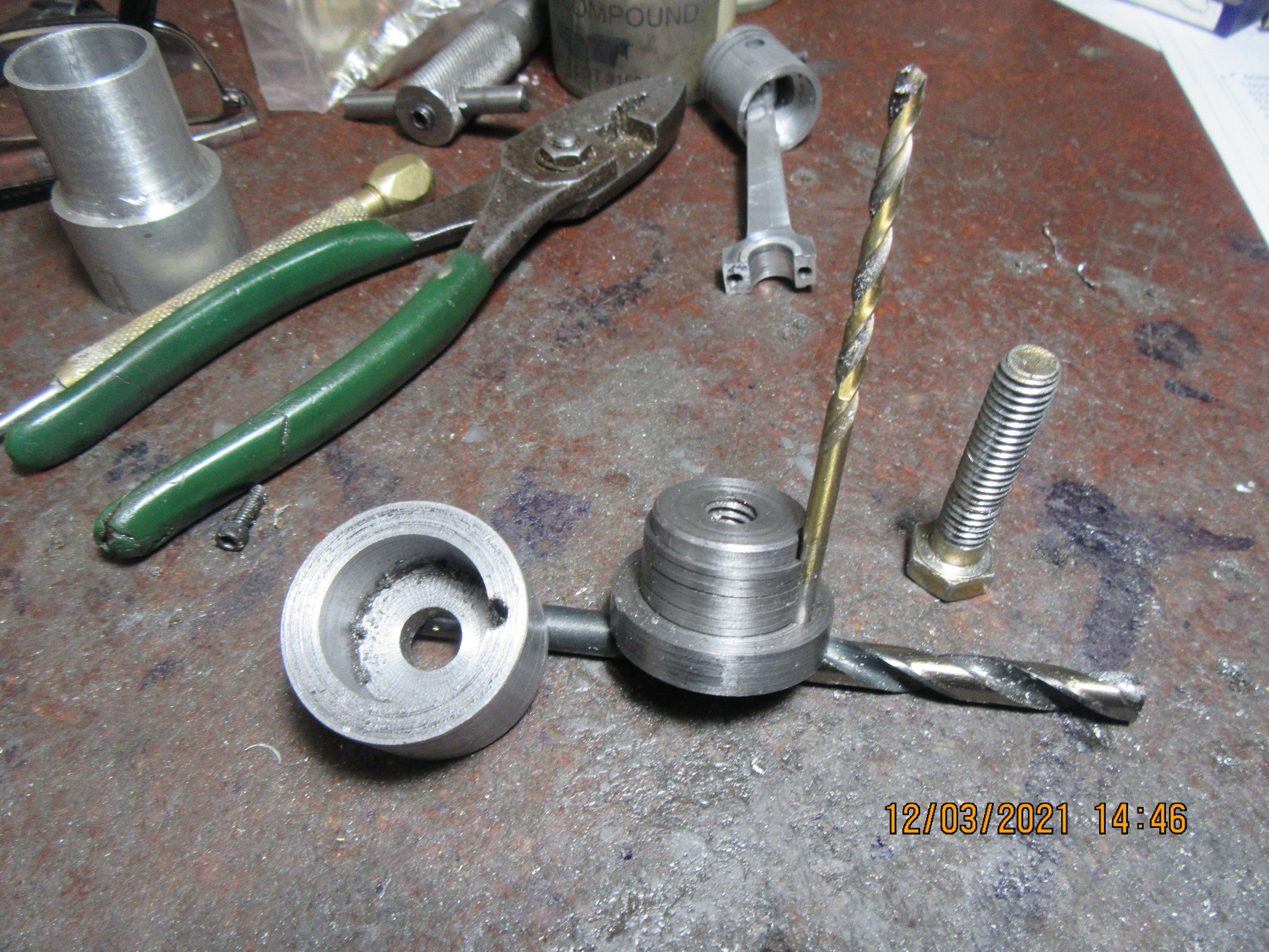
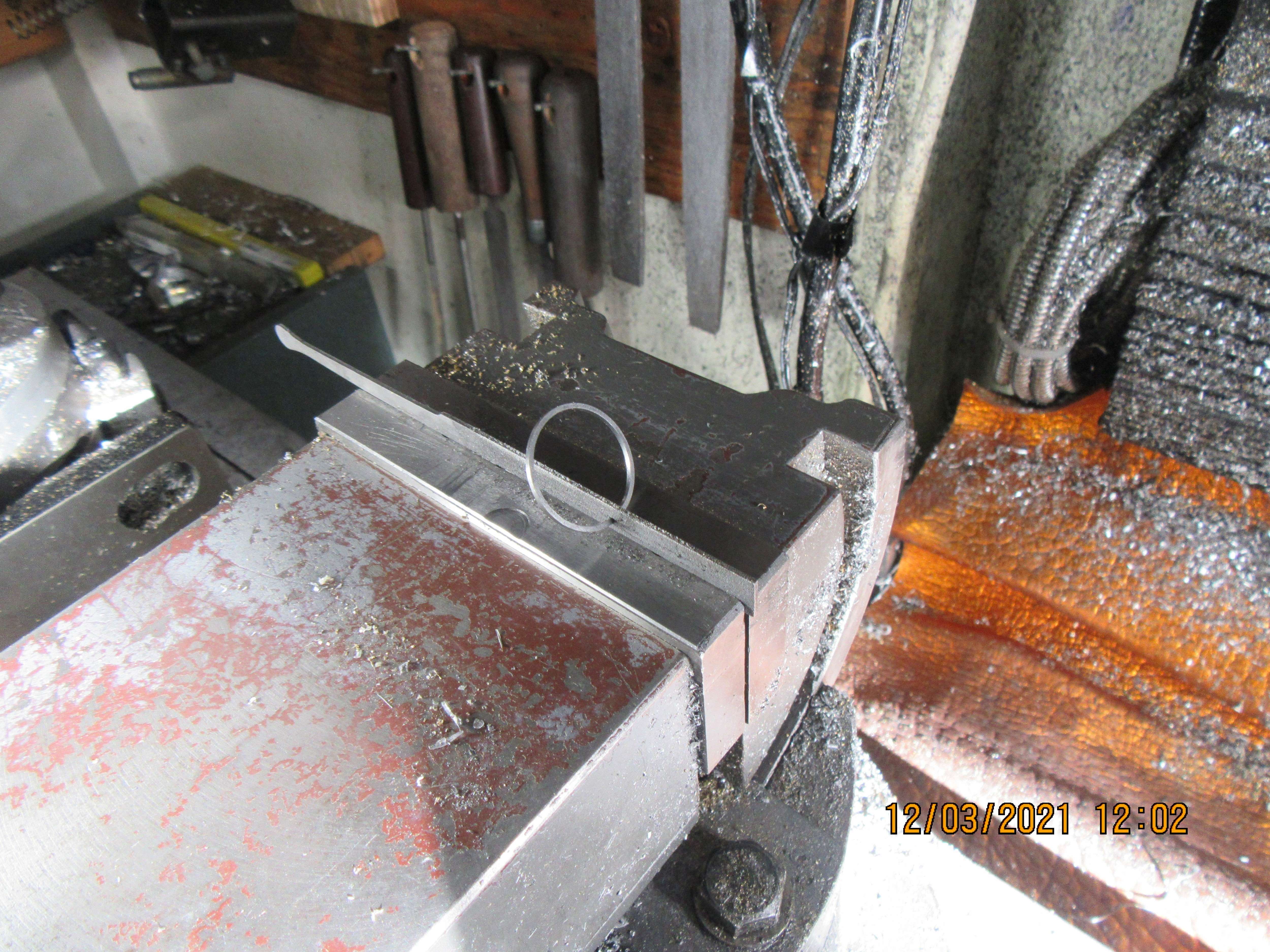
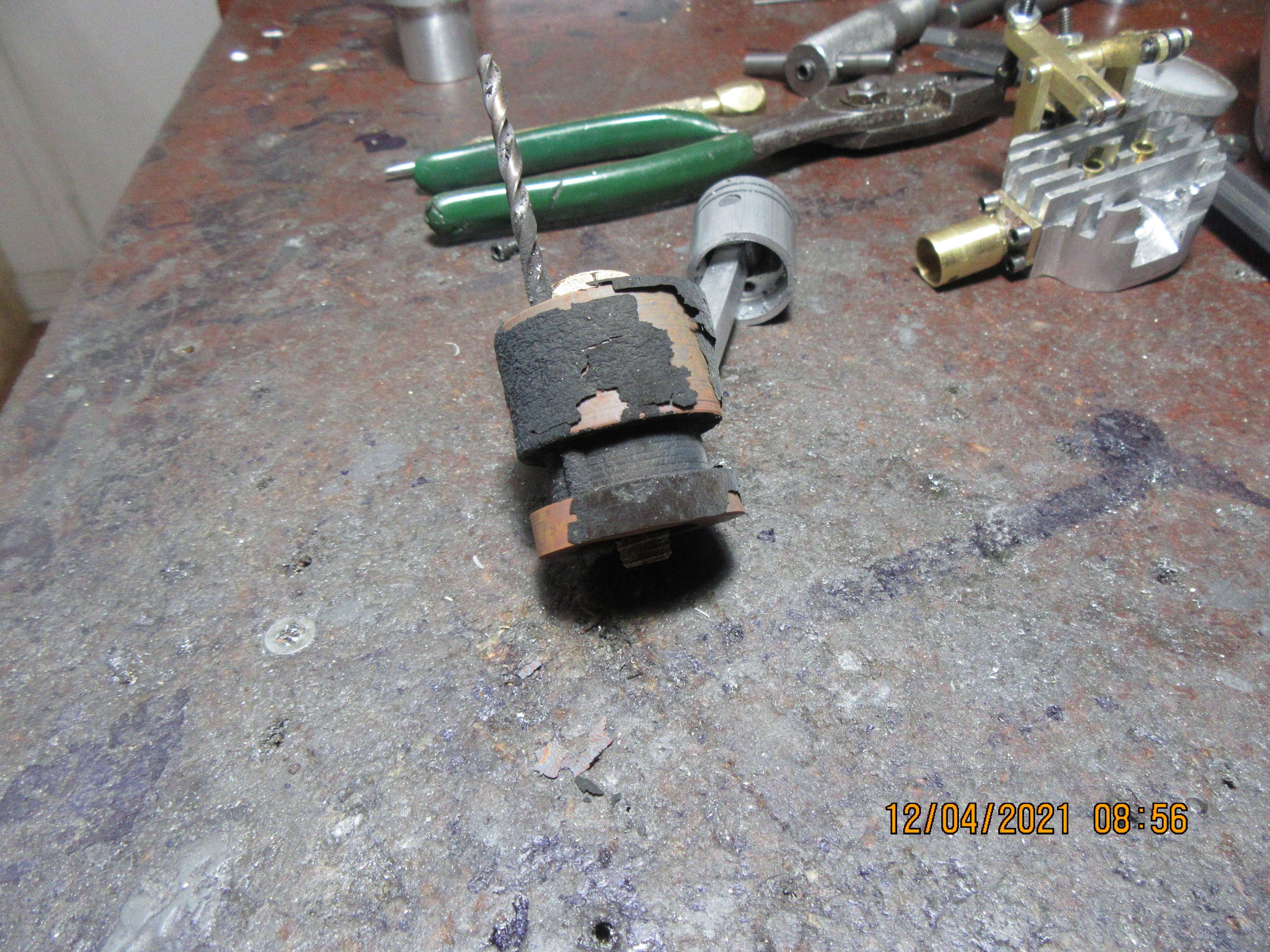
A couple of picture worthy things going on here. One picture shows a good way of filing the ends of the ring at the ring gap. That is an ignition points file gripped in the vice, and a ring spread over it. I grip the ring with thumb and forefinger of each hand and slide it back and forth on the file, keeping it "square" to the file. Give it 20 strokes and try it for fit in the cylinder--You are aiming for a gap of 0.004" between the ring ends when the ring is slid into the cylinder. Keep track of the number of strokes you take, because whatever it took for that first ring will work for all the rest of the rings. The other picture shows the heat treat fixture I machined this morning, made specifically for 7/8" rings. The drawing I am working from specifies a 0.131" diameter spreader rod. Closest I had was an 0.135" drill, so thats what I used, and the drill will be sacrificed as my spreader rod. Once the cap is bolted on, compressing all of the rings to ensure that they are all laying flat and tight next to each other, the fixture and rings go into my heat treat furnace for 4 hours.



Last edited:
The drawing I am working from specifies a 0.131" diameter spreader rod. Closest I had was an 0.035" drill, so thats what I used, and the drill will be sacrificed as my spreader rod.
Is that a typo? Those are a tenth of an inch different? I mean is it supposed to be 0.131 and 0.135 or .031 and .035?
That was a typo Bob.--thanks. I fixed it.---Brian
Bad on me---I ordered an M8 sparkplug from A.C. Delco, assuming it would have an M8 thread on it.---it doesn't. It has a 10 mm thread on it. However, all is not lost. As we speak, Stephen Hucks is making me a "one of" sparkplug with a 5/16"-24 threaded end. As luck would have it, I do have a 5/16"-24 tap and die as part of a set I inherited from my dad.
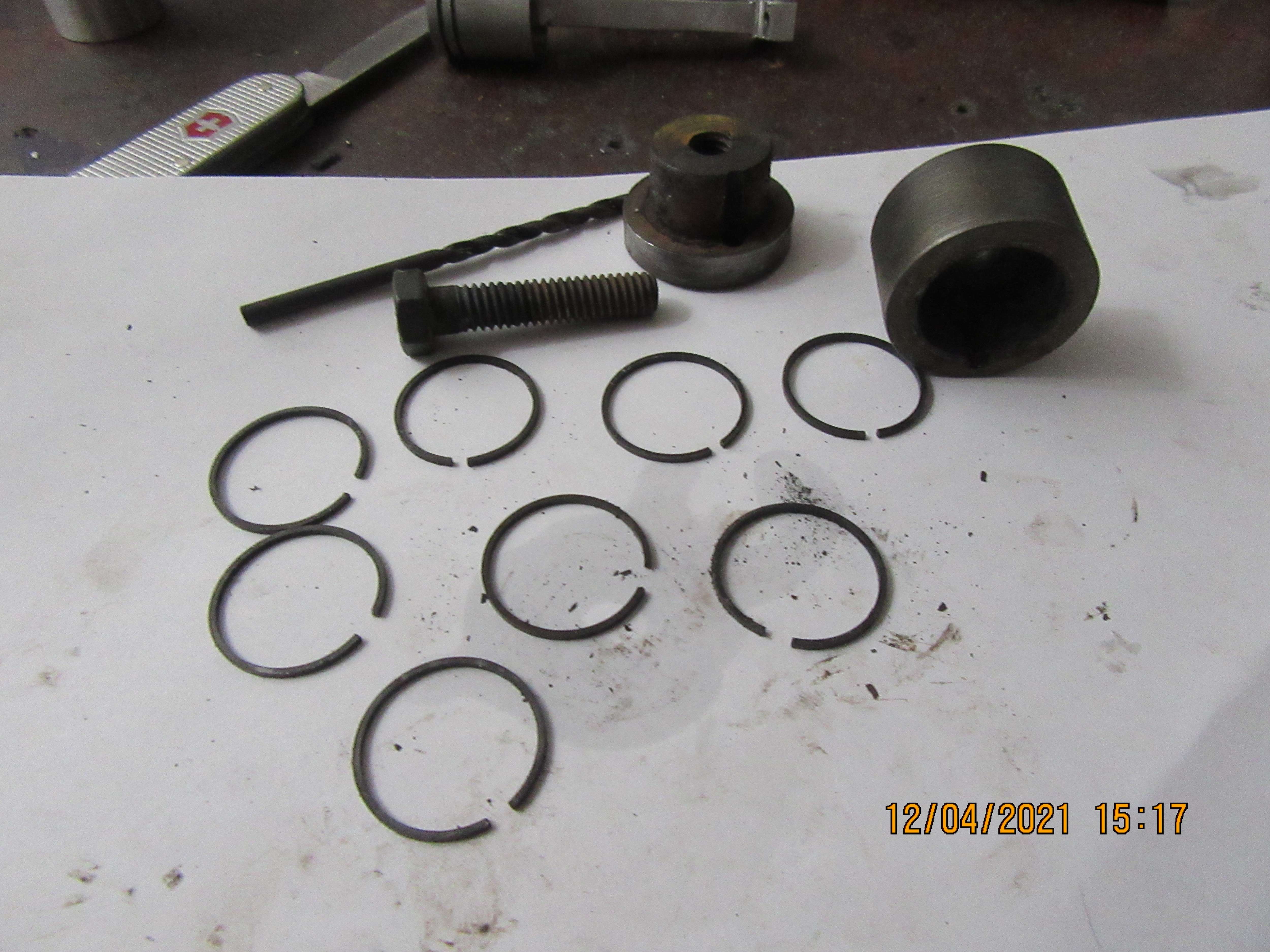
After four hours at 1100 degrees F and then an overnight cooling off period, the fixture comes out of the oven looking like this. There is a lot of black crud on the outside of the fixture (Don't know what it is) but it cleans off very easily. When the fixture is taken apart, the rings come off easily, but they are all stuck together. A bit of finessing with a jacknife gets them apart, and as you can see in the picture they have all taken a set to the new gap of 0.135".


Similar threads
- Replies
- 2
- Views
- 374


