Hit me - Miss me?

Home Model Engine Machinist Forum

Help Support Home Model Engine Machinist Forum:

This site may earn a commission from merchant affiliate links, including eBay, Amazon, and others.
Hi Guys,

Talk about Gerry and the Hat-Tricks. ::) I was wandering aimlessly about our nearest shopping mall yesterday, waiting the interminable wait of one whose better half is a shopaholic when Bam, thought of the week, I'll go and join the local library. :eek:

Found the place, went in and signed my life away thus allowing me to borrow from any of the 5 libraries within our local council.

Lo and behold, leaping off the shelf at me was Tubal Cain's "Spring Design & Manufacture," No. 19 from the Workshop Practice Series.

Aha, I need to make some valve springs and governor springs for this engine, just the thing.

As one who has used many springs over the years I had never given them much thought. Wow, they are a science and an art in their own right.
wow.gif


A great little book and I hope I can do it justice when the time comes.

Best Regards
Bob
 
Talk about Gerry and the Hat-Tricks.
:big: :big: :big:

Good going on your build Bob, and you still have way too much spring in you to belong to that music group!

Regards, Arnold
 
Thanks to you Arnold, :bow: I sprang into action today. ::)
......................or...............
The spring is sprung
The Grass is Griz
I wonder where the birdies is.

The bird is on the wing.

Don't be absurd, don't be absurd, the wing the wing is on the bird.

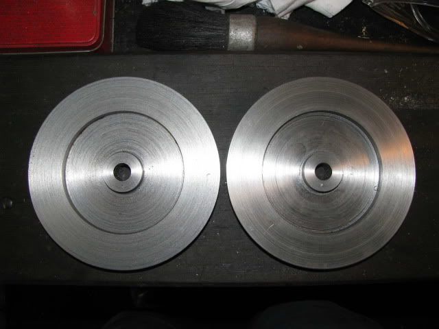
The turning part of the flywheels is finished.
wow.gif


Pictures when the photobucket bird takes wing and springs into action again.

EDIT: Wingdings and Springthings. ................(Photobucket is back online)

IMG_1121.jpg


Best Regards
Bob
 
Congratulations on the flywheels, Bob.
It's been a tough fight, but you won!


Uh, you been nipping at the brandy again??
 
Maryak said:
The spring is sprung
The Grass is Griz
I wonder where the birdies is.

The bird is on the wing.

Don't be absurd, don't be absurd, the wing the wing is on the bird.

:big: :big: :big:

nice flywheels BTW
 
Kevin and Ariz,

Thanks for the support guys. :bow: :bow:

Don't quite know why I was in a whimsical mood yesterday not sure if the cure is more or less brandy. ;D

Best Regards
Bob
 
Well, that's three down, and two done. A 66.6% average, Bob. Not bad!
; )
With all the running around you have to do, I'd say it's getting along fine.

Dean

 
Bob,
Don't worry about the whimsy. Sit back and enjoy it. It doesn't happen often enough in our hectic lives these days.

Of course, more brandy!!! *beer*
 
seagar said:
Is the bird a Galah? Rof}

Ian(seagar)

No just the thread owner. ::)

Thanks guys and I, (but not SWMDBO), like the more brandy idea as well. :bow: :bow: :bow:

Best Regards
Bob
 
;D Good going Bob

I concur with the more rather than less philosophy :) - at the risk of Mrs M condemning this board as a bad influence ;D

Kind regards, Arnold
 
Hi Guys,

1st up thanks Arnold for the continued support. :bow:

Another week in the other sunny SA and I actually managed to scrounge up some Aluminium for the conrod and piston. Yep I even managed to make the piston.

The pieces for the piston and conrod.

IMG_1127.jpg


Regrettably Mr Depenbusch and I disagree about the diameter of the piston v diameter of the cylinder and following from this the size of the piston rings. Attached is a spreadsheet based on the writings of Tubal Cain and Proffesor Chaddock regarding sizes etc. for pistons rings and piston diameters. The ring calculations are based on the cold forming method from "Machining and Fitting 1927" and the writings of Paul Chernokeef.

These calculations and ring forming method have worked well for me in both full size and in a model engine. They are by no means the only way and others have had success hot forming their rings. Each to their own.

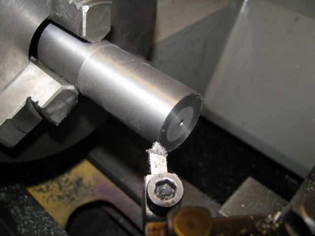
The piston drilled internally.

IMG_1128.jpg


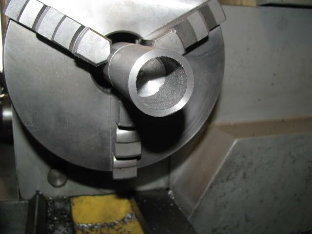
The outside down to size and ready for the ring grooves.

IMG_1130.jpg


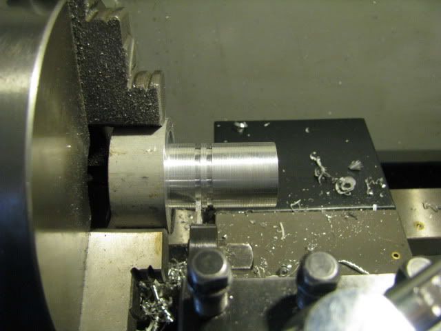
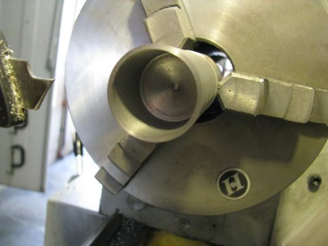
Cutting the ring grooves using a standard parting tool.

IMG_1132.jpg


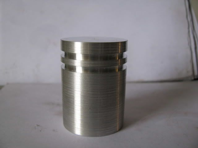
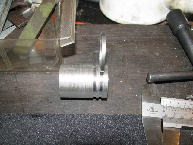
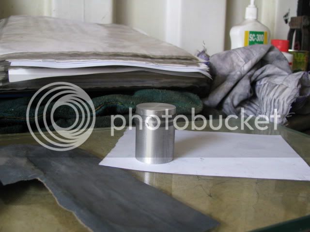
The turning of the piston is complete.

IMG_1133.jpg


Best Regards
Bob


View attachment Pistoncalc.xls
 
Nice Bob,
Looks like you turned the Conn rod/wrist pin clearance area inside. Any reason instead of a milled slot?

Tony
 
Tel,

Thanks mate for your continued support. :bow:

cobra428 said:
Nice Bob,
Looks like you turned the Conn rod/wrist pin clearance area inside. Any reason instead of a milled slot?

Tony

Tony,

No reason - just followed the drawing - if it's NBG make another piston. Perhaps I should rename the thread "Hit Me-Miss Me Twice."
Thanks for your continued interest. :bow:

Today was a god day in the shop and I managed to get the ring blanks made. Nest week will be splitting, gapping and forming.

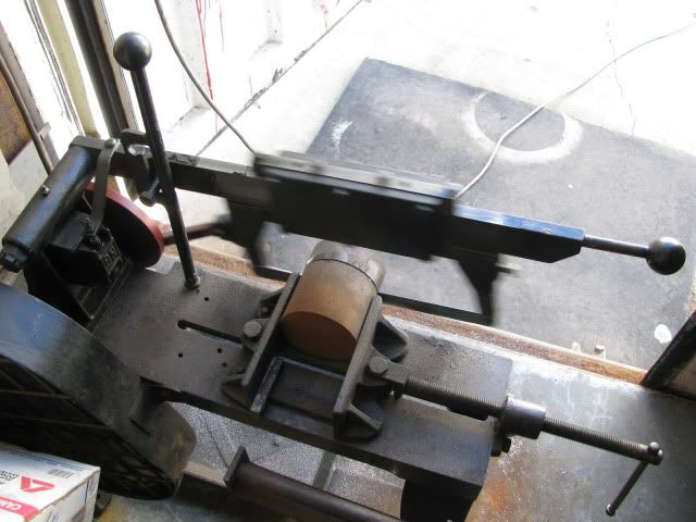
Hacking off a lump of spun cast iron.

IMG_1134.jpg


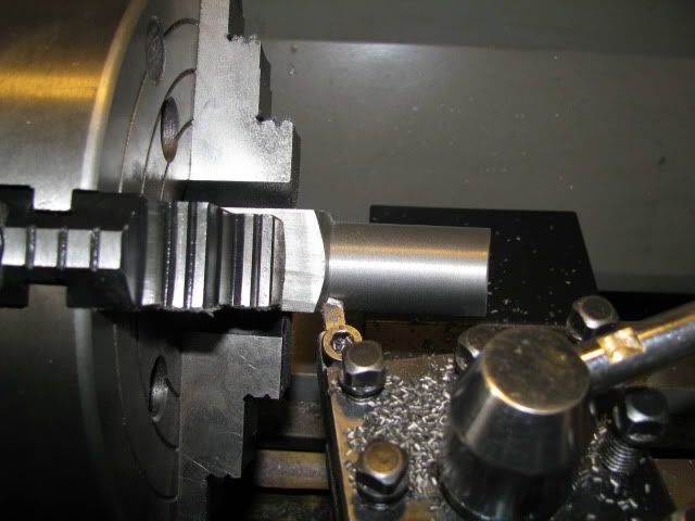
Roughing the ring blank OD.

IMG_1135.jpg


Ready for drilling and boring.

IMG_1136.jpg


Drilled.

IMG_1137.jpg


Bored.

IMG_1138.jpg


Testing the axial width with the piston.

IMG_1139.jpg


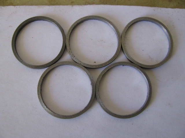
Rings of Olympian proportion, (if your like me - ham fisted - it's always a good idea to make extras for the ones you managed to break).

IMG_1140.jpg


Best Regards
Bob


Haha, nice work Bob :big:

I was going to ask about the clearance for aluminium piston with cast iron cylinder. Thanks for sharing the spreadsheet.

When I tried the aluminium piston on my flame licker it all siezed up!

Nick
 
Nice photo series on the rings, Bob. Here's hoping you have three spares!

Dean
 
Nick, Dean and kvom,

Thanks for your continued support and interest. :bow: :bow: :bow:

Last week saw the cast iron piston ring blanks completed and this week the manufacturing of the piston rings was completed.

I thought I would try and present a more detailed description of how I go about making these rings using a cold forming method. Firstly the ring material must be spun cast iron. I have tried other forms of cast iron and it does not work! The rings have no or at best, insufficient spring and will not adequately grip the cylinder wall.

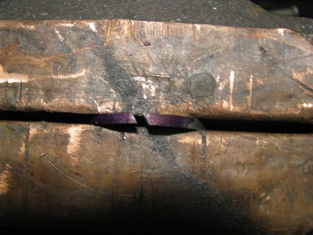
The first job is to split the ring using a small, (junior), hacksaw. The ring should be held as low as possible when the 2 cuts are made. With the first one I held it a little too high and you guessed it, it broke.

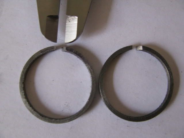
With the ring still held in the vise the “free” gap is filed to size. In this case 0.113”

IMG_1141.jpg


The 2 piston rings have now been successfully gapped.

IMG_1142.jpg


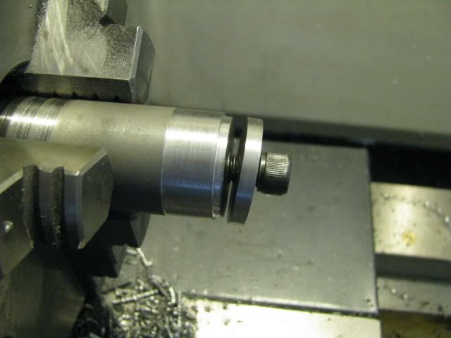
The next task is to make a mandrel to achieve the rings final form and size.

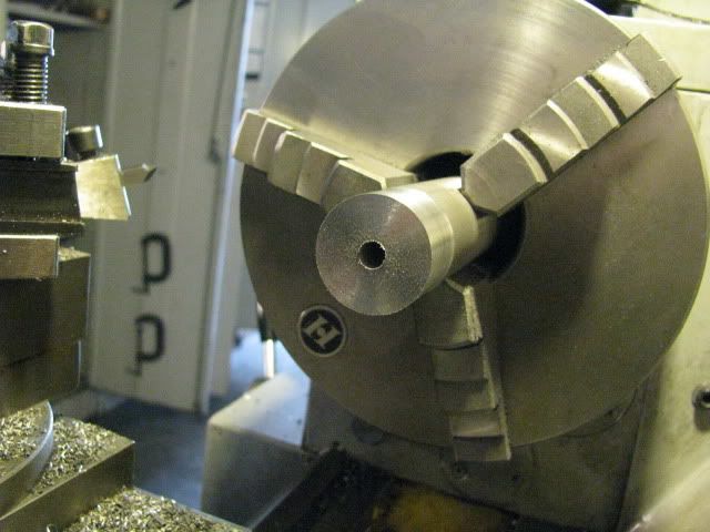
A piece of material is machined to slightly under the finished OD of the ring. This is then drilled to the tapping drill size for a clamping bolt.
Next a section about ¼” wide is parted off from the end and drilled to bolt clearance size.

IMG_1143.jpg


The end of mandrel is now turned down to the final ID of the ring with an axial length a few thousandths of an inch shorter than the ring axial width. Lastly the hole is tapped to take the clamping bolt and you end up with something which looks similar to this.

IMG_1144.jpg


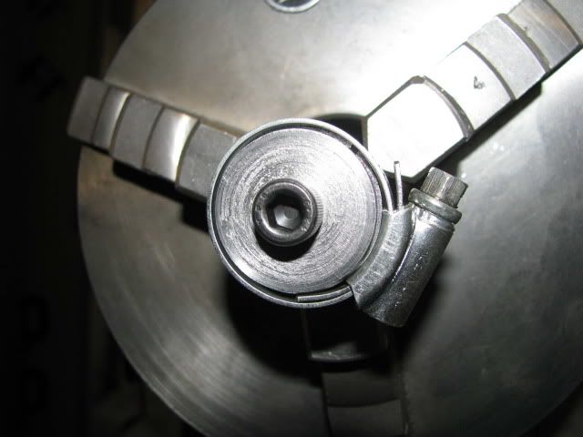
The split ring blank is located on the mandrel and lightly clamped, (finger tight).

IMG_1146.jpg


The ring blank is now compressed onto the mandrel until it is fully located on its’ inner diameter and you cannot rotate it.

Lastly the clamp is fully tightened and the compressor, (fancy name for a jubilee clip), is released.

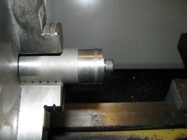
The ring is machined down to the required OD.

IMG_1147.jpg


And Voila - a completed ring with a good amount of tension.

Any questions, I will try and answer them. ??? ??? ??? ??? ???

Testing the rings in the cylinder and on the piston.

IMG_1149.jpg


IMG_1150.jpg


And that's it for this week.

Best Regards
Bob


Latest posts

Back
Top