jgedde
Well-Known Member
- Joined
- Jan 17, 2013
- Messages
- 214
- Reaction score
- 122
So will there ever be a circuit posted on this site that will work AND everyone will agree upon ?? I'm seriously just asking.. Everytime this type of thread gets started it just turns into a "that wont work do it this way" thread.. I can appreciate everyone's take on doing things and I know there are several ways to skin a cat.. But with the electronic knowledge on here it seems everyone could agree on a circuit.. Maybe everyone post thier version of the PERFECT circuit and then put them together and come up with the holy grail of ic circuits.. Thanks..Bill
Bill,
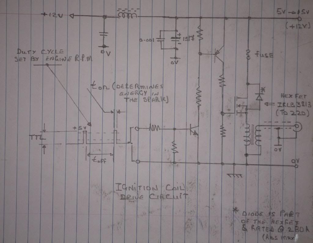
I think Sage's circuit is just that. It's very simple, yet it works and works well. While mine has more protections against power transients and such and lower "standby" power consumption, it is more complicated as a result.
All that said, it holds no advantage over Sage's with regard to its primary purpose... Driving a coil to make a spark and preventing the coil from being stuck on.
So, where are we at? Here's my OPINION FWIW:
If you like soldering up components, or are concerned about power consumption, or want a "Cadillac" circuit, build mine. If you want a good circuit to generate a spark, with "no muss or fuss", build Sage's. You can't go wrong either way.
Bear in mind, though that in Sage's circuit, the LED should not be omitted without fully understanding that the LED and resistor are also being used cleverly as a pullup for the hall sensor - a necessary thing.
Also, either circuit will accept input from a oscillator circuit (or a micro) to make a true multiple spark ignition circuit or to implement your own advance/retard. That's cool stuff on a model engine to be sure!
Now, if you search around the net for model engine ignition circuits, you'll find a few. Some of them are exceedingly bad... I'll hold my tongue about which ones in particular...
John


![DreamPlan Home Design and Landscaping Software Free for Windows [PC Download]](https://m.media-amazon.com/images/I/51kvZH2dVLL._SL500_.jpg)


