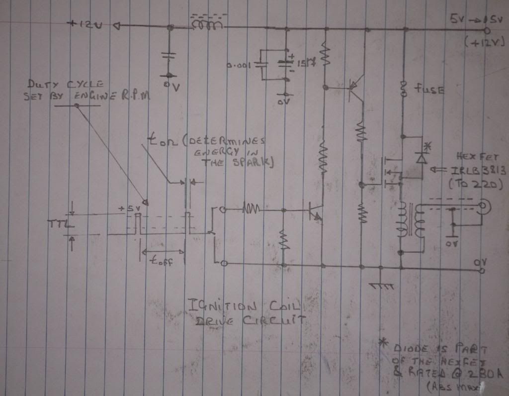
Jerry, I just simulated it in spice. It works, sort of. What happens is this:
1) The gate goes high and turns the FET on.
2) The coil starts to charge a bit, then the fact that the source (the side connected to the coil) goes high, there is insufficient Vgs to keep the FET on.
3) This cycle repeats until the hall untriggers.
4) The frequency is dictated by several things like total gate charge and the time constant of the coil.
The neat thing that happens is you'd get multiple sparks!
The bad thing that happens is sure to blow the FET. The voltage at the top of coil (at the source pin) spikes negative (as would be expected). But, the gate is high. I'm seeing negaive Vgs spikes of 50-60 volts with a 1mH coil. This is absolutely positively going to cause gate rupture in the FET.
If this were a P-channel FET, the story would be different, although your input circuit would have to change a bit.
You can simulate it for yourself using LTSpice. It's a free spice tool put out by Linear Technology and can be downloaded from here:
http://www.linear.com/designtools/software/#LTspice
BTW, I handed the schematic to one of my EE coworkers (a super smart dude) and asked him simply if he thought this would work. He didn't do a spice simulation but predicted a result that matched the simulation I ran!
I really think your idea has merit but needs some tweaks. The MOSFET approach has some distinct advantages and I would love to see it pursued.
I think it needs either a P-channel for the MOSFET and a zener clamp for the gate, or a floating high side gate driver. Another thought would be a small gate drive transformer like the switching power supply guys use. The cool thing with the transformer or floating gate driver is that, inherently, the coil would never be able to get stuck on.
John
How do you like the book I posted


![DreamPlan Home Design and Landscaping Software Free for Windows [PC Download]](https://m.media-amazon.com/images/I/51kvZH2dVLL._SL500_.jpg)


