Ford 300 Inline Six

Home Model Engine Machinist Forum

Help Support Home Model Engine Machinist Forum:

This site may earn a commission from merchant affiliate links, including eBay, Amazon, and others.
The model's rocker cover is pretty similar to the drawn steel original but was machined from a block of 6061 aluminum. A significant difference between them is the original cover attached to the head with seven hex bolts around its perimeter, while the model's cover will be held down with three centrally located studs.

I'd been looking forward to the rocker cover because it was a perfect opportunity to use a new-to-me engraving operation in my CAM software. I've engraved lots of parts using a general purpose 2-d contouring operation to guide a v-cutter over simple stroke fonts. But Sprutcam has a dedicated operation capable of raising or lowering any Windows font using a variety of wall styles.

I hoped to machine the 'powered by Ford' logo that I remembered being in the top of my project truck's rocker cover. But after spending hours working around the cover's filler cap and mounting holes with different fonts, sizes, and spacings, I settled on just 'Ford'.

After a few practice engravings, the cover's exterior machining was pretty straight forward, although its curvy exterior left me with a work-holding problem for the machining of its interior. A wood form, band-sawed with a matching contour, helped spread the clamping forces over the cover's thin (.063") walls. Internal notches were added to the starboard inside edge for additional clearance to the ends of the rocker arms. A pair of 3/64" dowel pins were also added to the head to positively locate the cover.

The cover was painted with Gun Kote's metallic blue - a shade somewhere in between Ford's light and dark blues. Gun Kote is a durable bake-on (325F) resin-based coating that's resistant to gas, oil, and most solvents around my shop. I've used it on small areas on some of my other model engines. With a typical air brushed thickness less than .0005", it typically isn't necessary to mask off tapped holes (except spark plug bores). I only recently discovered the Kote has become available in colors other than black, gray and drab olive.

I originally planned to paint only the rocker cover and then bead blast it away if I didn't like the result. After a few days I was still happy with the cover, and the novelty of a realistically colored engine grew on me, and so I painted the whole thing. - Terry

111.JPG
112.JPG
113.JPG
114.JPG
115.JPG
116.JPG
117.JPG
118.JPG
119.JPG
120.JPG
 
The cover was painted with Gun Kote's metallic blue - a shade somewhere in between Ford's light and dark blues. Gun Kote is a durable bake-on (325F) resin-based coating that's resistant to gas, oil, and most solvents around my shop.

Aw, Terry you nailed it. Looks so good!
I've never used the product but been eyeing it. Just to confirm, did you use the rattle can? And pretty much followed the heat temp/time guidelines?

https://www.brownells.com/gunsmith-...s/gun-kote-oven-cure-gun-finish-prod1150.aspx
Peter,
I've used the rattle can version in the past but have since switched to air brushing. The coating thickness is more easily controlled, runs are less of a problem, and the cans sometime 'spit' out paint and ruin the finish. There are also only a few colors available in rattle can and they're hard to find. I haven't been able to get it (the rattle can version) from Eastwood for a long time now. The manufacturer recommends Alodining aluminum if bead blasting isn't possible, but I've never used it with Alodine. I follow the baking recommendations on their label- one full hour at 325F. I've never had a problem with it chipping or lifting, and it's certainly seen it share of gasoline, oil, and Wd-40 around my shop. A few parts on my motorcycle still look as good as they did when they were painted in 2000. Gun Kote is now also available thru Amazon:

https://www.amazon.com/s?k=gun+kote...ix=gun+kote,aps,193&ref=nb_sb_ss_ts-doa-p_7_8
Terry
 
Last edited:
Wow! That before and after blasting pics of the valve cover lettering really show how much of a difference that process makes to the appearance of the parts.

I am following along very closely as I'm currently part way through building a CNC router and have aspirations to use it to make some cool engine parts. You're doing an amazing job on the engine!

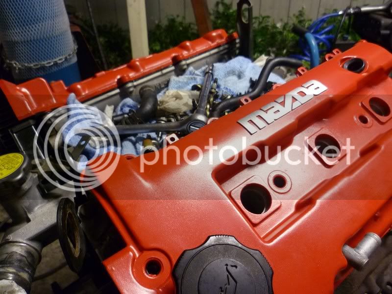
Have you thought about maybe sanding the paint off the FORD lettering on a flat surface? Just a thought, could look pretty nice. I remember doing it to a Mazda I used to have.
2111119.jpg
 
Last edited:
The model's rocker cover is pretty similar to the drawn steel original but was machined from a block of 6061 aluminum. A significant difference between them is the original cover attached to the head with seven hex bolts around its perimeter, while the model's cover will be held down with three centrally located studs.

I'd been looking forward to the rocker cover because it was a perfect opportunity to use a new-to-me engraving operation in my CAM software. I've engraved lots of parts using a general purpose 2-d contouring operation to guide a v-cutter over simple stroke fonts. But Sprutcam has a dedicated operation capable of raising or lowering any Windows font using a variety of wall styles.

I hoped to machine the 'powered by Ford' logo that I remembered being in the top of my project truck's rocker cover. But after spending hours working around the cover's filler cap and mounting holes with different fonts, sizes, and spacings, I settled on just 'Ford'.

After a few practice engravings, the cover's exterior machining was pretty straight forward, although its curvy exterior left me with a work-holding problem for the machining of its interior. A wood form, band-sawed with a matching contour, helped spread the clamping forces over the cover's thin (.063") walls. Internal notches were added to the starboard inside edge for additional clearance to the ends of the rocker arms. A pair of 3/64" dowel pins were also added to the head to positively locate the cover.

The cover was painted with Gun Kote's metallic blue - a shade somewhere in between Ford's light and dark blues. Gun Kote is a durable bake-on (325F) resin-based coating that's resistant to gas, oil, and most solvents around my shop. I've used it on small areas on some of my other model engines. With a typical air brushed thickness less than .0005", it typically isn't necessary to mask off tapped holes (except spark plug bores). I only recently discovered the Kote has become available in colors other than black, gray and drab olive.

I originally planned to paint only the rocker cover and then bead blast it away if I didn't like the result. After a few days I was still happy with the cover, and the novelty of a realistically colored engine grew on me, and so I painted the whole thing. - Terry

View attachment 126891View attachment 126892View attachment 126893View attachment 126894View attachment 126895View attachment 126896View attachment 126897View attachment 126898View attachment 126899View attachment 126900
Man, I’m REALLY looking forward to your video of it running. That’s downright fantastic looking!
 
The poly lock rockers in the model's valve train are a deviation from the single shaft rocker assembly used in the actual engine. Scaling probably squeezed out the shaft supports, and the cover's hold-down studs wound up in their place.

I'm looking forward to machining the rocker arm bodies, but each one requires another five nuisance parts to function. These tiny parts not only require careful machining and multiple setups, but they're the kinds of parts that tend to go missing in the shop. I decided to tackle them first and save the rocker arms as carrots to help get me through the miserable parts.

For starters, the rocker posts were machined from 3/16" drill rod. Each end was drilled and tapped for 2-56 Loctited studs and a hex was machined around their bottom ends. The hold-down studs for the rocker cover are similar and were machined using the same setups.

The rocker shafts were machined from the same rod stock. The first operation was a radial thru-hole for the post. After several tries, I had a production setup on the mill that consistently drilled and reamed the hole through the part's center. A center-drilled milled flat was necessary to start the hole. This flat also became the final contact surface for the poly-lock nut.

After parting off the semi-finished shafts, their ends were finished with a v-drill and blued. These cosmetic touches seemed like a good idea at the time, but they added a lot of extra work for little improvement in appearance.

The poly lock nuts were machined and cold blued to look like the after-market nuts I've seen on full-size engines. The rocker arms rotate on the rocker shafts which are located the rocker studs. Lash is adjusted by turning the nut against the flat on the rocker shaft which sets the clearance of the rocker to the end of the valve stem. The 'poly lock' moniker comes from the grub screw in the top of the nut that locks in this adjustment.

After being drilled and reamed for their shafts, the rocker arm rollers were parted from a length of 5/32" drill rod. The shafts will be modified 1/16" dowel pins once the final lengths are determined - Terry

121.JPG
122.JPG
123.JPG
124.JPG
125.JPG
126.jpg
127.jpg
128.jpg
129.jpg
130.JPG
 
The clearance slots added to the inside of the valve cover allowed some freedom to modify the rocker arm design. My goal was to end up with realistic looking rockers that could be machined in cookie sheet batches. Since there's no top end oil source, I used 7075 for its hardness and wear resistance. Three batches of six rockers were started with the hope of winding up with some spares that could be used to experiment with colored final finishes.

The full shapes of all six rocker bodies, down to their approximate half thicknesses, were machined through the top face of the workpiece. Using a syringe, the troughs left around them were filled with Devcon (flowable) 5-minute epoxy. After an overnight cure, the adhesive kept the parts temporarily attached to the workpiece while their machining was completed through the opposite face of the workpiece. The parts were easily removed after an hour bake at 325F. Stubborn bits of adhesive were easily scraped off the still-hot parts using a sliver of wood.

Machine backlash, tool measurement errors, and edge finder inconsistencies invariably combine to leave seams between oppositely faced machining operations that can add a lot of work to tiny parts. Extra care was taken when setting the work offsets, and the same workpiece corner was used for each pair of operations. I got lucky, and the rockers' seams were on the order of only a thousandth and vanished with bead blasting.

Once freed from their workpieces, the parts were clamped one at a time in a shop-made fixture for the three remaining secondary operations: 1) a hemispherical cavity for the pushrod, 2) a clearance slot for the poly-lock nut, and 3) a clearance notch for the roller.
In order to hold onto the completed rocker arms during bead blasting, I made up some 'lollipop' sticks to protect the two shaft bores from the glass grit. I originally planned to gold anodize the finished parts, but reconsidered after thinking about the problems I'd have to overcome in getting reliable electrical connections to the parts without affecting their finished bores.

Instead, I decided to Alodine them which I hoped would leave leave a similar colored finish. Alodine is used on aluminum as a paint primer or, by itself, as a salt-spray resistant coating. The 'good stuff' is hard to find nowadays because of its chromium health risk, but I was able to purchase a reasonable facsimile from Amazon:

https://www.amazon.com/dp/B0049CDP5W/?tag=skimlinks_replacement-20
After bead blasting, the lollipop'd rocker arms were dipped in NaOH (drain cleaner) for a fifteen second final cleaning, rinsed in water, and then immediately immersed in the Alodine. The 6061 parts I've coated in the past turned golden bronze in just a few minutes, but the zinc in 7075 greatly slowed the process, and the parts came out gray-green. One of the photos shows the colors obtained on test parts after a half hour and two hours in Alodine. I'd have been happier with the half hour test color, but my batch results were inconsistent, and I had to settle for 'army green'. - Terry


131.JPG
132.JPG
133.JPG
134.JPG
135.JPG
136.JPG
137.JPG
138.JPG
139.JPG
140.JPG
 
Last edited:
The drawings call for machining the valve seats directly into the head. This isn't something I normally do, and I didn't want my first attempt to be on a head with so much machining time. Another consideration was that the seats which sit below the surface of the head are so close to the edges of the combustion chambers that none of my seat cutters will fit.

Converting the head to use valve cages wasn't difficult, but did create extra work. Before installing the cages, their seats were manually cut using a piloted seat cutter and then leak checked. Since the intakes are larger than the exhausts, two different size cages were needed. All were machined from 544 phosphorous bronze.

The cages were turned .0015" under their bores in the head for slip fits augmented with 620 Loctite. Five separate operations in a single lathe setup were used to machine their interiors. To begin, a 3/16" 60 degree carbide v-mill was plunged into the end of the blank to rough out the cage's interior and spot drill its guide bore. The guide bore was drilled and reamed after facing the cage to its final length. Finally, a tiny boring bar was used to finish the cage's i.d. and sculpt a filleted port transition

For seat cutters I typically use piloted 45 degree chamber reamers available from Brownells. A shop-made pilot was required to accommodate the tiny valve stem diameters (.093", increased from .078"). The cutter's final TIR measured .0007", but trial seats cut into a few scrap cages appeared to be perfectly uniform under a microscope.

A pair of leak-check valves was then machined to test the cages before they were installed. These test valves were turned using a portion of the code developed for the actual valves which will be turned later on my little Wabeco CNC lathe. Although dimensions can be challenging, it's not at all difficult to turn a valve's key features precisely concentric and end up with brilliantly polished seating surfaces that don't leak. It's been my experience that pristine valves directly off a lathe seldom if ever leak.

The seats, however, are another matter. Even on a lathe, it's more difficult than one might expect to drill a guide bore precisely concentric with a turned seat. A piloted manual seat cutter solves this problem, but it can leave microscopic scratches behind that affect the seal.

These scratches can be easily polished away without lapping the seats to their valves. Typical automotive lapping compounds are too coarse, and they embed into the bronze alloys typically used for model engine valve seats. Combined with poor lapping techniques, an otherwise perfect valve can be quickly destroyed.

After installation, the valves will be checked by pulling vacuums behind them through their associated ports and measuring their leak-down times. I consider a 10-15 second leak-down time measured from 25 inHg to 15 inHg on a Mityvac to be a 'pass'.

The standalone cages were tested with a Mityvac drawing a vacuum through the rear of the cage with the test valve held in place with thumb pressure. A tiny flat milled along the length of the test valve's stem provided the evacuation path.

The measured leak-down times on the uncut seats of valves directly off the lathe were on the order of five seconds which might be good enough to get a multi-cylinder engine started. (Seat seals typically improve in a running engine due the explosive forming effects of combustion.) After cutting a .005" to .007" wide seat with the seat cutter, the leak-down times improved to 10-15 seconds. Only the weight of the cutter was used to apply the cutting force, and the cutter was blown free of chips and lubed with WD-40 before each use.

The leak-down times were typically extended to 25-30 seconds by polishing the seats for 10-15 seconds with extra-fine Timesaver. The Timesaver was mixed with oil and applied using a felt bob rotated by hand. A final 10 second polishing with red rouge on a second felt bob typically extended the time another 5-10 seconds. The final leak-downs ranged from 30-45 seconds. Considering the much smaller volumes of these cages, these leak-down times were comparable to some of my previously best results. - Terry

141.JPG
142.JPG
143.JPG
144.jpg
145.jpg
146.JPG
147.JPG
148.JPG
149.JPG
150.JPG
 
After the Loctite was allowed to cure for a few days, the intake and exhaust ports on the starboard side of the head were drilled and reamed. I tried to not raise burrs inside the cages that might later break free and wind up in the seats, but I ended up with a few anyway. Working through the mouths of the cages with a rifling file would have risked damage to the seats, so I removed them through the ports with a dental pick. The leak-down measurements were repeated to verify the cages hadn't been distorted by drilling nor a seat scratched by the chips. With the test valve in place, the guides were capped and the vacuums pulled through the ports.

I've never cared for the full-size engine's manifold arrangement. The alternating side-by-side intake and exhaust manifold flanges share several of the same mounting bolts. The head bolt clamping forces are divided between the flanges so long as they're exactly the same thickness. When I rebuilt my truck engine, I replaced a leaky cast iron exhaust manifold with a new tubular header but could never get it entirely leak free.

Even with a gasket it will be asking a lot from the model's 2-56 manifold bolts to seal both manifolds, and so a set of thin-wall steel port liners was machined and Loctited inside the ports. The outside ends will slip inside the manifolds and hopefully reduce their tendency to leak. The inside ends were shaped with a Dremel grinder for smooth transitions into the cages. As a bonus, the cages are positively locked inside the head.

Using the spring parameters provided in one of the drawings, I estimated the spring rate to be 8.5 lbs/in and the seat force to be about 1.25 pounds. I attempted to duplicate the seat pressures with a set of springs wound with some .024" diameter stainless steel wire (saltwater fishing leader) that I had on hand. Six active turns around a .190" mandrel resulted in a spring with a .275" o.d. and a .6" length. The wound springs were normalized at 400F for an hour before being tumbled overnight in walnut shells and red rouge. The measured spring rate was 4.5 lbs/in, and the estimated seat force was 1.2 lbs.

A set of spring retainers were machined from 12L14 and cold blued. Commercial e-clips, used as valve locks, will establish the final spring heights and seat pressures. I also added a set of spring cups to keep the springs centered around the guides.

I used my current assembly model to machine a first article valve to verify the seat pressure and to check for clearances and proper operation with the finished valve train components. Minor adjustments to the stem's length and lock groove location were noted for the production valves. The actual seat force measured 1.4 lbs, and yet another leak-down measurement taken. The next step is to machine all the valves and wrap up the head assembly. - Terry


151.JPG
152.JPG
153.JPG
154.JPG
155.JPG
156.JPG
157.JPG
158.JPG
159.JPG
160.JPG
 
Wonderful work as usual!

I bought one of those muzzle crowning chamfer tools from Brownells. My valve cages are 1/2" od and 7/16 id. When I try to use the the tool, holding both the cage and tool in my hands I get a lot of chatter and gnarly looking seats. What is the recommended method to prevent this?

Thanks, John
I hold the cage, mouth up, in my left hand and then insert the cutter into the cage with my right hand. I just let the weight of the cutter exert all the cutting force while I spin the cutter with my right hand. I use a cutting lubricant, usually cutting oil. This time I used WD-40 which I don't think worked quite as well. It's important to blow the chips out of the cutter's flutes before each use so a chip doesn't get wedged between the cutter and cage and gouge the seat.

Don't push on the cutter, you're just trying to put a very tiny seat on the inside edge of the seat. You may be pressing too hard and causing the cutter to dig in. - Terry
 
Back
Top