- Joined
- Dec 2, 2008
- Messages
- 971
- Reaction score
- 9
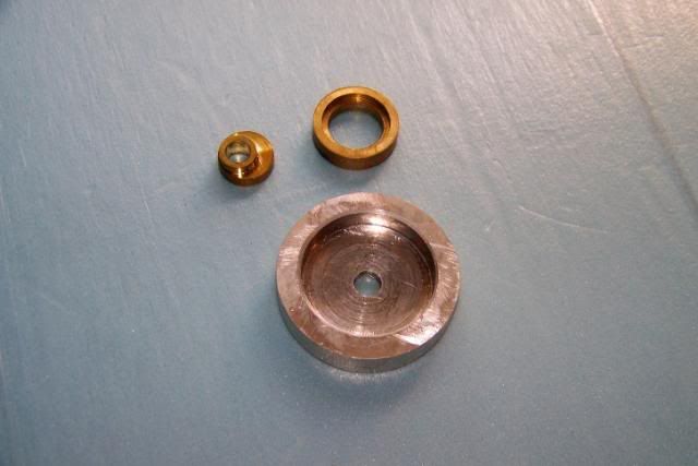
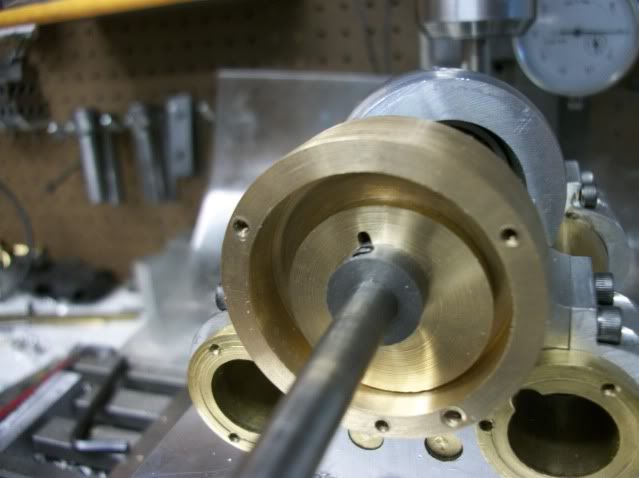
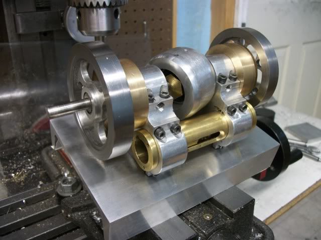
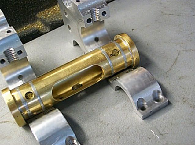
This post is going to be about ball joints (again). I know I have posted on that subject before but every time I revisit the subject something new (to me) is discovered. In the first pic below, are two pistons attached to the dingle arm with ball joints. On the right is a nice looking design proved less than reliable. On the left is the new design that seems much more reliable. Time will tell.
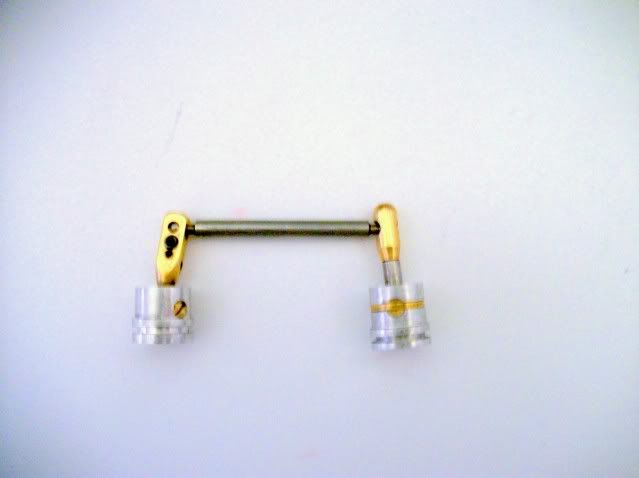
The design on the right is assembled and adjusted with a #8-32 set screw in the top end. The end of the screw has a socket which forms one side of the ball socket in direct contact with the ball. Once assembled, the screw is not accessible or adjustable and under use the relatively course thread of the screw tends to loosen. The new design on the left uses a #2-56 SHCS through the side and does not contact the face of the ball. Since the adjusting pitch is about 75% finer than the screw in the other design, adjustment is more precise and there is little or no tendency of the screw to loosen. And with the screw on the side it is possible to design an access port in the piston skirt and the cylinder wall for fine adjusment and to take up for wear without disassembling the engine.
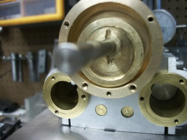
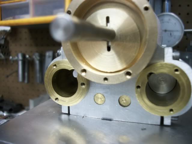
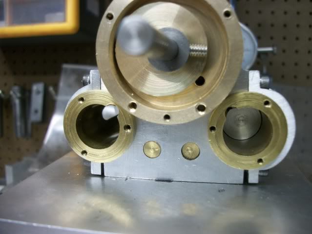
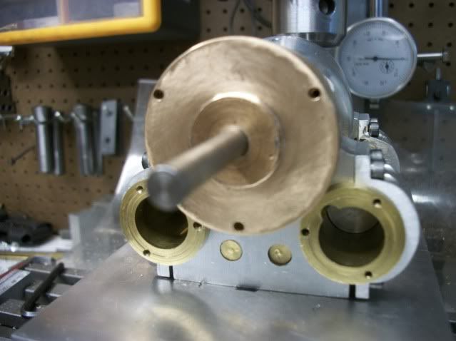
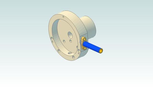
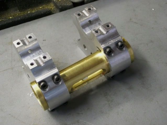
In the second pic, the adjusting screw is visible and to the right is another empty hole in the side of the clamp. This hole is for a jack screw to assist in assembly.
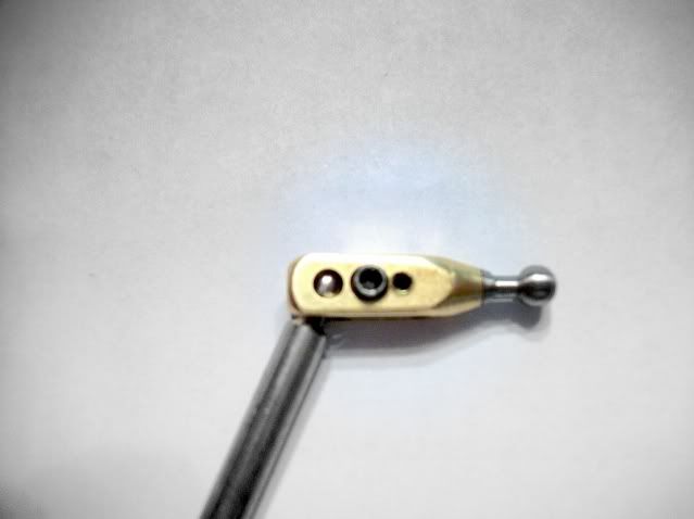
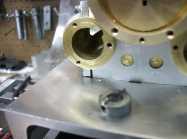
It is used to force the jaws of the clamp apart so that the ball can be inserted without force. Once the ball is in position, the jack screw is backed out and the jaws of the socket close around the ball loosely. The jack screw is then completely remove and placed in the clamp screw hole where it is used to close the socket clamp around the ball untill all backlash is eliminated without adding friction to the joint.
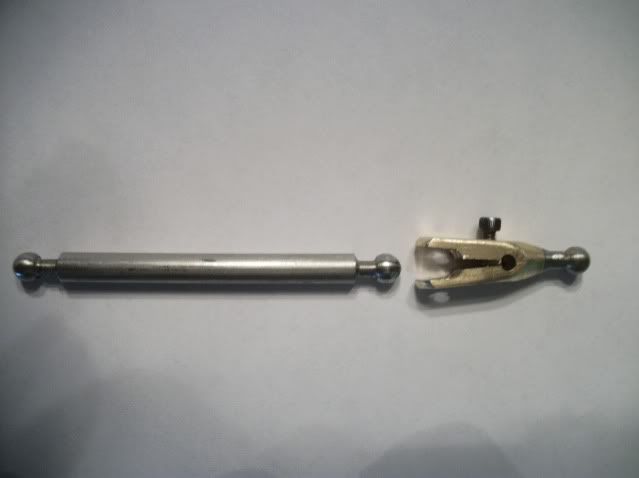
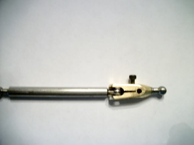
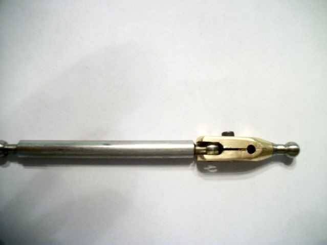
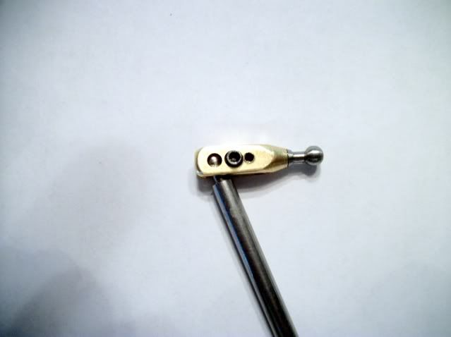
The resulting ball joint is tight with almost no backlash and very little friction. It has good range of movement and is reliable and adjustable.
It is a little clunkier looking and maybe slightly heavier. I don't think the weight difference is enough to affect engine balance and it will be mostly hidden from view.
Now on to other things.
Jerry

The design on the right is assembled and adjusted with a #8-32 set screw in the top end. The end of the screw has a socket which forms one side of the ball socket in direct contact with the ball. Once assembled, the screw is not accessible or adjustable and under use the relatively course thread of the screw tends to loosen. The new design on the left uses a #2-56 SHCS through the side and does not contact the face of the ball. Since the adjusting pitch is about 75% finer than the screw in the other design, adjustment is more precise and there is little or no tendency of the screw to loosen. And with the screw on the side it is possible to design an access port in the piston skirt and the cylinder wall for fine adjusment and to take up for wear without disassembling the engine.
In the second pic, the adjusting screw is visible and to the right is another empty hole in the side of the clamp. This hole is for a jack screw to assist in assembly.

It is used to force the jaws of the clamp apart so that the ball can be inserted without force. Once the ball is in position, the jack screw is backed out and the jaws of the socket close around the ball loosely. The jack screw is then completely remove and placed in the clamp screw hole where it is used to close the socket clamp around the ball untill all backlash is eliminated without adding friction to the joint.


The resulting ball joint is tight with almost no backlash and very little friction. It has good range of movement and is reliable and adjustable.
It is a little clunkier looking and maybe slightly heavier. I don't think the weight difference is enough to affect engine balance and it will be mostly hidden from view.
Now on to other things.
Jerry




![DreamPlan Home Design and Landscaping Software Free for Windows [PC Download]](https://m.media-amazon.com/images/I/51kvZH2dVLL._SL500_.jpg)


![MeshMagic 3D Free 3D Modeling Software [Download]](https://m.media-amazon.com/images/I/B1U+p8ewjGS._SL500_.png)


