Edwards Radial 5 Build

Home Model Engine Machinist Forum

Help Support Home Model Engine Machinist Forum:

This site may earn a commission from merchant affiliate links, including eBay, Amazon, and others.
Brian, I took a look at the Hemingway site and that is a fine-looking grinder, better than anything I've seen elsewhere. I've got a query in to them about the 120 v. motor -- or simply the option of supplying it without a motor at all.

One question about your (again, most excellent) recipe for grinding the Edwards crankshaft...when you refer to surface grinding at verious points, is this something you were able to accomplish with the Hemingway's attachment, or are you in fact guilty of possession of a stand-alone surface-grinder?

And a bonus surprise on the Hemingway site -- they offer a Hall-effect package which, at first glance, seems as though it might be the answer to running this engine on sparks rather than glows, as discussed earlier.

Thanks again for all your help and illumination...

Michael
 
Ditto to Michaels remarks - Steve it is absolutely amazing what you are achieving with that little lathe and no mill. When you have finished I think you should approach HF for an endorsement (for financial gain of course) so that they can show just what can be done with their 7" X 10".
I will be having a two or three break from the work shop as we are travelling to the east coast to catch up with our daughter, son in law and grandkids for Easter (1000 mile drive). This will give me some think time before tackling those heads.
I think I will make a list of the things I have yet to make and post it so that maybe I can get some tips from those that have.

Cheers - Brian :hDe:
 
G'day Steve and all,
Steve your comments about the fit of a 5/16" dowel pin into the BHA57 bearing had me rushing for my bearing also purchased from Boca and try a 5/16" dowel pin into it and indeed it does feel a bit of a loose fit although when the pin and bearing are perfectly parallel there is little or no discernable "slop".
I have made my crankshaft but so far not bothered with the crank pin or fitting the bearing to the master rod as I do not have a press to fit it (next purchase an arbor press).
The bearing I have is an IKO brand BHA57.
Being the worry wart I am I looked up IKO's own specifications for this bearing and they do indeed list a shaft size of 5/16" for it so no error from Boca.
One particular section in the specs. got my attention and this is it pasted.
2 In the case of Shell Type Needle Roller Bearings,
the correct dimensional accuracy is achieved only
after the bearings are press-fitted into the specified
housing bore.
I guess sometimes we just have to decide whether or not to trust these boffins in the design room with their engineering degrees even though most wouldn't know which end to hold a spanner.
Based on this information I think I will still use a 5/16" pin.
What do think you will do and has anyone else had some experience with this? Now I am off to finish the valve rockers.
Picture of crankshaft minus crankpin.
Cheers Brian :rant:

Brian...
As I mentioned earlier I attempted to make a 2 piece crank which was a bust:wall:
I have ordered a 3/4" x 2" x 12" (4140 steel annealed)
I was up most of the morning thinking about it...:eek::eek::eek:
Using my drill press drill out the rough "H" pattern and finish cutting with a hack saw removing the blue sections.
Set up 2 centers, one for the shaft and one for the crank pin.
turn the main shaft first on the lathe and them move to the crank pin centers
and turn.
Cut off the extra material from the prop end.
Set it up in my milling attachment and bring the 3/4" thickness of the throw down to .625
Attach the counter weight and turn to match...
Harden and grind to final dementions.
I have no way to harden and grind so may have to contract this out.
Here is a simple drawing as how I was thinking of doing it.
Could you please step me through how you turned yours up?:confused::confused::confused:
That is if you haven't left on holiday yet...
(Note: I have used my drill press as an arbor press)
Steve

CRANK.png
 
G'day Steve,
I must admit it never occurred to me to machine the crank from a rectangular section piece but in your case it is probably a smart move as you will have a lot less metal to remove with that little lathe.I notice you are using 4140 instead of the specified 4340. The smallest diameter 4340 I could find from Australian suppliers was 4" (by the way where are you located) and I sourced some 2'' round 4340 from Online Metals in Seattle.
To the best of my memory this is how I did mine.
1. Chucked the 2" stock supported with a live center.
2. Turned down the four diameters' required on the crank a few thou. oversize with a carbide tool and then just a couple of a tenths of a thou. oversize with a high speed tool bit (better finish) and then cut thread.
3. Using a ground steel rule and fine carborundum paper polished crank to exact size.
4. Removed and reversed the crank in the chuck and skimmed diameter true and machined thickness a bit oversize to allow finish grinding of the web and clearance boss.
5. Removed the chuck from lathe and mounted on rotary table on mill and trued and centered then drilled and reamed hole for crankpin.
6. Milled web to rectangular dimensions and drilled and tapped holes for counterweight.
7. Remount chuck on lathe and using jig (see photo) and with back gear engaged and slow RPM so that out of balance is not an issue finish grind web to .355 thick using tool post grinder leaving the .625 diameter for the raised clearance boss.
8. Remove crank from jig and mount in chuck and grind the raised clearance boss to 10 thou. above web.
With regards to heat treatment I spoke with a most helpful person at a company in Adelaide and he said that my 4340 was close to Rockwell C35 hardness anyhow and that further heat treatment would almost certainly change the dimensions slightly and would not recommend it. I am confident the crank will be OK as is but I guess the lesson here is heat treat before final dimensions.
I hope this makes some sort of sense to you Steve and seeing what you have already done I know you will come up with a method that suits you equipment.
Remember there is no right way or wrong way just different ways!
In regards to the counterweight see an earlier post and also one to follow to answer some queries from Michael.
PS. I still should be contactable while away.
Cheers - Brian :confused:

turning crankshaft.jpg


crank jig copy.jpg


crank end.jpg
 
Brian, I took a look at the Hemingway site and that is a fine-looking grinder, better than anything I've seen elsewhere. I've got a query in to them about the 120 v. motor -- or simply the option of supplying it without a motor at all.

One question about your (again, most excellent) recipe for grinding the Edwards crankshaft...when you refer to surface grinding at verious points, is this something you were able to accomplish with the Hemingway's attachment, or are you in fact guilty of possession of a stand-alone surface-grinder?

And a bonus surprise on the Hemingway site -- they offer a Hall-effect package which, at first glance, seems as though it might be the answer to running this engine on sparks rather than glows, as discussed earlier.

Thanks again for all your help and illumination...

Michael

Aloha and G'day Michael,

Yes! Guilty as Charged - I was real lucky and managed to pick up this flat bed grinder from a deceased estate for 800 bucks. I don't think it had much use, just a little paint knocked off I suspect from handling. It is very heavy and we lifted it with a hydraulic crane on a tractor onto my trailer and off and into my workshop with an engine crane. It is a great bit of kit - nothing like it to get a smooth precision flat finish.
I used it to do the flat sides on on the counterweight simply for convenience.
Just clamp on the magnetic chuck and grind away. It could have been done with the tool post grinder on the lathe but would have taken longer to set up for grinding true (perhaps holding in a 4 jaw chuck).
Interesting about Hemingway's Hall Effect Ignition. I had a look and it may have possibilities in the future. I nominate you to research and design a spark ignition for the Edwards. Apparently Forests' spark ignition versions developed a bit more HP. Another inovation was a "fan" in the inlet manifold to better distribute fuel to the cylinders. Something to ponder about?
PS. let me know if Hemingway can supply a grinder kit with a 120v motor or whatever. I spent a lot of time researching and came to the conclusion that it is probably the best option available. I am not really all that keen about grinding on a lathe but made a tray to catch most of the grindings and I now cover the lathe bed and as much as possible with alfoil for protection. When finished the alfoil is carefully removed and I clean the lathe with a vacuum cleaner before finally dusting off with compressed air.

Cheers - Brian Thm:

surface grinder copy.jpg
 
Hi Brian
I too have the Edwards plan set but have not done anything with it.
I'm told there was a spark ignition version as well, but Ive never seen one.
Why don't you start a build thread on your Engine, id love to see it :cool:
Hi Anthony
Looking very nice, very nice indeed.
Pete

G'day Pete - I apologise for not responding sooner and thank you for your comments. I somehow overlooked it while communicating with Michael and Steve. Sorry!
This thread has now really come back to life after sitting pretty much idle for 3 1/2 years. Maybe all the new activity will get you fired up and another Edwards Radial underway. I hope so.

Cheers - Brian - me under the hammer *club*
 
Aloha everyone --

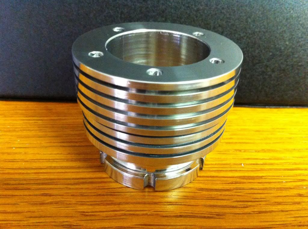
The quest to produce a mid-Pacific Edwards Radial 5 continues -- the cylinder barrels have been duly hacked at, providing my first taste of making parts for this motor in multiples of 5 (everything else so far has been a one-off). So here's one of the barrels...


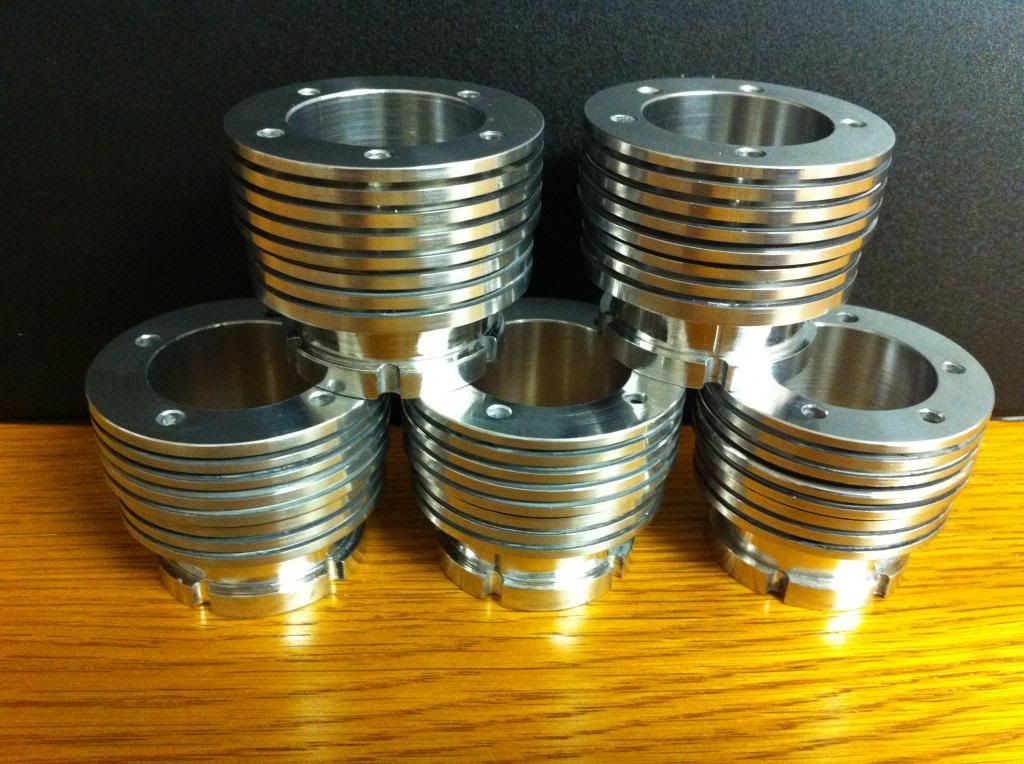
...and here are five of them doing acrobatics...


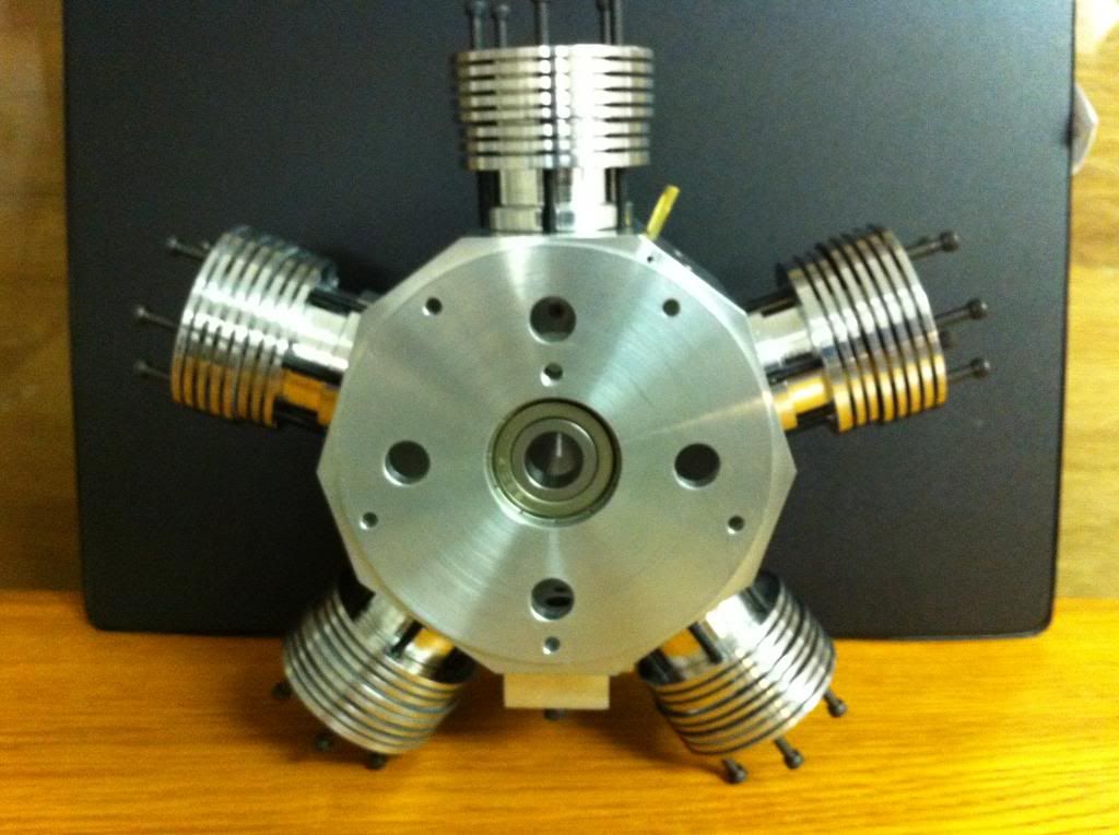
...and here are the same five clinging to the crankcase, wondering what happens next...


CrankcasewithBarrelsfromfront_zps3396c9b1.jpg


I imagine the next attempt will be to finish off the cam cover, which will begin with a respectful copy of Brian's fly-cutter to carve out the recesses for the lifters.

I've begun thinking that I'd really like to build some sort of engine cradle to put this engine together on, rather than just having it loose on the bench. I'd hate to see it go bouncing across the floor after all this. So that will probably come next, and it'll give me some breathing space before taking on the crankshaft and piston assembly, which has been keeping me awake nights. Especially since it now seems that building a toolpost grinder is going to have to be part of that process.

I've been keeping careful track of my machining hours on this project (first time I've done that, and now I know why) and have racked up 82 so far...but the head-time (daydreaming and figuring while doing something else I'm actually paid to do) must be at least ten times that.

With the several engines being built out there has anyone given any thought to actually strapping the finished motor into an aeroplane and flying it? I'd be most interested in anyone's thoughts about an appropriate model idea. I'm thinking so far about a biplane with about a nine-foot span, but I'm open to anything. (Except an ARF, RTF, or anything in the way of a too-detailed scale model. I've seen pictures of the plane Mr. Edwards built for the original (or was it the other way around?), but not too much else.

What a fun project this is.

Michael T
 
Last edited:
Aloha everyone --

The quest to produce a mid-Pacific Edwards Radial 5 continues -- the cylinder barrels have been duly hacked at, providing my first taste of making parts for this motor in multiples of 5 (everything else so far has been a one-off). So here's one of the barrels...

Fat-finnedcylinderbarrel_zpsd4c1874b.jpg


...and here are five of them doing acrobatics...

BarrelsBottoms_zpsc93e8e2e.jpg


...and here are the same five clinging to the crankcase, wondering what happens next...


CrankcasewithBarrelsfromfront_zps3396c9b1.jpg


I imagine the next attempt will be to finish off the cam cover, which will begin with a respectful copy of Brian's fly-cutter to carve out the recesses for the lifters.

I've begun thinking that I'd really like to build some sort of engine cradle to put this engine together on, rather than just having it loose on the bench. I'd hate to see it go bouncing across the floor after all this. So that will probably come next, and it'll give me some breathing space before taking on the crankshaft and piston assembly, which has been keeping me awake nights. Especially since it now seems that building a toolpost grinder is going to have to be part of that process.

I've been keeping careful track of my machining hours on this project (first time I've done that, and now I know why) and have racked up 82 so far...but the head-time (daydreaming and figuring while doing something else I'm actually paid to do) must be at least ten times that.

With the several engines being built out there has anyone given any thought to actually strapping the finished motor into an aeroplane and flying it? I'd be most interested in anyone's thoughts about an appropriate model idea. I'm thinking so far about a biplane with about a nine-foot span, but I'm open to anything. (Except an ARF, RTF, or anything in the way of a too-detailed scale model. I've seen pictures of the plane Mr. Edwards built for the original (or was it the other way around?), but not too much else.

What a fun project this is.

Michael T

Very nice work Michael!
I did make the flycutter that Brian posted but these past few days have been a bust!:wall:
Cindy printed out the cam cover for me and the measurements were misprinted...:mad:
Instead of the undercut of 0.200 depth of the cut it came out as 0.400!:fan:
Also I had the cam cover mounted on my rotary with one 1/4-28 cap screw to the center and it let loose and spun on the table ruining the cam housing even further.
OK, Will start over and attach it better to the rotary table this time around.
I have also attempted to make 3 cylinders so far but 2 were unusable as the fin spacing was off...
The best one may be usable...
My problem here is getting the fin spacing equal.
I may purchase a pair of DRO's to help with both the cylinder fin spacing and depth of the under cut on the cam cover...
Steve
 
Hi Steve, and thanks for the feedback!

Sorry to hear you've been having a rough week of it. I've certainly had some of those...and then, just as I'm thinking of taking up knitting instead, something magic happens and I get sucked right back in.

I must say the toughest part of the cylinder barrels, for me, was getting the bore within specs for its whole length. As far as getting the fins consistent, I just relied on the width of the parting tool (ground to 0.040") and using the top cross-slide to back it up that much, plus the width of the fins themselves. Which, by the way, I took to be 0.080"...firstly out of mis-reading the drawing, but then I carried on that way just because it looked better, and at that point in the cylinder I think there'll be enough surface area for cooling anyway. Certainly, when I get to doing the heads, (which is where the main heat is, I guess) they'll have much thinner and more numerous fins.

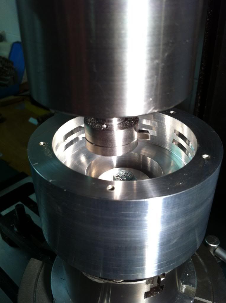
The cam cover really is a challenge, isn't it? Your account of your 1/4"x28 cap screw letting go at an embarassing moment is a bit disturbing -- the setup I just began to use last night also relies on a 1/4" bolt (though it's 20 tpi, and a hex) through a clearance hole in a short plug turned to fit the 0.890" ID, and screwed tightly into a hex nut gripped in a 3-jaw. Here's a pic of it the last time I saw it:

Drillingholesformountingscrews_zps5c15a2c0.jpg


As you can tell I'm just drilling the holes for the mounting screws so far, but now I'm getting a bit twitched about how it'll hold up when I start whacking away with my newly-hatched flycutter. It certainly seems solid enough, but if it's not you may hear the bang all the way from Oz. :hDe:

All best,

Michael
 
I built a 2 cylinder boxer that used Edwards head bolt pattern. If I had to do it over again I would increase that base circle to give some more room between the bolts and cylinder for head gasket sealing surface.
I did not make any attempt to fin the cylinders according to his plans. I left a good margin at the top and threaded and bolted directly to the cylinder, and used a 6 bolt pattern for an expanded bottom flange to mate with the engine casing.
I did not really intend to copy his design, it started out as a cad exercise to determine the Edwards valve seat area, as it bisects a conical combustion surface. Next thing I knew I had drawn an entire engine around it, and dared myself to build it. :)
 
G'day Michael, Steve and all.
As you can see I am now back on line up in Newcastle on the east coast.
Sorry to hear of your bust with the cam cover Steve - work needs to be mounted as securely and rigidly as possible and we've all made measurement errors. I hope the next one works better for you. Please keep posting.
Mike those barrels look great. At the rate you are going you are going to finish way ahead of me. I purchased a really neat parting tool and holder from the USA that takes a 40 thou. parting blade and allows you to get really close to your work and was also great for parting off the piston rings. It came from a small company and I can't remember the name but can look it up when I get home and also take a photo if you are interested.
I should have given the dimensions of the fly cutter but I am pretty sure that the shaft was 1/2" and the head 1" dia. which only left 1/4" of the 1/8" squ. tool bit protruding.
It looks like you mount your chuck on the rotary table much the same as I do.
When I undercut the cam follower grooves the tool really sizzled - no thumping and banging so hope it works the same for you. The last thing I want is to give a bum steer.
Photo cutting slots - can't see much for the chips.

Cheers Brian :toilet:

cam follower slots copy.jpg
 
Just to reassure you, Brian, that the flycutter worked like a dream. Or at least, it has so far. I had to stop work after nine recesses last night because the noise was beginning to disturb some of the neighbors in the building where I have my shop (I share the building with a couple of artists' studios, a Korean church, a bordello, and an insurance agent. As you might imagine, the insurance agent is the biggest problem). Once the tenth recess is successfully excavated I'll suck out the swarf and take a pic.

Best.

Michael T

Interesting mix Michael - at least you can brush up on things, cleanse the soul,insure against busts or ------------ no! not going down that path. - Brian
 
Here are the pictures of my cylinders...
The 1st. one is useless but for the second, I started cutting the cooling fins at the full 2" diameter.
I still have enough "meat" to re-cut the fins on that one.
I too have a small taper in the cylinders where the liner will slide in.
I will tackle this with my cylinder hone.
The #3 to the right is fairly good but will order enough 2" to make 6 more...
The largest bit I have to bore them is a 3/4" but I am going to order a 15/16" and 1" bit.
That will get me large enough with very little clean-up with my boring bar...
Maybe that will give me less of a taper...
I think I have figured out a way to space the fins...
I will make 2 .040 spacers, glue then together with one longer than the other...
Cut one groove move over insert the spacer in that groove and set the tool up against and cut the next...
I had an idea of making a fin tool that has 2 cutters .040 with an .040 space between...
That would give my spacing:confused:
I ordered a slitting saw blade 1/8" x 1-1/2" and made an arbor for it...
My lathe is so small that I was getting too much chatter and thumping by using the fly cutter.
It was shaking the gib screws loose!:confused:
The 1/8" slitting saw should be more easy my lathe.:D
As I said I had my cam cover mounted with 1, 1/4-28 screw through the middle which wasn't enough.
I only have a 3" rotary so I will make up 2 brackets that will slide in the T slot groove.
Thread them for screws and clamp the cam cover to that...
Maybe that will work...
I also found an .040 cut-off tool on ebay and may purchase it...
I am not a pro and my rejects are building up in the scrap pile! LOL!:rant:
Steve

cyl.jpg


saw.jpg
 
Since you don't have a DRO, you can use a DI with a magnet to move the carriage the required spacing for the fins. On my first lathe there was no DRO, but we had a "Mighty Mag" holder that secures the DI along the ways. With the DI plunger depressed against the saddle, zero it, and then use the needle to move the carriage the needed distance. You can get the holder and magnet on eBay for less than $30. Or make your own holder.
 
  • Like
Reactions: xjs
Gentlemen --

So far so good with the cam cover, though I'm acutely aware that the more hours I put into it the madder I'm going to be with myself if I make an error and bust it. It's at the point where I'll sit and stare at it for ten minutes before removing the slightest amount of metal, even after checking all the numbers twice and doing a half-dozen mental rehearsals.

And then I have to remind myself I'm doing this for fun.

In that spirit, hang in there with those cylinders, Steve...what you've done so far is just amazing and you're going to be the proud poppa of five killer barrels in just a little while I have no doubt.

Anyway here's the all-thanks-to-Brian flycutter with ten lifter recesses under its belt...breathing a bit heavily but none the worse for wear...


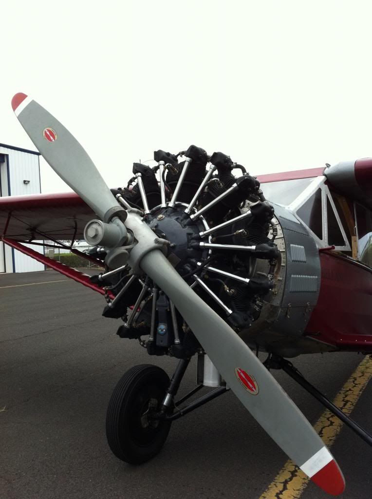
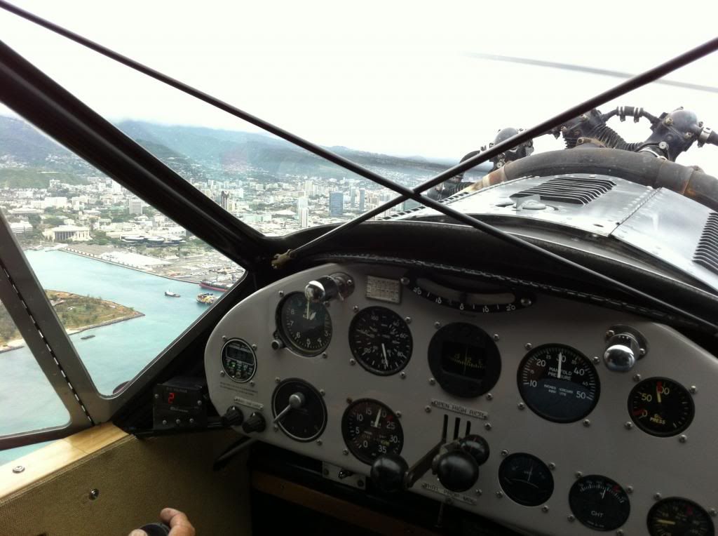
The cover is set up now for drilling the holes around the outside radius for the lifters themselves. Though that'll have to wait for tomorrow, I'm playing hooky from the shop today...a very unusual opportunity presented itself and I just got back from being hauled around the skies over Oahu by a real, live, honest-to-god radial engine...a nine-cylinder Pratt and Whitney, powering a 1929 Bellanca. It's the first-ever aircraft of Hawaiian Airlines, since sold, crashed, sunk, re-built, re-purchased and now fullly restored. Here it is on the ground:


...and, here's what it looks like from the rear when it's hauling you around.


But what I wish I could share with you is what it SOUNDS like. Probably you've had more experience with the real thing than I have, I'm coming late to this. But nothing, nothing on this earth, is as thrilling (to me) as the sound of a radial at full roar. It's just marvellous, majestic, magical.

Building even a baby one from scratch, as we're doing, is an act of devotion.

I just don't understand what people see in football.
 
Last edited:
Gentlemen --

So far so good with the cam cover, though I'm acutely aware that the more hours I put into it the madder I'm going to be with myself if I make an error and bust it. It's at the point where I'll sit and stare at it for ten minutes before removing the slightest amount of metal, even after checking all the numbers twice and doing a half-dozen mental rehearsals.

And then I have to remind myself I'm doing this for fun.

In that spirit, hang in there with those cylinders, Steve...what you've done so far is just amazing and you're going to be the proud poppa of five killer barrels in just a little while I have no doubt.

Anyway here's the all-thanks-to-Brian flycutter with ten lifter recesses under its belt...breathing a bit heavily but none the worse for wear...

Picture018_zpseff36085.jpg


The cover is set up now for drilling the holes around the outside radius for the lifters themselves. Though that'll have to wait for tomorrow, I'm playing hooky from the shop today...a very unusual opportunity presented itself and I just got back from being hauled around the skies over Oahu by a real, live, honest-to-god radial engine...a nine-cylinder Pratt and Whitney, powering a 1929 Bellanca. It's the first-ever aircraft of Hawaiian Airlines, since sold, crashed, sunk, re-built, re-purchased and now fullly restored. Here it is on the ground:

Picture021_zps8f8379b1.jpg


...and, here's what it looks like from the rear when it's hauling you around.

Picture027_zps6146e219.jpg


But what I wish I could share with you is what it SOUNDS like. Probably you've had more experience with the real thing than I have, I'm coming late to this. But nothing, nothing on this earth, is as thrilling (to me) as the sound of a radial at full roar. It's just marvellous, majestic, magical.

Building even a baby one from scratch, as we're doing, is an act of devotion.

I just don't understand what people see in football.


What a thrill. That's GREAT!
 
G'day Steve, I am following your build with interest and as I am currently 1000 miles from my own workshop I have time to fill in " in other peoples workshops". I must admit I am at a bit of a loss to understand your issues spacing the barrel fins. Using a .040" parting tool why can't you advance .040" using the compound (top slide) and cut to the specified depth with the cross slide. I am not at all familiar with your lathe but did download the operating manual from HF and it did not say how the dials were calibrated other than to say "work tolerance .005".
As for turning a taper in barrels have you turned a test bar to see if your lathe turns parallel? - and yes I agree the slitting saw will be a much better option for you and your equipment than the fly cutter.
Hang in there for when you are finished it will be all the more satisfying for doing it on the machinery you have.

Cheers - Brian :bow:
 
G'day Mike, - whew! I am as relieved as you that the fly cutter worked and what an unreal experience to actually fly in that beautiful radial engined plane. And yes - nothing but nothing sounds like a radial, I am sure that is one of the main reasons I am building one.I have flown over the "Big Island" in a light aircraft but unfortunately not radial powered. There are some guys here in Australia that manufacture new radial engines for aircraft (or a chopper motocycle if you are an American). Google Rotec Radial. On a sadder note one of our local residents who had a 80% scale Spitfire and was often seen buzzing the town crashed at an air show in Adelaide a week ago and was killed.
While I am here at our daughters place I have time the study the plans for the heads and work out how I am going to tackle them when I return home. That should add some stress to the holiday.

Cheers - Brian :idea:
 
Since you don't have a DRO, you can use a DI with a magnet to move the carriage the required spacing for the fins. On my first lathe there was no DRO, but we had a "Mighty Mag" holder that secures the DI along the ways. With the DI plunger depressed against the saddle, zero it, and then use the needle to move the carriage the needed distance. You can get the holder and magnet on eBay for less than $30. Or make your own holder.

Thanks kvom...
I do have a DI and a cheap-O magnetic base I use for centering...
The base is not so good as with the adjustments tight it still has a tendency to move around...
I had planed on beefing it up to hold a firm position.
I will attempt to fix it and try this...
Thinks for the idea...
As for the scales behind the hand wheels on the compound and cross slide, they are not so good...
What are your thoughts of making this 2 prong cut-off or fining tool?

Steve

di.jpg


fin tool.png
 

Latest posts

Back
Top