Edwards Radial 5 Build

Home Model Engine Machinist Forum

Help Support Home Model Engine Machinist Forum:

This site may earn a commission from merchant affiliate links, including eBay, Amazon, and others.
Hi Brian --

Great to hear from you, and especially your reassurance on the cam issue. Been giving me nightmares, that...visions of finishing this project but with all the valves just sitting there, fast asleep...

You're way ahead of me it seems, I've just been at this project for a couple of months...here's the story so far:
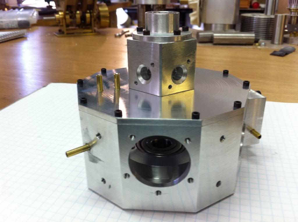


The oil pump assembly is also done, and I hope to be nibbling away at the cam cover this weekend, as long as some proper-sized slitting saws arrive in time. I've also been taking pics fairly frequently, and I'll try to organize a little w-i-p series over the next few days. Would love to see yours too.

Also can't wait to hear of your experience with the cam issue. A lot of potential discussion points come to mind, actually.

All best...

Michael T
 
Last edited:
G'day Michael,Ron and others.
Michael I managed to catch the image of your crankcase and manifold.
For some reason the image is now gone - removed but looked like great work.
I hope this goes OK as I am still learning my way around this site and I don't have a handy 10 year old to help me.
Anyhow this is how I attacked the cam.
1. Machined the blank as per plan (60 year old Hercus 9" lathe - Aussie made Southbend clone) from 4340 steel (tough stuff).
2. Removed chuck from lathe and mounted on 6" rotary table.
3. Mount rotary table on mill and check with dial gauge to make sure there is no run out over 360deg. and then centre in the mill so that measurements can be taken on a radius.
4. Using a 5/8" X 3/16" woodruff key cutter I removed the required amount of material from the start and finish points of the cam lobes as per plan.
5. The cam lobes were then cut a degree at a time as per the chart increasing the lift when cutting up the lobe and decreasing going down the other side of the lobe. This may sound tedious but only a tiny amount of material is removed at a time and it is not as bad as it might seem.
6. When completed you have came lobes consisting of tiny serrations. To remove and polish out the serrations I used 600 wet and dry carborundum paper wrapped around a ground steel rule lubricated with kerosine and finish polished with 1200 paper. Because the difference from one serration to the other is so small this does not take long at all.
I hope this makes some sort of sense and I will now have a go at uploading some images which I hope makes things a bit clearer.
Michael you mentioned you were working on the cam cover and are waiting for some slitting saws. Are they for cutting the slots for the cam followers?
For this task I made a simple fly cutter which worked a treat. If interested let me know and I will photograph it.
Cheers all. :wall:

_DSC2775 copy.jpg


_DSC2883 copy.jpg


_DSC2885 copy.jpg


_DSC2774 copy.jpg
 
Hi Michael and all Forest Edwards Radial enthusiasts.
I have been poking around this site for a long time and have bitten the bullet and joined.
I have been building an Edwards radial for about two years and have completed most major parts except the heads. They are next.
The cam was not the hassle I thought it would be and I would be happy to communicate with you on this (and anything else) Michael.
Once I become more familiar with the site I could add some photos if anyone is interested. (most components and machining operation have been photographed)

Cheers all - Brian in South Australia:fan:

Hello Brian...
I just finished the crankcase and working on the cam...
Oli pump is finished...Waiting on a 1/8" keyway cutter to finish up the cear case...
Please post pictures for all to see please...

Steve
 
Aloha Fans of Edwardian Radials --

-- and Brian, many thanks for the pics and narrative of your cam-carving. Most elegant and helpful. Now my dread has been replaced by hopeful anticipation.

Yes, the slitting saw I mentioned was for the cam-cavities in the cover, but your fly-cutter idea makes a lot of sense. Clearly I have a lot to learn. Neither the slitting saw nor your e-mail arrived before Friday evening, though, so I started hacking away instead at the cylinder barrels as my weekend project.

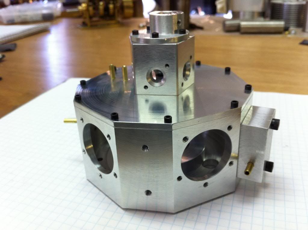
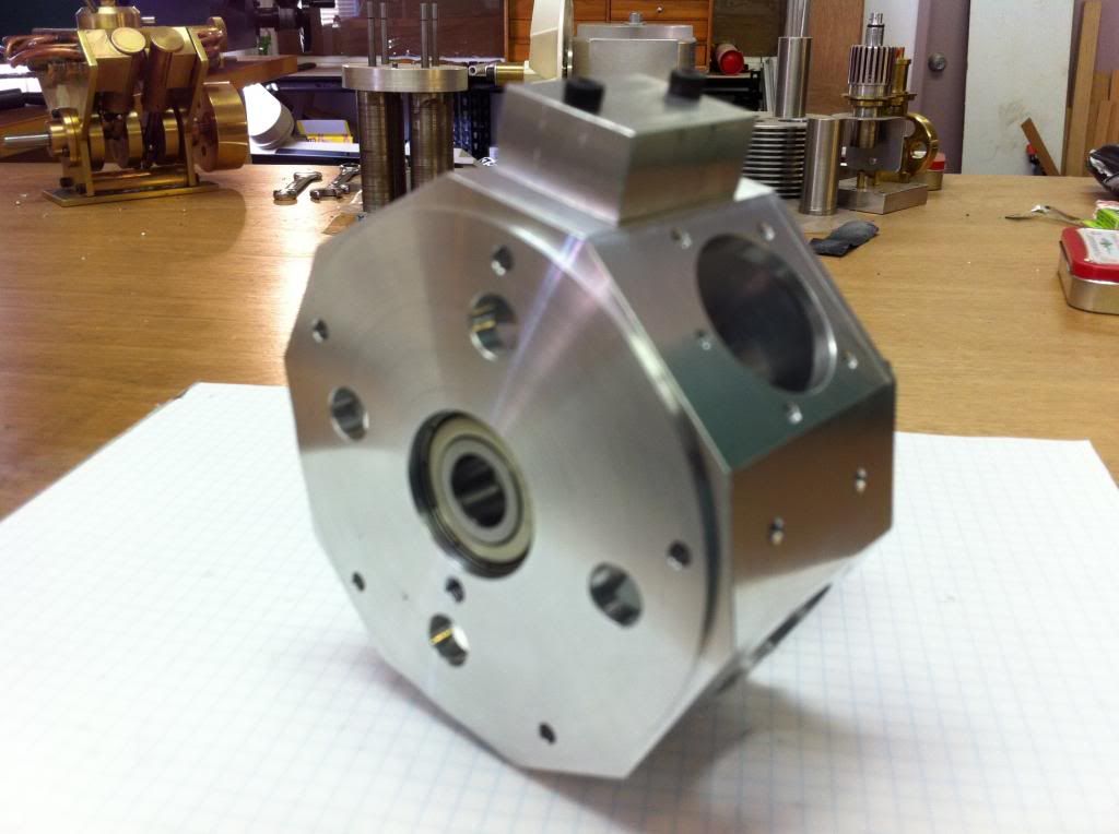
Sorry the pic I posted vanished...apparently my rummaging-around in the Photobucket yesterday afternoon upset something. This whole e-thing has me flummoxed most of the time. Let's try it again:

PartialCrankcaseassembly1_zpsae0619ed.jpg

PartialCrankcaseassembly4_zpsc1905046.jpg

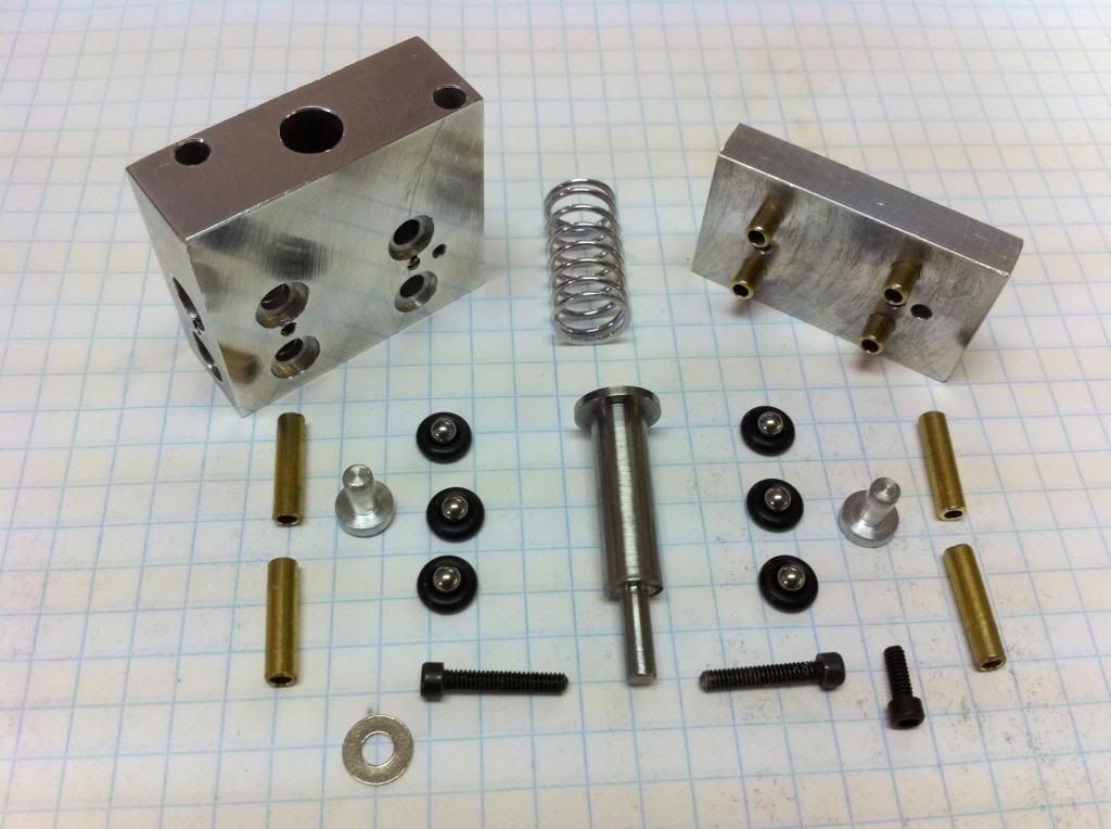
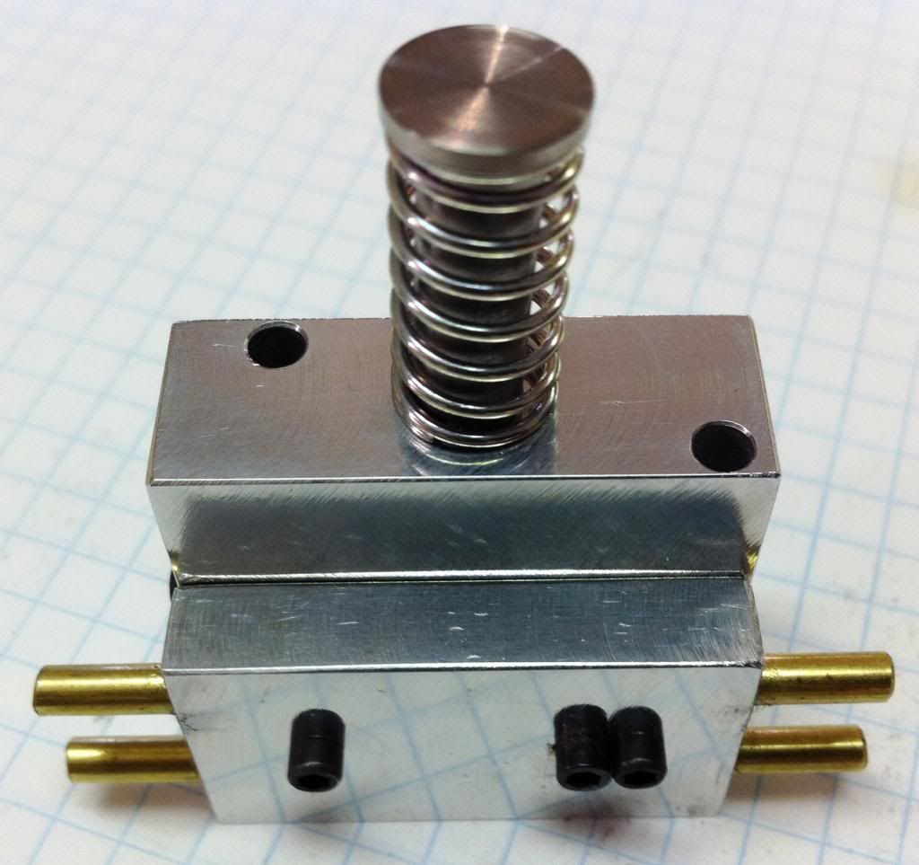
....and, if this is working so far, here are a couple of oil pump pics...one in pieces, one assembled:
Pre-assembledOilPump_zps858ae912.jpg


AssembledOilPump_zps71155cb3.jpg


Before anyone asks...the third capscrew on the front of the pump conceals a broken tap. Shameless, I know. And asymetrical. I'll probably go back and make a new pump body. But not till I've made that cam.

Michael T
 
G'day again Michael, Steve, Ron and all,
I now realize I should have joined HMEM long ago - what a great way to communicate and exchange ideas with people involved in the same or similar projects.
Great stuff Michael and amazing you have done all of that in a couple of months.You are obviously much more experienced than me and can work much faster. This is actually my first ever engine and I spend more time thinking about how to do something than actually doing it. It has also been a major incentive in purchasing much more equipment to do the tasks. No doubt they will be also put to good use in future projects.
I initially looked into purchasing a key way cutter to do the cam follower slots but could not find one the right size hence the reason for making the fly cutter.
The 1/8" square HSS steel bit is adjustable in the milled slot and clamped in place with the cap. Also a picture of the engine so far.
I have currently been working on the valve rockers (no CNC) and they are probably the fussiest part to make so far and are finished apart from machining the top angles (photo's later).
Michael in the background of one of your photo's is what appears to be a brass V4 or twin engine. What is it?
Cheers all- Brian in a currently hot and humid South Australia*beer*

_DSC2778 copy.jpg


_DSC3259 copy.jpg


_DSC3260 copy.jpg


_DSC3261 copy.jpg


_DSC3263 copy.jpg
 
Hi Brian
I too have the Edwards plan set but have not done anything with it.
I'm told there was a spark ignition version as well, but Ive never seen one.
Why don't you start a build thread on your Engine, id love to see it :cool:
Hi Anthony
Looking very nice, very nice indeed.
Pete
 
Beautiful pictures, Brian. Let me join the chorus clamoring for you to start a build thread! And if this is your first engine I'm really curious to see your second and third...a Merlin V-12? A Saturn V booster?

The engine you asked about is a V-4 "wobbler", designed for marine use by a Scandinavian chap, Gustaffson I think. It's designed in metric but I scaled it up a bit by making a millimeter count for a sixteenth. Satisfying project, but not too practical for an airplane, which is what I'm hoping to do with the Edwards radial. With apologies for including a steam engine in a radial IC thread, here's a pic:

SV4assembly001_zps1f3c0829.jpg


Back to the Edwards: I haven't made any of the crankshaft gear yet and I've been wondering about the link and main rods...is the bare aluminium really up to the task of being the bearing surface, or does anyone else think that maybe a bronze insert at each end might be a good idea?

I'm also curious to know if anyone has had any luck with finding or developing a spark ignition mod for this engine, as Pete mentioned. I know that Mr. Edwards himself made a few sparked models, but I don't know if he ever released the design (as he did so generously with the engine itself!).

Michael
 
That's a real neat looking engine Michael - looks like something that could power a "Time Machine" in a 1940's sci-fi movie and no a Merlin or SaturnV
booster are not in my plans but did consider a jet turbine.
I have shelved that idea for now as I would probably burn down the workshop.
Now back to the Edwards, I must admit that it had crossed my mind as to whether bronze bushes may be better than the piston pins and big ends running on the aluminium but apparently Forests' engines had a good reputation for reliability and one would think any issues would have shown up in the 30 odd engines he manufactured.
I believe that that the British twin Triumph Tiger 100 motorcycles of about the 1960's era ran their aluminium alloy conrods direct to the crankshaft without using any slippers or bearing rollers so it may not be all bad.
Does anyone out there have any thoughts on this?
Michael, in the Edwards parts list an OS piston pin part#10893 is listed but this is discontinued and no longer available. I am using an OS piston pin part#44606000 available from Omni Models in Champaign Ill.
This is the same length with teflon end caps and is .5mm - 20thou. smaller in diameter. I don't think this will have any impact.
How does one start a build thread and what format do you think it take?
I have attached some photo's of the piston pin and master rod with conrods attached and pistons just sittin there. ( seems I am already on the way to a build thread)
Cheers - Brian*discussion*

_DSC3266 copy.jpg


_DSC3267 copy.jpg


_DSC3269 copy.jpg
 
Aloha Fans of Edwardian Radials --

-- and Brian, many thanks for the pics and narrative of your cam-carving. Most elegant and helpful. Now my dread has been replaced by hopeful anticipation.

Yes, the slitting saw I mentioned was for the cam-cavities in the cover, but your fly-cutter idea makes a lot of sense. Clearly I have a lot to learn. Neither the slitting saw nor your e-mail arrived before Friday evening, though, so I started hacking away instead at the cylinder barrels as my weekend project.

Sorry the pic I posted vanished...apparently my rummaging-around in the Photobucket yesterday afternoon upset something. This whole e-thing has me flummoxed most of the time. Let's try it again:

PartialCrankcaseassembly1_zpsae0619ed.jpg

PartialCrankcaseassembly4_zpsc1905046.jpg

....and, if this is working so far, here are a couple of oil pump pics...one in pieces, one assembled:
Pre-assembledOilPump_zps858ae912.jpg


AssembledOilPump_zps71155cb3.jpg


Before anyone asks...the third capscrew on the front of the pump conceals a broken tap. Shameless, I know. And asymetrical. I'll probably go back and make a new pump body. But not till I've made that cam.

Michael T

That is very nice work Michael!
I tried out my pump yesterday to see if it would pump with some caster oil and it did like a charm!
Just wish I had a decent camera to take pictures with...
I have a piece of 4140 on the lathe right now and turning down for the cam.
So far I have the crankcase finished with exception of drilling and taping for the cylinder screws...Oil pump is finished...cam housing is bored to the right demensions and waiting on the keyway cutter to arrive.
I ordered a piece 3/4" x 2" x 12" of 4340 for the crank.
I attempted to make a 3 piece crank from some pre-hardened 4140 but it is in the scrap pile now...

Steve
 
G'day again Michael, Steve, Ron and all,
I now realize I should have joined HMEM long ago - what a great way to communicate and exchange ideas with people involved in the same or similar projects.
Great stuff Michael and amazing you have done all of that in a couple of months.You are obviously much more experienced than me and can work much faster. This is actually my first ever engine and I spend more time thinking about how to do something than actually doing it. It has also been a major incentive in purchasing much more equipment to do the tasks. No doubt they will be also put to good use in future projects.
I initially looked into purchasing a key way cutter to do the cam follower slots but could not find one the right size hence the reason for making the fly cutter.
The 1/8" square HSS steel bit is adjustable in the milled slot and clamped in place with the cap. Also a picture of the engine so far.
I have currently been working on the valve rockers (no CNC) and they are probably the fussiest part to make so far and are finished apart from machining the top angles (photo's later).
Michael in the background of one of your photo's is what appears to be a brass V4 or twin engine. What is it?
Cheers all- Brian in a currently hot and humid South Australia*beer*

Excellent work Brian! Beautiful!!!th_wav
 
:confused::confused::confused:
FYI...
The rod needle bearing JH57-oh-40 was replaced with SCH57 from Boca Bearing and states .312 ID...
It is not! It is 8MM.
A 5/16" dowel pin fits too loosely into the bearing.
I had some 8MM stainless rod left over from another project and it fits perfectly.

Steve
 
G'day Steve and all,
Steve your comments about the fit of a 5/16" dowel pin into the BHA57 bearing had me rushing for my bearing also purchased from Boca and try a 5/16" dowel pin into it and indeed it does feel a bit of a loose fit although when the pin and bearing are perfectly parallel there is little or no discernable "slop".
I have made my crankshaft but so far not bothered with the crank pin or fitting the bearing to the master rod as I do not have a press to fit it (next purchase an arbor press).
The bearing I have is an IKO brand BHA57.
Being the worry wart I am I looked up IKO's own specifications for this bearing and they do indeed list a shaft size of 5/16" for it so no error from Boca.
One particular section in the specs. got my attention and this is it pasted.
2 In the case of Shell Type Needle Roller Bearings,
the correct dimensional accuracy is achieved only
after the bearings are press-fitted into the specified
housing bore.
I guess sometimes we just have to decide whether or not to trust these boffins in the design room with their engineering degrees even though most wouldn't know which end to hold a spanner.
Based on this information I think I will still use a 5/16" pin.
What do think you will do and has anyone else had some experience with this? Now I am off to finish the valve rockers.
Picture of crankshaft minus crankpin.
Cheers Brian :rant:

crankshaft copy.jpg
 
Brian and Steve, thanks so much for the pointers on pins and bearings. I'm sure you've saved me no end of gnashing, not to mention precious time. And your thoughts on the link rod bearing surfaces, Brian, are much appreciated. I had no idea that the rods on the old Triumphs "went commando" and, you're right, it seems almost heretical to question the judgment of Mr. Edwards.

And may I say again (then I promise to stop gushing) how useful, even inspirational, I'm finding the photographs of your work. Something to aspire to. (The photography, as well as the superb craftsmanship).

I was struck by something you said a couple of posts back, about how you spend more time thinking about doing than actually doing. I think that's a big part of the attraction of this business for me. Getting lost in a good drawing, trying to figure out the setups and challenges (and pitfalls) ahead of time, and creating parts in my head is something I can carry around with me all the time, and adds tremendously to the pleasure gotten from the precious few hours I actually get to spend in the shop.

And, of course, head-time produces much less wear and tear on the machinery.

Glad you liked my little adventure in steampunk, the wobbling V-4. Bending those copper pipes was a pain, but satisfying, and I guess some sort of rehearsal for the intake tubes of the Edwards.

As it turned out there was infuriatingly little time available for the shop this weekend, though there are now five little rough-bored and drilled pieces of aluminium lurking on the bench that I hope will grow up to be nice shiny cylinder barrels in another few days.

Then, by golly, I'm going to make me one of them fly-cutters.

Just because.

Michael
 
Thank you for the appreciative remarks Michael, it's nice as some of our friends come around and just say what are you doing that for and what are you going to do with it. I tell them it keeps the brain active and may stave off the onset of "Old Timers Disease". Sometimes I wonder though when I look at some of the jigs I made a while back and can't figure out what they were for. Oh well!
I take the photo's in one of those collapsable soft boxes - no harsh flash.
Yes! you were correct about a tool post grinder being used on the crankshaft.
It was particularly useful to remove metal from the end of the crankshaft and leave the raised 10 thou. clearance boss. I just turned the end of a piece 1/2" ground stainless steel shaft to fit through the crankpin hole, threaded it and clamped up tight with a machined washer and nut and mounted in the lathe chuck. Then using a cup stone on the tool post grinder finished to required dimension.
I also used the grinder to do the half circles on the counter weight - first roughly removed metal with a hacksaw and bench grinder and then ground one side of the counter weight on a surface grinder. The next part was to turn a shaft with a thin boss the diameter of the half circle and soft solder it to the counter weight. It was then possible to mount in the lathe chuck and finish grind by oscillating the chuck through 180deg. by hand using a drive belt - repeat for other side then surface grind both flat sides to dimension.
If you can't follow my description and want photo's let me know.
I purchased the grinder as a kit of unfinished castings and metal stock from Hemingway Kits in the UK - exceptional service and only took an unbelievable three days to arrive.
The end result is a very nice grinder and quite easy to machine - only thing is it came with a 240v motor where you guys are 120v but they may well also supply with a 120v motor.
The photo with sparks is grinding a cam follower.
And YIPPEE! - today I finished the valve rockers - still need a little hand work knocking off the sharp edges but generally I am pleased with them.
Very tedious work though particularly the way I did them - no CNC.
Cheers - Brian woohoo1

TP grinder:lathe copy.jpg


TP grinder.jpg


grinding cam follower.jpg


rocker copy.jpg
 
G'day Steve and all,
Steve your comments about the fit of a 5/16" dowel pin into the BHA57 bearing had me rushing for my bearing also purchased from Boca and try a 5/16" dowel pin into it and indeed it does feel a bit of a loose fit although when the pin and bearing are perfectly parallel there is little or no discernable "slop".
I have made my crankshaft but so far not bothered with the crank pin or fitting the bearing to the master rod as I do not have a press to fit it (next purchase an arbor press).
The bearing I have is an IKO brand BHA57.
Being the worry wart I am I looked up IKO's own specifications for this bearing and they do indeed list a shaft size of 5/16" for it so no error from Boca.
One particular section in the specs. got my attention and this is it pasted.
2 In the case of Shell Type Needle Roller Bearings,
the correct dimensional accuracy is achieved only
after the bearings are press-fitted into the specified
housing bore.
I guess sometimes we just have to decide whether or not to trust these boffins in the design room with their engineering degrees even though most wouldn't know which end to hold a spanner.
Based on this information I think I will still use a 5/16" pin.
What do think you will do and has anyone else had some experience with this? Now I am off to finish the valve rockers.
Picture of crankshaft minus crankpin.
Cheers Brian :rant:

Brian...
I found my bearing on ebay and was listed as a IKO BHA57...
I received a no name bearing evidently made in China!
It is an SCH 57 and the 5/16" dowel pin is too loose in the bearings...
I may have to buy another bearing directly from Boca...
8MM shaft has just a slight amount of movement and not without wobbling it.
The 5/16" pin has at least .004" of movement.
Finished the rear cover today but messed up on the 2-56 screw holes! :fan:
Drilled for the tap too large...:wall:
SO... I ordered some 4-40 button head screws 1/4" long...
Went ahead and taped for 4-40.

Steve
 
G'day Steve and all,
Steve your comments about the fit of a 5/16" dowel pin into the BHA57 bearing had me rushing for my bearing also purchased from Boca and try a 5/16" dowel pin into it and indeed it does feel a bit of a loose fit although when the pin and bearing are perfectly parallel there is little or no discernable "slop".
I have made my crankshaft but so far not bothered with the crank pin or fitting the bearing to the master rod as I do not have a press to fit it (next purchase an arbor press).
The bearing I have is an IKO brand BHA57.
Being the worry wart I am I looked up IKO's own specifications for this bearing and they do indeed list a shaft size of 5/16" for it so no error from Boca.
One particular section in the specs. got my attention and this is it pasted.
2 In the case of Shell Type Needle Roller Bearings,
the correct dimensional accuracy is achieved only
after the bearings are press-fitted into the specified
housing bore.
I guess sometimes we just have to decide whether or not to trust these boffins in the design room with their engineering degrees even though most wouldn't know which end to hold a spanner.
Based on this information I think I will still use a 5/16" pin.
What do think you will do and has anyone else had some experience with this? Now I am off to finish the valve rockers.
Picture of crankshaft minus crankpin.
Cheers Brian :rant:

Very nice Brian!!!Thm:Thm:Thm:Thm:
 
Well thought I would post a picture of my progress...
Cheap-O cameraand on dial-up::rant:
Crank case and rear cover are finished (with exception of taping for the 4-40 cylinder screws) along with the oil pump.
Cam housing, Waiting on the keyway cutter to arrive.
Once I cut for the lifters I will add the taper.
Working with a 7X10 mini HF lathe and attached a 3" rotary table to the cross slide.
Also have the simple milling attachment made from a 3" angle block and 1-1/2" milling vice.;D
An X2 is on my wish list!

Steve

ED 1.jpg
 
Great stuff Steve! And all on a 7" lathe too!! (I needed that kick in the pants since seeing the pic of Brian's luvly 60-year old machine, an Aussie clone of a South Bend nine-incher, I think he said. I've spent a couple of years trying to domesticate a Chinese 9x20 and was coming down with Ironmongery Envy. You fixed that nicely!)

Thanks for the tips on piston pins, Brian...I've gone ahead and ordered a handful from Omni...though I may have to save a few more boxtops before going for the toolpost grinder. That's a great-looking setup.

Michael
 

Latest posts

Back
Top