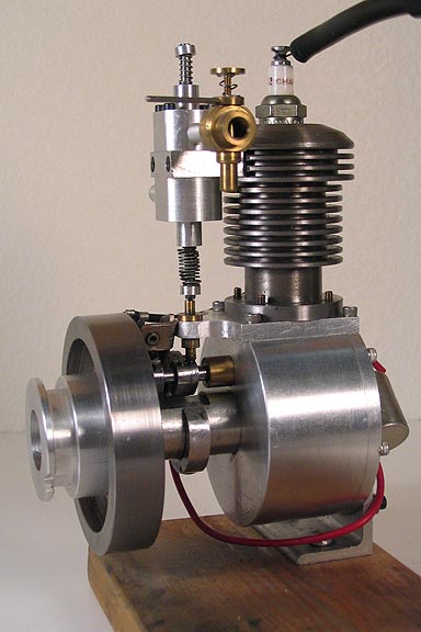
My, it doesn't take long for a guy to slip to page two. I think that's a good sign. Lots of folks building!
This post will show how the main bearing supports are made. Quite a bit of roundy round work in these.
Starting with two aluminum pieces that had been squared up in one setting, three guide holes are drilled
and reamed. The pieces are clamped together to satisfy my paranoia. I want the holes in each piece
to be really well lined up, as two pairs of holes will become running bores.
The third hole, more or less in the middle, is for R/T jig purposes.
Once the holes are drilled, the pieces can be separated and I can proceed with the twirly table work.
Similar to how the arms were made, I need to know where to stop the odd radii that make up the
shape of these things, so the first cuts are the relief that form the bosses for the bearings.
After the bosses are cut on this side, the centering jig hole is put on center on the R/T, and this radius
can be cut through the piece. You can see where this radius ends at the upper bearing boss. It doesn't
matter where the other end of the radius ends, as long as it goes past the part that will become the
straight part of main bearing arm.
Hard to explain what this piece looks like at this point, but it will become clear pretty quick. It will seem
quick, in the pics, at least. Actual time for the first of these two pieces is about six hours. That's "Dean
time". Even slower than real time.
'Bout now, you may be wondering "What are those big gobs of metal holding this mess down?". I
know. I need to make more hold down clamps for my shop!
The second radius that forms part of the support for the upper bearing is cut the same way as the first
one. The X feed is cranked in for the proper width and the cutter offset, and it's in position.
The prints don't give exact dimensions for this slot, but the start and stop points can be figured using
certain datum points. One is at the center of the eye, and one at the far edge of the work piece.
Datum(s) are often the kind of things that are left up to the builder, and in most cases could be a
number of features on a piece. I chose the upper edge in this picture, along with the short slot I had
milled in that edge earlier. The hole centers are given, and if they're put where they belong, will also
serve as datum points.
Sometimes a print will have a line going to a surface calling out a datum. They guy who drew them is
telling you to use that point as a reference for other measurements.
Once those two radii are milled in, I can start cutting out the straight pieces. Since the piece is on the
R/T, and has been cranked round to a few different positions, the piece isn't square, so the first step is
to use a 1-2-3 block against the far edge to get it square to the spindle. I just put the block against the
edge, and ran it up against the headstock, rotating the table back and forth until it was squared up. If
any of the features milled off that reference edge needed to hold a certain tolerance, like if cutting a
mounting surface, the 1-2-3 block wouldn't do. That edge would need to be dialed in properly with a
DTI.
While I had the piece squared up, I went ahead and cut the other bits that amount to perpendicular
lines. Again, locating what goes where using the slot at the blue arrow, and the edge at the red line.
Now the ends of the two slots are connected, and the middle falls out. There is no way to know this
angle, and it's not called out in the print, but since the end points of the radius and straight slot are cut
in, it's kind of a no brainer, (which is right up my alley).
After this cut, the mill table is cranked back to cut the slot that goes from my short datum slot to the
outer radius of the upper boss.
With all that stuff cut out, just have to get rid of the material that's holding the scrap to the piece.
Nothing was cut completely off up to this point in order to leave me with plenty of clamping options.
Back on the pins for the eyes, (bearing bores, actually), and the radii around the bosses are cut, letting
the waste fall away.
Although there is still about a half hour of milling to be done to clean it up, and lots of filing, this is it for
today. I have another one to make yet. When that one is done, and I get these cleaned up, I'll have a
pic to show, and then on to another part. Maybe something in the lathe to clear my head.
Thanks for having a look in.
Dean


