Hello Ved, When I was young I used to play with toys which created a lot of enjoyment. At this stage of life I am creating toys, much better quality and they work. I also feel very creative. So what if you look at them as toys. It is what they mean to me that matters. Norm
You are using an out of date browser. It may not display this or other websites correctly.
You should upgrade or use an alternative browser.
You should upgrade or use an alternative browser.
Double acting Double Oscillator
- Thread starter Brian Rupnow
- Start date

Help Support Home Model Engine Machinist Forum:
This site may earn a commission from merchant affiliate
links, including eBay, Amazon, and others.
"Come on over baby--A whole lot a hoggin going on---" This morning I am turning my 2" diameter cast iron into rectangular cast iron. For some reason my suppler doesn't stock any cast iron flatbar, so this is what I have to do for material to make my cylinders from. Nothing alarmingly difficult, but a lot of cranking. The cylinder bodies are only 2.6" long, but then I need another inch to hold them in the chuck to work on them.
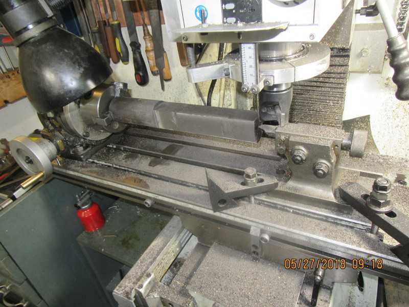

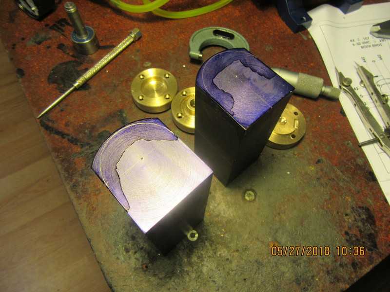
In this shot you can see the two cylinders parted off from the main stock, with one end machined "square" and the finished profile marked out in layout die. The next job will be to set the cylinders up in the four jaw chuck and to drill and ream the bores out to 1" diameter.

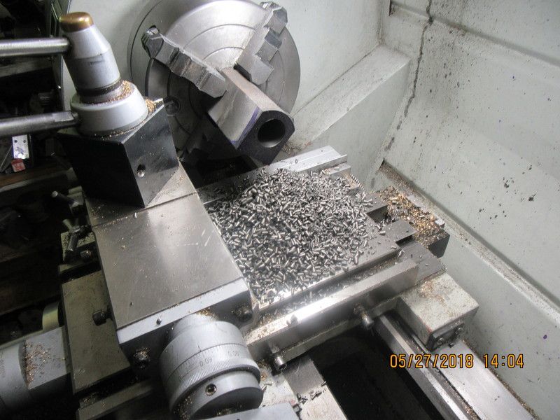
I paid $25 for that length of round cast iron. There has to be at least $5 worth of it in the pile of chips left after boring one cylinder out to 1" diameter. Tomorrow morning when I do the other cylinder, there will be another pile equally big from it.

Okay--First end of first cylinder tapped and air passage machined. Now it's going to be "repeat 3 more times and pray to the machining Gods that we don't bust a tap." I tried one end cap on just to be really really sure, and everything seems to be fitting okay.
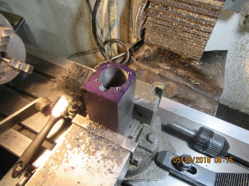

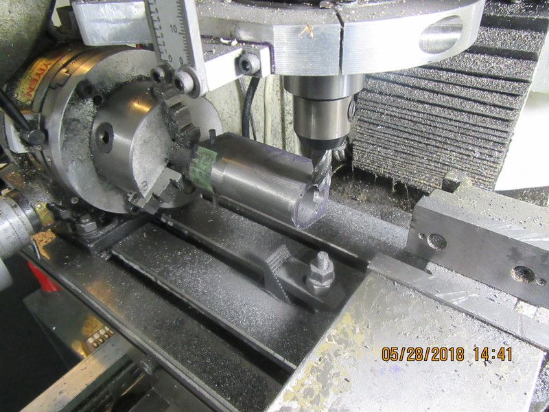
And that, gentlemen, is the way I machine the radius on the outside of the cylinders. You have to look close, but what you see is the cylinder, mounted on a 1" diameter round rod, which is held in the 3 jaw chuck on my rotary table. A half inch end mill is mounted directly over the center of the round bar, and lowered until it is just "kissing" the top of the cylinder, then a little more until it is cutting a full 1/2" wide path but very shallow. Then I take a full length "pass" left to right or vice-versa under the milling cutter. My mill has "stops" on it that I can adjust to limit table travel in the X axis, and I set them so that I don't move the jaws of the chuck under my milling cutter in one direction and just clear of the cylinder in the other direction. My rotary table moves 4 degrees with every full turn of the handle. I advance the rotary table clockwise half a turn, then take a full length pass under the cutting tool. My machine is rigid enough to climb mill, so at the end of one pass I unlock the rotary table, turn the handle half a turn, lock the table and then crank the table in the other direction. After what seems to be about a thousand passes, the cylinder will have turned 90 degrees. Then you crank the rotary table back to its original position and repeat everything, only this time turning the rotary table counterclockwise half a turn between cuts to put the radius on the other side. Don't be confused by the milling vice setting there. It isn't doing anything related to what I'm doing.

Last edited:

$415.08
DM14 Engine Build Kit, Metal Engine Build Model Great Metal Material for Engineer for Factory
Easoger Official

$156.90 ($1.40 / oz)
Replacement Combustion Chamber Kit, Burnham V8 and V8H, 1-6 Sec, 108136-01, 1129
Lynn Manufacturing

$104.99
Sunnytech Hot Air Stirling Engine Motor Steam Heat Education Model Toy Kit M16-CF
stirlingtechonline

$649.00
$699.00
FoxAlien Masuter Pro CNC Router Machine, Upgraded 3-Axis Engraving All-Metal Milling Machine for Wood Acrylic MDF Nylon Carving Cutting
FoxAlien Official

$39.99
$49.99
Sunnytech Low Temperature Stirling Engine Motor Steam Heat Education Model Toy Kit For mechanical skills (LT001)
stirlingtechonline

$109.99
AmTech300 - Boiler Treatment Professional Strength (Rust Inhibitor For Outdoor Wood Boilers)
Alternative Heating & Supplies

$188.98
TM NEXDYNAMI RE41157 Water Pump Compatible With/Replacement For/John Deere 6200 7400 6300 6600 6500 6400 7220 7600 7200 RE41157
VIVID MARKET CORPORATION
![DreamPlan Home Design and Landscaping Software Free for Windows [PC Download]](https://m.media-amazon.com/images/I/51kvZH2dVLL._SL500_.jpg)
$0.00
DreamPlan Home Design and Landscaping Software Free for Windows [PC Download]
Amazon.com Services LLC

$55.69
Amana Tool - 46280 CNC 2D & 3D Carving 6.2 Deg Tapered Angle Ball Tip x 1/32 Dia x 1/64
Routerbitworld

$15.99 ($0.05 / Count)
$18.99 ($0.06 / Count)
HongWay 300pcs 2 Inches Sanding Discs Pad Kit for Drill Sanding Grinder Rotary Tools with Backer Plate Shank and Soft Foam Buffering Pad, Sandpapers Includes 60-3000 Grit
HongWay US

$45.99
Sunnytech Mini Hot Air Stirling Engine Motor Model Educational Toy Kits Electricity HA001
stirlingtechonline

$94.99
$109.99
AHS Woodmaster 4400 Maintenance Kit for Outdoor Wood Boiler Treatment
Alternative Heating & Supplies

$190.00
$254.99
Genmitsu CNC 3018-PRO Router Kit GRBL Control 3 Axis Plastic Acrylic PCB PVC Wood Carving Milling Engraving Machine, XYZ Working Area 300x180x45mm
SainSmart Official
- Joined
- Sep 2, 2011
- Messages
- 1,380
- Reaction score
- 370
looking good. subscribing to this thread to follow along.
Anatol
Well-Known Member
Hi, Brian. At very low speed, say about the 30 rpm mark with no load, the the lack of balance might well show, but at that sort of speed I would think variations in friction and leakage would have just as much of an effect on smooth running. At a normal low speed, I think you would be better off at 90° especially with o-rings on the pistons: the torque will be much more constant with four small power pulses instead of two big ones. At higher speed (the bits become blurry at 200-250 rpm) there would indeed be a bit less vibration at 180°, though there would still be a rocking couple. 180° is very abnormal for a double-acting twin - with good reason?
Charles
your response brings up a matter I was wondering about. What is the difference, mechanically, in terms of torque etc, between a V twin configuration with cranks at 180 deg, and an H twin with cranks 90 deg out of phase?
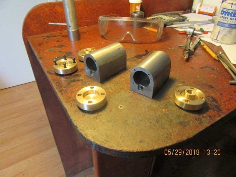
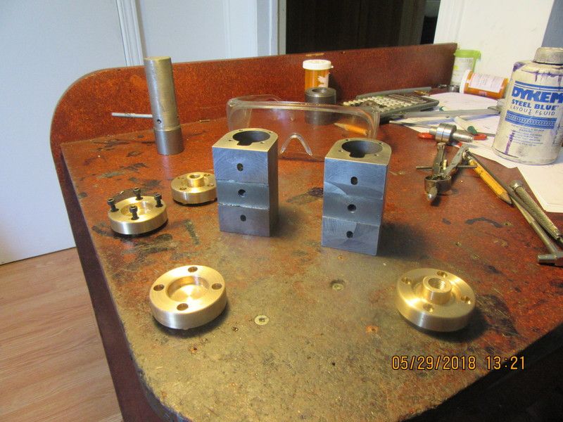
So, there we have two cylinders finished. Both of the cast iron cylinders have to spend a bit of time with some 150 grit emery paper to get rid of any unwanted machining marks, but the machining itself is finished. Sixteen #6-32 tapped holes in and no broken tap, big sigh of relief.


- Joined
- Sep 2, 2011
- Messages
- 1,380
- Reaction score
- 370
Brian, is it an optical illusion / machine marks I see or is the middle of the cylinders where the pivot bolt would go machined slightly deeper than the friction / valve port hole surfaces are? if so what a great idea. reduced friction and only the valve ports are rubbing, which really would be the only area that needs to be rubbing for sealing.
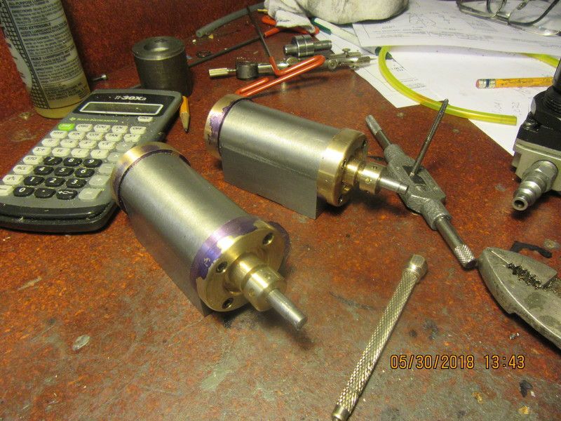
Yes Werowance, you're seeing it right. The middle is relieved 0.030". There is no need to have material there. This morning I machined the piston rod glands, fitted everything, and made the first assembly of the cylinders. These are "long stroke" cylinders, and Jeez they look huge. 1" bore x 1 3/4" stroke. Those are not the real piston rods you see sticking out the end of the cylinders. They are just some "dummy rods" to aid in keeping everything lined up for assembly. I still have to profile the inward side of the cylinder caps, but had to assemble things to this stage and "mark out" where the fillet ends, as I don't want the fillet to continue around the caps where they meet the cylinder bodies on the lower half.

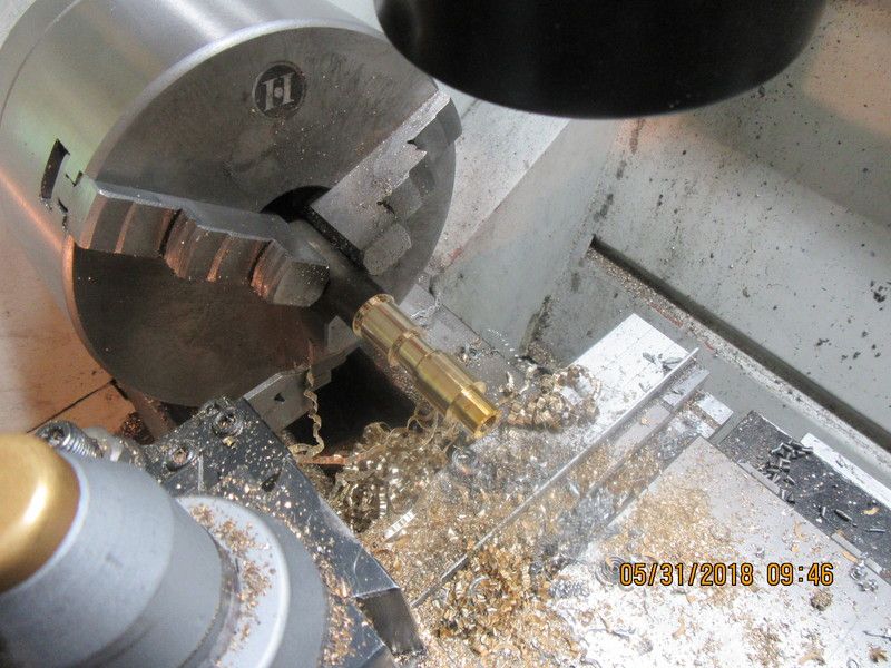
This morning I'm making piston rod ends. They are not terribly hard to make, but the sequence of machining operations is quite important. In this shot the diameters have been turned onto the end of a stick of 5/8" round bronze. The one closest to the end has been reamed for a 1/4" dia. piston rod. The rod is mostly hidden inside the chuck and hollow headstock shaft. Now I will move operations over to the rotary table on the mill and put the flats on both sides and the 5/16" holes for the crank-pin in. Then back to the lathe where I can part off the one closest to the end.
This morning I'm making piston rod ends. They are not terribly hard to make, but the sequence of machining operations is quite important. In this shot the diameters have been turned onto the end of a stick of 5/8" round bronze. The one closest to the end has been reamed for a 1/4" dia. piston rod. The rod is mostly hidden inside the chuck and hollow headstock shaft. Now I will move operations over to the rotary table on the mill and put the flats on both sides and the 5/16" holes for the crank-pin in. Then back to the lathe where I can part off the one closest to the end.

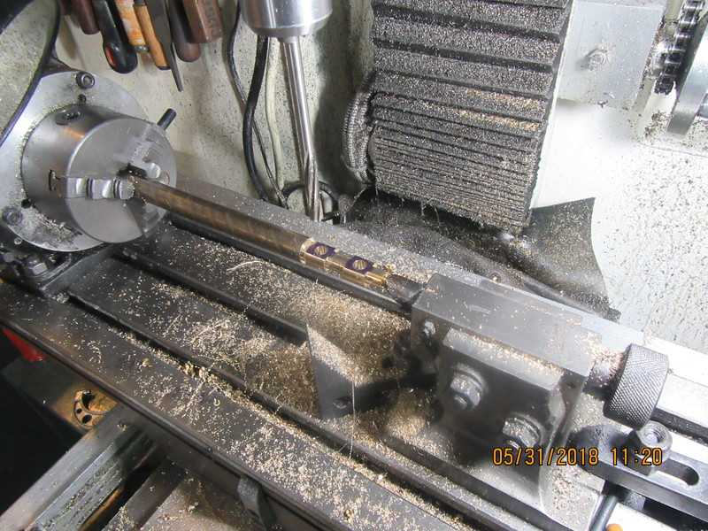
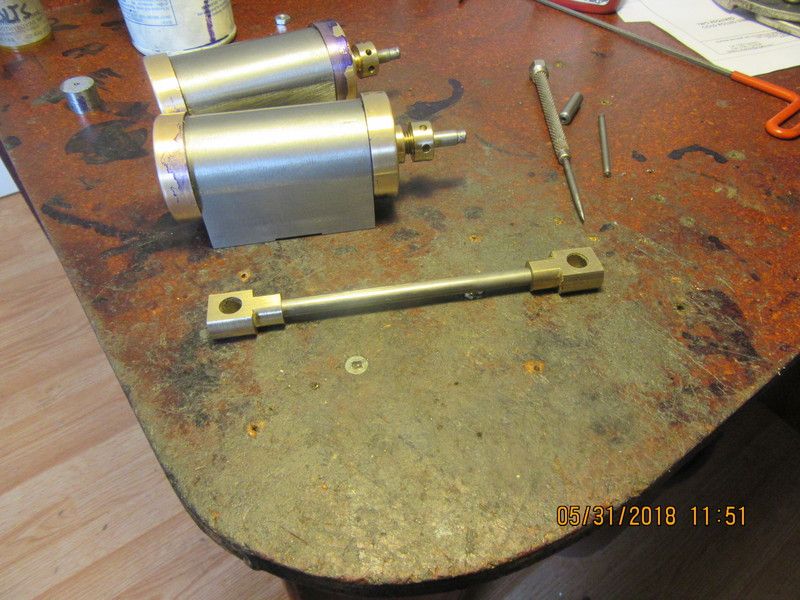
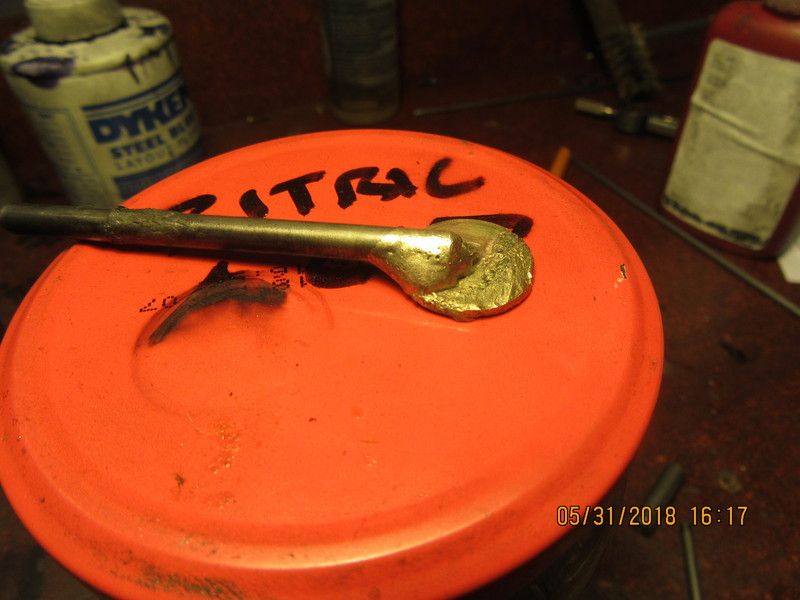
Here we have a shot of the two piston rod ends, still attached to the main piece of round bronze they were machined on. It is set up in the rotary table and the two sides have been machined flat. Then the 5/16" holes were drilled and reamed in the same set-up. The part was moved back into the lathe, where the one closest to the end which had already been drilled and reamed to 1/4" was parted off. Then the remaining one was drilled and reamed to 1/4" and then it was parted off. A little rub on my 150 grit emery paper laid out flat on my cast iron band-saw table, and Presto!! We have two more finished parts. I can't remember--I think I can silver solder the bronze ends onto my cold rolled 1/4" piston rods. I may have to do a little test first on a scrap of bronze. I don't want to screw these up. If I have to I can cross-drill and pin them to my piston rods.


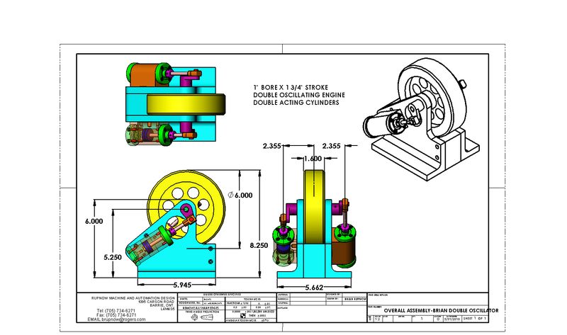
I just realized that I haven't given any real information about the size of this engine. It doesn't occupy a lot of space, and most of it is cylinders and flywheel.

I did a little test, and yes, it appears that you can indeed silver solder bronze to steel. The solder bonded well to the bronze, but it seems that the heat has caused some alloy in the bronze to "boil up" to the surface and leave a bit of a mess. I think I'm going to play it safe and pin the bronze piston rod ends too the piston rod shafts.

velocette
Well-Known Member
- Joined
- Sep 11, 2011
- Messages
- 184
- Reaction score
- 54
Hi Brian
Here Goes I'll stick in my Totally Biased Opinion on good Brazing-Silver Soldering technique.
The bit that I would like to add is that you use the flame and hot gas stream to protect the area of molten metal at all times by NOT flicking the flame sideways on and off the area to be Joined!!!
Move the Torch closer or further away from the joint keeping the flame on the area you are working on this will allow you to control the temprature of the molten puddle from liquid to solid.
The Enemy of molten Silver Solder is AIR.
Whatever source of heating is used it is the hot and almost inert gas that is the flame and hot gas stream that will protect the puddle.
Eric
No, that wasn't a penny. It was a 1/16" offcut from a 5/8" bronze round bar.
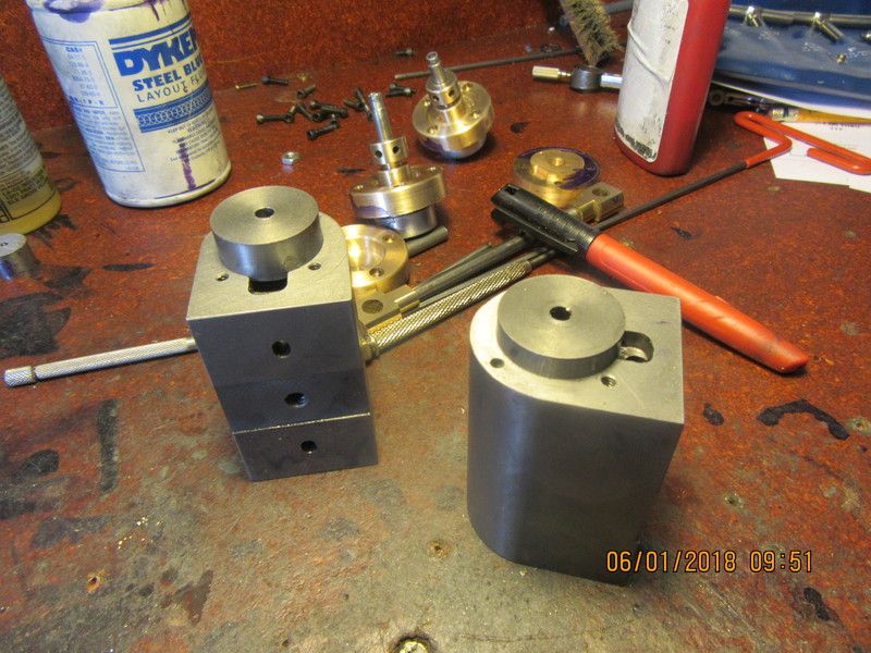
This mornings work was to make two cast iron pistons. I had enough short ends of cast iron left over from making cylinders that I was able to find a couple that were "just long enough". I turned both pistons down to about .0005" oversize, then "wrung" them into the cylinders using 600 grit compound. One piston fits really good, one is a little looser than I like, but when I put in a couple of v shaped oil grooves on each piston, that will displace enough material either side of the V to make them fit perfectly, in fact they might have to be "Wrung in" again to get them into the cylinders.

Similar threads
- Replies
- 4
- Views
- 810
- Replies
- 413
- Views
- 56K
- Replies
- 148
- Views
- 25K


