You are using an out of date browser. It may not display this or other websites correctly.
You should upgrade or use an alternative browser.
You should upgrade or use an alternative browser.
Building Jerry's Donkey
- Thread starter Captain Jerry
- Start date

Help Support Home Model Engine Machinist Forum:
This site may earn a commission from merchant affiliate
links, including eBay, Amazon, and others.
- Joined
- Jun 4, 2008
- Messages
- 3,294
- Reaction score
- 636
From that picture, I can only conclude, "You are Iron Man"
- Joined
- Dec 2, 2008
- Messages
- 971
- Reaction score
- 9
No, I'm not "Iron Man". Here is a picture of me and "Iron Man" together. That's "Iron Man" on the right.


- Joined
- Dec 2, 2008
- Messages
- 971
- Reaction score
- 9
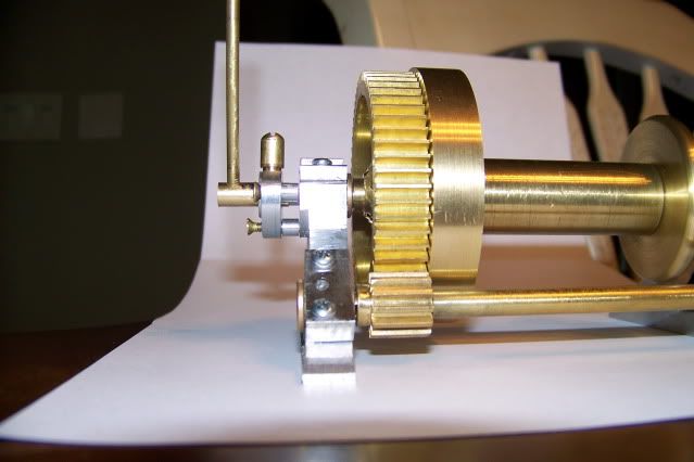
Well, into the shop to deal with the clutch lever. I had a general idea how I was going to work this out, but things changed a bit as I got into it. Several months ago, I posted some drawings that looked good but as I got into it things changed. I planned to use a pin that was in a hole crossdrilled in the actuator shaft. It woud engage slots cut diagonally in a bushing that simulated internal threads. I had a hazy idea how I was going to get the pin in the shaft and the shaft in the bushing and the bushing in the frame, but it got way to complicated to be built.
The final version uses a solid shaft with one 1/16" slot milled across it at 70 degrees. The single pin that provides the axial thrust is disguised as a grease cup on top of the frame in the pictures below. This pin engages the slot and when the shaft is rotated with the handle through an arc of about 55 degrees, the shaft is moved about 3/32" pressing on a pin that moves in the shaft bore, pushing on the clutch bushing and engaging the clutch. Sounds to simple but it works a treat. This is the right hand thread on the main hoist. The left hand thread needed for the front hoist just means that the slot will be milled at the opposite angle. Problem solved.
I didn't take pictures. For one thing inspiration and execution was happening so fast, I could barely keep up. For another thing, the wife was babysitting both of the great grand daughters, so she got dibs on the camera. I brought the results home and took some pictures of the assembly. It may not be ready for prime time but this is a work in progress. My philosophy is make it work, then make it pretty. I know, the fasteners are crappy and the finish is rough and the grease cup is way out of scale, but its progress. Have a look.
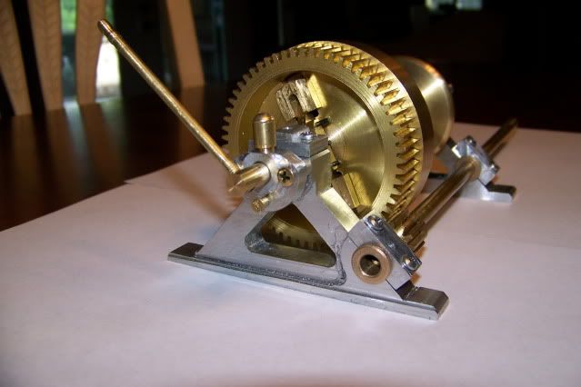
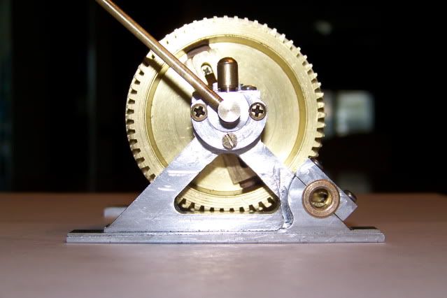
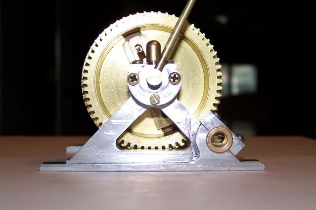
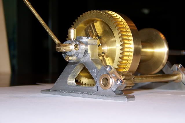
If that,s not enough pictures, tell me, I got more.
Jerry
The final version uses a solid shaft with one 1/16" slot milled across it at 70 degrees. The single pin that provides the axial thrust is disguised as a grease cup on top of the frame in the pictures below. This pin engages the slot and when the shaft is rotated with the handle through an arc of about 55 degrees, the shaft is moved about 3/32" pressing on a pin that moves in the shaft bore, pushing on the clutch bushing and engaging the clutch. Sounds to simple but it works a treat. This is the right hand thread on the main hoist. The left hand thread needed for the front hoist just means that the slot will be milled at the opposite angle. Problem solved.
I didn't take pictures. For one thing inspiration and execution was happening so fast, I could barely keep up. For another thing, the wife was babysitting both of the great grand daughters, so she got dibs on the camera. I brought the results home and took some pictures of the assembly. It may not be ready for prime time but this is a work in progress. My philosophy is make it work, then make it pretty. I know, the fasteners are crappy and the finish is rough and the grease cup is way out of scale, but its progress. Have a look.


If that,s not enough pictures, tell me, I got more.
Jerry

$39.58
$49.99
Becker CAD 12 3D - professional CAD software for 2D + 3D design and modelling - for 3 PCs - 100% compatible with AutoCAD
momox Shop
![DreamPlan Home Design and Landscaping Software Free for Windows [PC Download]](https://m.media-amazon.com/images/I/51kvZH2dVLL._SL500_.jpg)
$0.00
DreamPlan Home Design and Landscaping Software Free for Windows [PC Download]
Amazon.com Services LLC

$39.99
$49.99
Sunnytech Low Temperature Stirling Engine Motor Steam Heat Education Model Toy Kit For mechanical skills (LT001)
stirlingtechonline

$24.99
$34.99
Bowl Sander Tool Kit w/Dual Bearing Head & Hardwood Handle | 42PC Wood Sander Set | 2" Hook & Loop Sanding Disc Sandpaper Assortment | 1/4" Mandrel Bowl Sander for Woodturning | Wood Lathe Tools
Peachtree Woodworking Supply Inc

$89.99
Outdoor Wood Boiler Water Treatment Rust Inhibitor- AmTech 300 & Test Kit
Alternative Heating & Supplies

$99.99
AHS Outdoor Wood Boiler Yearly Maintenance Kit with Water Treatment - ProTech 300 & Test Kit
Alternative Heating & Supplies

$94.99
$109.99
AHS Woodmaster 4400 Maintenance Kit for Outdoor Wood Boiler Treatment
Alternative Heating & Supplies

$45.99
Sunnytech Mini Hot Air Stirling Engine Motor Model Educational Toy Kits Electricity HA001
stirlingtechonline

$12.56
$39.95
Complete Plans for Building Horse Barns Big and Small(3rd Edition)
ThriftBooks-Atlanta

$519.19
$699.00
FoxAlien Masuter Pro CNC Router Machine, Upgraded 3-Axis Engraving All-Metal Milling Machine for Wood Acrylic MDF Nylon Carving Cutting
FoxAlien Official
- Joined
- Dec 2, 2008
- Messages
- 971
- Reaction score
- 9
Jared said:I love it! Are you going to post plans when you're finished?
Jared,
I didn't overlook your question about posting plans, I just forgot to answer. The truth is I don't know. I am not a trained draftsman and although I can produce a 3d model with full motion, and produce a working drawing with the dimensions I need, the part often doesn't get built that way and I don't always go back and modify the model and the drawing. The drawings and dimensions make perfect sense to me but a real machinist might be so irritated by them that someone might get hurt by flying tools.
Still, if someone wanted to build one of these or for that matter if anyone wanted to build any of my other original design (Weeble, or 3 Cylinder Spider) I would be willing to help, including drawing with the above caveat. But lets see if I can get this thing completed first.
Jerry
- Joined
- Dec 2, 2008
- Messages
- 971
- Reaction score
- 9
Back to the shop. Vacation is over, including a week in the north Georgia mountains complete with an unexpected bear encounter. I should be feeling restored and raring to go but the heat is so intense that it overpowers my shop AC by noon so I'm going to work short hours until it cools off some.
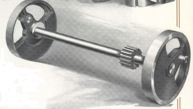
Here is a shot of the crankshaft from the American Hoist Brochure. Note the eccentrics integral with the crank webs.
Here is my version.
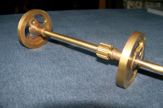
This looks like a straightforward assembly but there are hidden pitfalls. The original shaft has the webs Shrunk to the shaft with a square key. The gear also fits over a square key but it is not obvious how it is secured. I'm not setup to cut internal key ways and there is not room to use a grub screw so I decided to solder the web disks to the shaft.
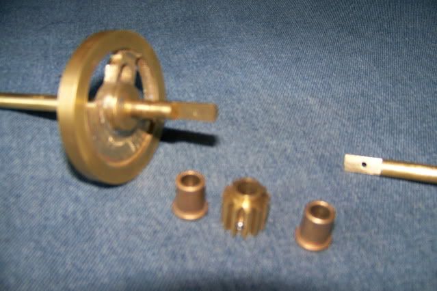
That presents more problems. How do I fit the gear and the oillite bushings. I could fit the pieces to the shaft before soldering the webs but I know I will regret that in the future if either needs to be replaced. The solution that I came up with is a two piece shaft. The shaft is milled to 1/2 thickness for a length of 1/2". I was going to join them inside a collar but there is the gear which will serve the purpose. What may not be obvious is that the two halves of the shaft are not clamped together. They are jacked apart inside the gear. The grub screw passes through a clearance hole in the gear, threads into one half of the shaft and presses against the other half, forcing the two halves apart, griping the gear and making a surprisingly rigid assembly.
Thanks for watching
Jerry
Here is a shot of the crankshaft from the American Hoist Brochure. Note the eccentrics integral with the crank webs.

Here is my version.

This looks like a straightforward assembly but there are hidden pitfalls. The original shaft has the webs Shrunk to the shaft with a square key. The gear also fits over a square key but it is not obvious how it is secured. I'm not setup to cut internal key ways and there is not room to use a grub screw so I decided to solder the web disks to the shaft.
That presents more problems. How do I fit the gear and the oillite bushings. I could fit the pieces to the shaft before soldering the webs but I know I will regret that in the future if either needs to be replaced. The solution that I came up with is a two piece shaft. The shaft is milled to 1/2 thickness for a length of 1/2". I was going to join them inside a collar but there is the gear which will serve the purpose. What may not be obvious is that the two halves of the shaft are not clamped together. They are jacked apart inside the gear. The grub screw passes through a clearance hole in the gear, threads into one half of the shaft and presses against the other half, forcing the two halves apart, griping the gear and making a surprisingly rigid assembly.

Thanks for watching
Jerry
A great solution Jerry, two birds with one stone or should that be grub screw.
Bogs
Bogs
- Joined
- Dec 2, 2008
- Messages
- 971
- Reaction score
- 9
Bogstandard said:A great solution Jerry, two birds with one stone or should that be grub screw.
Bogs
Grub screw conservation is everyone's responsibility. I'm just doing my best to be responsible.
Jerry
- Joined
- Jun 4, 2008
- Messages
- 3,294
- Reaction score
- 636
If you had taken your pic in B&W, you could have made ppl guess which was which. :bow:
- Joined
- Dec 2, 2008
- Messages
- 971
- Reaction score
- 9
Thanks to all who are following this build and special thanks to Dean, Bob, Kvom, Bogs, Sam and Philly for taking the time to respond. What I enjoy most about this hobby is the small AHA! moments when a surprising solution jumps out at you. It is also great to be able to show it to an appreciative group of model engineers around the world.
There are lots of challenges remaining. In spite of the fact that I have built several engines in the past, I have never built a conventional double acting cylinder with a D-valve. I have no plans so I have to work out all the details and dimensions myself. Not really difficult if you know how but I don't. The interactive Zuener diagram written by Charles Dockstader has been getting a real workout and I think I've got a pretty good set of dimensions worked out.
The cylinder has a .625" bore and a 1" stroke in keeping to 1/10th scale.
The eccentrics have a center offset of .0935" which gives a valve travel of .1875"
The steam valve slots and the exhaust ports slots will be 3/32 (.0934)" wide wit a 3/32" flat between them.
The valve cavity will be .282" wide and the valve plate will be .470" wide.
These dimensions produce no lead, no lap, 100% cutoff. There is no expansion and no compression.
The engine will run on compressed air.
Would performance be improved by tweaking any of these specs?
Thanks in advance for your suggestions.
Jerry
Edited to correct loose decimal position and to correct eccentric throw. (JLG)
Similar threads
- Replies
- 6
- Views
- 528
- Replies
- 11
- Views
- 1K


