Building Jerry's Donkey

Home Model Engine Machinist Forum

Help Support Home Model Engine Machinist Forum:

This site may earn a commission from merchant affiliate links, including eBay, Amazon, and others.

I just had to say 'WOW!'. That is awesome looking.

Sorry I can't help with the problem.
 
Thanks for all the good suggestions, ranging from the very simple to more than I want to think about. I like simple and following Hippocratic principles (first, do no harm), this is my plan,

I'll complete the assembly with proper links and fitted pins. I might get lucky and have it all work without adjustment.

don-tucker said:
Here's my fourpenneth,once the shoes are applied a few times I feel that they will wear in that few thou,knowing you will have got them as near as damn it.
Don

If its not quite right, it may wear in and seat itself after it has loaded a few tons of logs but I'm not very hopeful. The brass face is as slick as snot and the oak is very hard. My fear is that even if it fits very well, it may not provide a good enough "grip" without a lot of pressure.

Maryak said:
Jerry,

Is it possible to:-

1. Shim the laggard link.

2. Reduce the length of the slot in the laggard clutch timber.

I realise we are talking small numbers here but.................. just a couple of thoughts to complement bogs suggestion.

Best Regards
Bob

I don't know how I would keep a shim in place but going the other way, I could file a bit off the outer end of the brass slider on the proud timber. A few licks might be enough.

Bogstandard said:
Jerry,

The amount of differential movement required is going to be very small.

Could you open out the centre of the main operating bush by say 0.010", and it's locking pin hole in the main shaft by about the same amount, but still retain the pin size in the main bush, so that the operating bush is actually 'floating' around the shaft, but still getting drive thru the pin.

That way, if one of the shoes comes into contact first, the 'float' would still have enough movement to allow the second shoe to come into contact as well. A sort of self centring effect.

I doubt if that little float would be noticeable on an engine of this size.

I hope you understand the method, and it is only a suggestion.

Bogs

This might be a good fix even if everything fits right on the first try or after filing to fit. I takes care of atmospheric changes in the oak. It is self adjusting within limits. As it is now, the bore in the sliding bush is reamed to a close siding fit but there is no reason that it needs to be that close. Opening it up a bit lets the bush, the links, the plates, and the shoes work as a unit conforming to the fit in the drum, not the shaft.

It also eliminates the possibility of the bush binding on the shaft over time with wear material from the shoes. That's one of the reasons that I decided to go with oilite bushings throughout. I don't want excess oil contaminating the oak shoes or forming a gunk with wood dust.

steamer said:
To echo Bob and Don's posts, can the assembly be locked in place and machined concentric to the shaft?.....( On the lathe or on a rotary table on the mill...ect)

Once close, it will wear in fairly quickly I think.

PS.... in looking at the illustrations posted earlier, I think you could machine these.

I would make up a sacraficial face plate ( held in a 3 jaw or what have you but faced and bored in situ just prior to use)
Mount the assembly on the shaft but minus the clutch drum. If you make a clamping washer that fits with clearance over the central hub, but clamps the shoes to the faceplate in their natural location ( positioned radially by their own links), then take a slight turning cut on the shoes to make them concentric. The clamping washer could be held via a custom bolt with a body diameter the same size as your clutch shaft.

Here is the COC.....hope it helps!

Dave

I hope it doesn't come to this. It might work but in my shop, there is lots that could go wrong here and great harm could be done!

zeeprogrammer said:
I just had to say 'WOW!'. That is awesome looking.

Sorry I can't help with the problem.

"WOW" indeed. This is really fun. I keeps getting funner!

Thanks for all the help. I think I am back on track. There will be a video of the donkey running next week! Or maybe the week after!

Jerry
 
Fair enough Jerry.

I was at my kids baseball practice this morning and it occured to me.

Just file it.!

Figure out which one is longer, and take a stroke or two off with a fine file....it will remove stock very slowly and can't get away from you.....if you over do one, file the other one.....Once your close, it will wear in to perfection in use....

The solution doesn't always have to be high tech...I need to remember that... ;D

Dave
 
Jerry---this is a fascinating build, and you are doing a marvelous job. I have never cut a gear, and I would like to try to do so, in fact I will probably try to make the same 60 tooth gear that you made. In the very first page of this thread, you talk about "Dressing a mounted point to a specific diameter" to grind the radius on the single point cutter. I don't really understand what you meant. Firstly, I'm not sure what a "mounted point" is, and secondly---are you talking about somehow turning a grinding stone to the specific diameter required to grind the radius.----Brian
 
That sure looks neat, Jerry. It's going to be a beautiful thing!

I think Bogs has the solution, if you think about a similar mechanical movement that many of us are
familiar with. Brake shoes in a typical automotive drum brake look completely different in the way
they are actuated, but really, it's similar to what Bogs lays out. In a car, one brake shoe always starts
the job first, then transfers a small motion through a pivot to get the other one taking up the slack.
Even though the pivot point for that action is not at the centerline of the two shoes, like on your clutch,
it's still doing what John describes. It equalizes things the same way letting your central bush float
would do for your clutch. It sounds good and proper to me.

Watching for your next post!

Dean
 
Dave and Dean

I agree that a combination of small steps is the best approach. I was a bit reluctant to proceed until I had a good plan. I didn't want to start down a wrong track if there was a better direction. I think I'm headed the right way now and small adjustments should make it work out in the end. Bogs' fix takes a lot of the worry out of it. It will be a case where a loose fit solves a problem rather than causing one.

As far as comparing it to modern drum brakes there is one characteristic of drum brakes that I want to avoid. In either direction, one shoe of a drum brake set is slightly self actuating. Friction with the drum tends to rotate the shoe outward, applying more pressure, more friction, more pressure .......... A really good thing before power assisted brakes. (I'm a really old guy) It's not such a good idea on a hand applied clutch.

Here's why. My first thought was that the operator used the clutch control to hoist a load and used the foot applied external band brakes to control lowering the load. That may not be so. External wrapped brake bands are much more "self actuating" and notoriously "grabby". A careful reading of the AMHOIST brochure seems to indicate that the smooth action of the clutches was used for precise control of lowering.

In any case, I headed for the shop this morning planning to get on with it. By the time I got all the wood chips vacuumed up, the temp in the shop was approaching 90 deg F. and the AC was losing ground. I got the bright idea of cooling down the aluminum roof with a water hose spray to geve me a chance of getting something done. There is a hose bib attached to the shed and as soon as I opened the valve, I heard the pump start and immediately stop. The pump is about 100 yards from the shed so I grabbed a some tools and headed that way. Sometimes the relay gets stuck and a few knocks will get it going. Not so. The relay housing was packed solid with spider webs and the points had arced and needed filing. As soon as I got that done and got the pump going, one of the float controlled automatic valves on one of the horse watering stations nearby started spraying water everywhere. Failure of a PVC pipe joint was the problem. By the time I got that fixed, I was so hot, wet, dirty, sweaty and pissed off that I decided it was not a good time to work in the shop so I sat on the porch with a beer and the dog and took a nap. Tomorrow may be cooler.

Brian Rupnow said:
Jerry---this is a fascinating build, and you are doing a marvelous job. I have never cut a gear, and I would like to try to do so, in fact I will probably try to make the same 60 tooth gear that you made. In the very first page of this thread, you talk about "Dressing a mounted point to a specific diameter" to grind the radius on the single point cutter. I don't really understand what you meant. Firstly, I'm not sure what a "mounted point" is, and secondly---are you talking about somehow turning a grinding stone to the specific diameter required to grind the radius.----Brian

Brian,

If you're still with me, do it!, You'll like it!

What I call a "mounted point" is a stone permanently fixed to its own shaft, not on a mandrel usually used in a die grinder or a Dremel. Cheap hardware store items less than $2 apiece in various diameters. I use them at much slower speeds in the drill press so that using the little vise and the adjustable table angle, I can get the relief angles right.

The problem, as I saw it after downloading the CAD file from Rush, would be to grind a precise radius on the face of the cutter with only a few degrees of arc to measure. The answer was to pick a stone slightly larger in diameter and dress it down to the correct diameter. A diamond pointed wheel dresser would be nice but I don't have one. I do have a $5 set of "miniature diamond abrasive discs" that do the job just fine. Hand held and pressed against the stone, they bring it down to the needed radius in a hurry. Its easy to measure the stone and then you don't have to measure the radius on the face of the cutter. Just get a full contact arc and you've got it. The relatively slow surface speed of the small stone means heat build up is minimal and you can maintain and control contact for 5 or 10 seconds at a time without burning the steel or your fingers.

You'll work it out. It's pretty easy. I've been following all the threads on making hobs and IMHO this is way easier. I hope this helps. I'm certainly not an expert but I think I've worked out a fairly simple and repeatable method. Let me know if its still not clear.

Jerry
 
Brian Rupnow said:
Thanks Jerry---I think I understand now. Perhaps I will start a thread on it.---Brian
Brian

Go ahead with a new thread if you want to, but search the forum for previous threads first. There is a lot of good information. I am a total novice at this, having made four gears so far, and my only source of information was the previous threads and discussions by the more experienced members here on HMEM. I only included the narrative on my experience because it is central to the Donkey project. I'll be glad to join in on your thread if it will help.

Jerry
 
Jerry--I would be very glad to have you join my thread. I am a complete NOVICE at gear making, so the thread is not intended to tell others how to make gears. It is more intended to show how I would approach it from my perspective as a novice. Any possible help would be greatly appreciated. ----Brian
 
The donkey clutch design underwent some changes today. This is how it happened. There was insufficient force applied to the clutch shoes to get a good grip on the clutch drum. Effort is applied through the shaft and is translated to outward effort through the links. The mechanical advantage of this type of linkage varies as the sine of the angle that the link makes with shaft. If the links are parallel to the shaft, no outward force is created. As the angle increases the force increases. At a 45 degree angle, the mechanical advantage is 1:1 and as the angle approaches 90 degrees, the mechanical advantage increases dramatically.

The engineer in the office knows this and thinks he's got it covered but when it comes to assembly its not working out as well as he had planned. The machinist takes one look at it and says "that angles too steep. Needs to be flatter." The engineer says "You're right. I'll go back and make some changes."

The machinist says "While you're at it, you need to reduce the depth of that hub. It's gonna innerfere with the links if you don't" The engineer says "Right again, but is going to take me some time to make all the changes. I'll get revised drawings back to you in a few days"

The machinist says, "Don't bother, I'll just make it work the way it ought to. You can change the drawing to match later."

The engineer says, "Go ahead, do whatever you think is best"

Its working much better now but the engineer still hasn't got the drawings revised.

Jerry
 
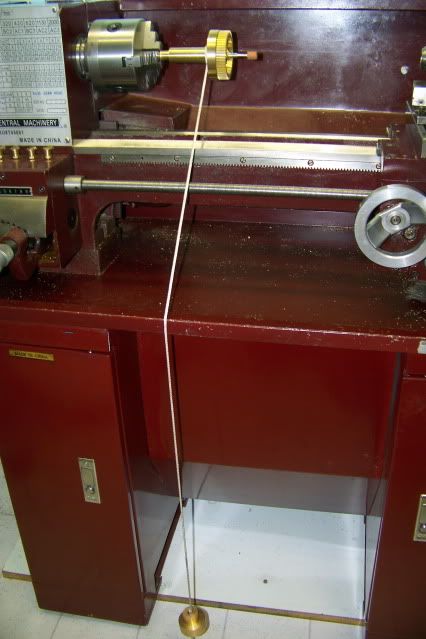
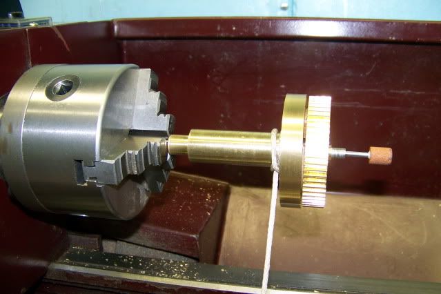
When I left the shop today, I had to make a side trip to the grocery store. I had a hard time driving, I was so busy patting myself on the back. The clutch works beyond my wildest expectations. With a few changes to the geometry that I will show later, I had what looked like a working hoist clutch. It looked good but needed testing. Here is the test setup.

Jerrysdonkeyclutch005.jpg


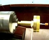
Jerrysdonkeyclutch006.jpg


The shaft is driven by the lathe.

The gear turns with the shaft.

The drum freewheels on the shaft.

The little rod sticking out of the end of the shaft does not turn at all.

If I press on the little rod, the shoes expand and grab the drum, making it rotate and lifting the weight.

If I let off the pressure, the clutch disengages and the drum freewheels. and the weight falls.

If I feather the clutch, I should be able to hold the weight or lower it under control.

I can't hold the camera, control the clutch, and describe what's happening at the same time so just watch this video:


The amount of pressure required is VERY little. The distance move is imperceptible. Its almost ZEN like. Think "up" and it goes up. Think "down" and it goes down. Think "hold" and you can stop the weight anywhere!

I can hardly believe it!

Jerry
 
That - is - super, Jerry! It works perfect.

Thanks for the vid. It's fun watching it work!

Dean
 
Jerry,
Sweet!
Dennis
 
Jerry,

I'm sure it works a treat and congratulations. :bow:

I have one small problem PB says it can't find the video. :mad: I will try again in the morning when the wireless link is not so busy and I have a bit more bandwidth.

Best Regards
Bob
 
Great job Jerry! I am glad it all worked out for you. :)

Dave
 
Jerry

This is coming along really well. I've long been interested in building a donkey engine, watching your version has re-enforced the desire!

Cheers, Joe
 
Jerry,

Oh that's great piece of work but, seeing a smile at the end of the video would have been priceless ;D

Regards

Philly
 
Dean, Dennis, Bogs, Bob,
And Dave, Zee, and Philly,

Thanks for watching and taking the time to comment. These little victories are so much sweeter when they are shared. Not many people here in horse country understand the challenges much less the victories.

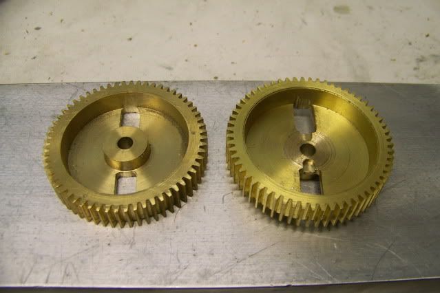
Here are some of the changes made in the shop that helped get it working. The angle of the links between the floating bush and the sliding shoes needed to be flatter but the hub in the gear face prevented that. The original is on the left, the revised is on the right. Hub removed.

Jerrysdonkeyclutch001.jpg


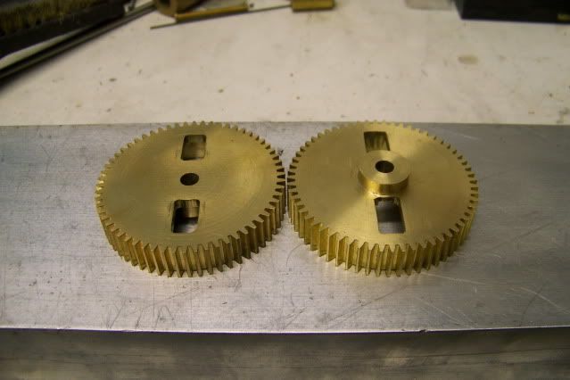
The gear still needs a hub to be stable on the shaft and to provide a mean of securing it to the shaft, so it was moved to the other side as seen here:

Jerrysdonkeyclutch002.jpg


The clutch disk had to be modified to provide clearance for this.

With the links at a lower angle, the sliders would not stay in contact with the shoes so I had to revise my position on fasteners. I did not like the idea of a screw inside the clutch working loose and scoring the drum face so I had to run the screw through a clearance hole deep inside the slider and into a tapped hole in the oak shoe. I used a #2-56 machine screw and let it self-tap into a 5/32" hole in the oak which is hard enough to take the thread without stripping.

As to the post from yesterday about the conversation between the engineer (me) and the machinist (me) is that 3D modeling has its limitations. Even if you animate the model and move the pieces, the pieces only move in the manner that you define. In the shop and the real world, they move wherever they damn well please. The real world is full of surprises.

Now that I have this issue licked, I can move on to one of the really ticklish bits that I new early on in this project would be touchy. Translating the 45 degree rotation of the clutch control handle into the linear thrust of the push rod on the clutch. Until now I was not sure what the distance was that the rod would have to move to drive the clutch. I now see that it is almost nothing. I think I can make this work!

Jaw set, clenched fist, and steely eyed, I'm off to the shop to do battle.

Jerry

PS Here's a picture of me smiling, beaming actually

Jerrysdonkeyclutch009.jpg


Latest posts

Back
Top