Thanks Dean ;D - I forgot about chewing on pencil ends :big: - Last time I did that was in 1990 in draughting class in school - no CAD back then and a selection of pencils of different hardness for drawing different line types. This was just about the only class in school for which I did homework - I loved drawing the parts! Didn't like the paint that came off then ends though!
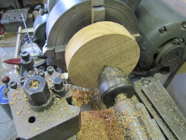
Today I started off with a bit of brown stuff. I'm not particularly fond of woodwork, but can do a "sort of OK" job of it when needed. Just used a jigsaw to hack a squarish bit off the piece of wood I bought earlier this week, drew a circle on it and trimmed off most of the excess outside of the circle with the jigsaw, and stuck it up on the lathe by pressing the revolving tail center into the center of the circle and squeezing it down on the face of the 4-jaw chuck pretty hard. Then with a very sharp HSS toolbit, just turned it down:
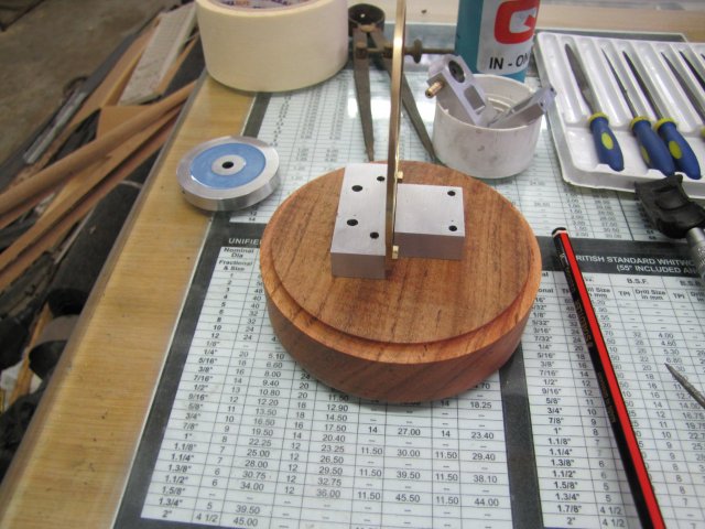
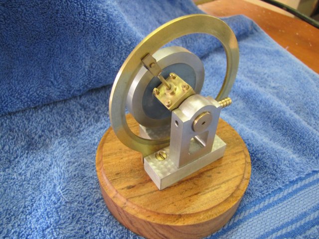
After some more turning, and then a bit of sanding followed by some floor/furniture wax, the wood base was good to go, so I marked the mounting hole locations using the engine base itself as a jig:
After drilling pilot holes for some brass wood screws, I sanded the wood base down again, and then coated it thickly with more of the wax and set it in the sun so the wax could melt a bit and seep into the wood.
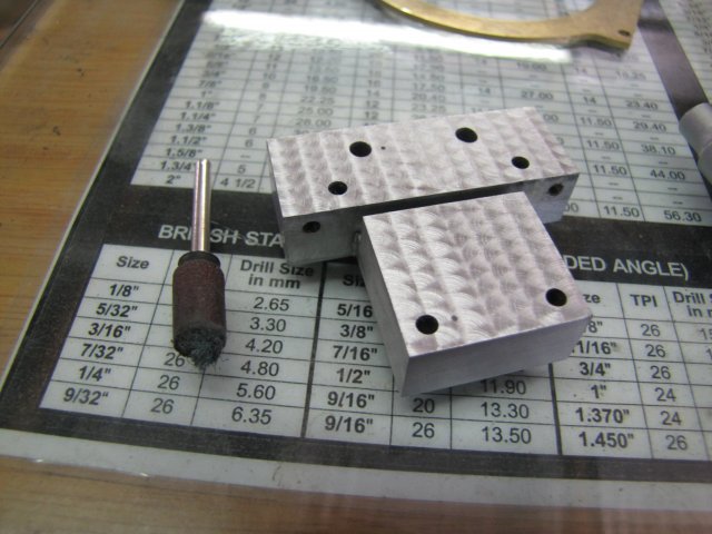
Earlier on this week I did some experimentation on the "stuffed" base I made right at the start. I've never done engine turning, and was toying with the idea of doing some on the base. I tried a couple of different methods; from wood dowels coated with grinding paste to sticking some emery on the tip of some 6mm rod; nothing worked particularly well though. I finally hit on cutting a bit of Scotch-Brite off a pad, and using a small drum sander from my Dremel's kit with a worn-out sanding drum as retainer - with a "pocket" left on the bottom to shove the bit of Scotch-Brite in. This worked OK, so while the wood base was languishing in the sun, I did the engine turning on the drill press. The cross-vice was a boon here, as it was easy to get each "touch" in a symmetric pattern. So this is what it came out like; not perfect, but I'm happy with it for now:
After that followed a bit of clean-up of all the parts and a finicky assembly. It's easier to first mount the cylinder in the cam, then slip on the thick bearing/valve block, and then drop the lot on the base and first bolt down the cam and then the bearing block. I'd already soldered the one fork to the connecting rod as per Elmer's instructions at this point. Then slip on the flywheel, and the last bearing block and screw & bolt those down. As a final operation, shift the last fork out and solder that to the con rod. I turned the engine, and had quite a bit of binding...
I traced some binding down to a "tight" spot on the cam; I just used a small half-round file to file down those bits, followed by some 320 grit emery. Thes left a tight spot when the connecting rod was nearly vertical - caused by a tiny excess bit of solder on the forks, so I patiently filed that down as well with some needle files.
Then I gave everything a liberal dose of oil all over the running surfaces, and put it on the compressor for a bit of a run-in. Initially the engine was very stiff and required up to 40psi to start and keep on running. After about 20 minutes with a couple of stops for more oil, it got down to running at about 15 psi. Then I stripped the lot, cleaned all the dirty run-in oil off, and re-assembled with clean oil.
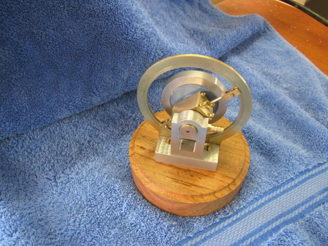
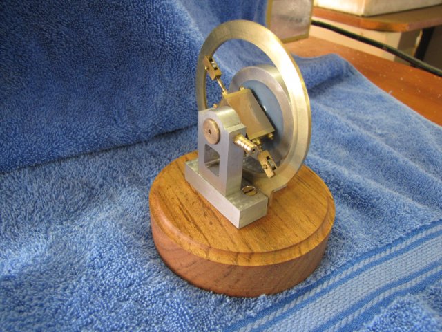
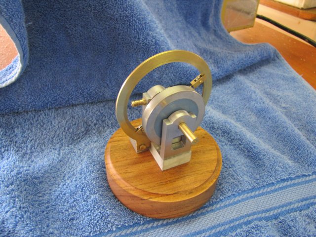
The result:
And the video - :

poorly made once again... :
[ame]http://www.youtube.com/watch?v=NBxAIfydmIQ[/ame]
This was a challenging, but fun, little engine to build; I certainly made more goof-ups on it than any of my other builds. That is completely negated by seeing the little bugger run though; it is extremely interesting to watch ;D ;D ;D
Many Many thanks to everyone who has followed along on this build and provided technical and moral input - It's a pleasure and privilege to share with you guys!
Kind regards, Arnold
Time for a *beer* ;D


![MeshMagic 3D Free 3D Modeling Software [Download]](https://m.media-amazon.com/images/I/B1U+p8ewjGS._SL500_.png)


