Building a Bonzer Bonzer

Home Model Engine Machinist Forum

Help Support Home Model Engine Machinist Forum:

This site may earn a commission from merchant affiliate links, including eBay, Amazon, and others.
Hi Phil,

In the words of Crocodile Dundee: "THOSE are pins!"

I used 1/8" pins on one of my crankshafts that I Loctited (green either 638 or 690) and then tried to improve the runout with a hammer (as you do). And that's when it fell apart.

It is Triumph as in motorcycle. I am about to put it on the market and want to get in a few farewell rides.

Jim

P3280019.jpg
 
Jim,
Very nice bike. I always like the Triumph bikes but back when I was riding, didn't have the cash for one, so I rode smaller Hondas. Now I could probably scrape it together, but I wouldn't ride in my area. Way too many distracted drivers (talking on the phone, texting, blindly obeying the instructions of their GPS etc.).

Seems like I'll be in maintenance mode for a while. Today as I was turning the cylinder on my lathe I started getting a lot of chatter. I had turned the major diameter of 60 mm without incident. When I started turning the 38 mm register I got a lot of chatter. I'm using a four jaw chuck with a live center. I took the toolpost and compound apart and cleaned them but that didn't solve the problem.

When I had the register down to its 38 mm diameter, without removing the work from the chuck I put a dial indicator on the register and I'm getting 0.005" runout. I suspect my inexpensive 4 jaw chuck may have issues. No point going forward until this is sorted out.

Cheers,
Phil
 
Hi Phil,

I have been tidying up my Bonzer and have made a few changes.

The window fell out of the fuel tank so I have redesigned the tank and made it much simpler.

And the vapour carby gave erratic performance so I have reverted to John Williams' original one.

I have emailed you the drawings in both metric and imperial (converted metric) dimensions.

With a bit of luck I will have the new fuel tank finished and fitted before you get to that stage.

Jim

Fuel tank Mk2.jpg
 
Its quite an amazing stunt to fit two valves and a sparkplug on these model engine cylinder heads, isn't it!!! The engine I have been posting about for the last 2 months is a 7/8" bore (22mm) and there sure isn't much real estate there.---Brian
 
Last edited:
Thanks Jim. I'm thinking I won't be at the fuel tank 'till the snow flies:rolleyes:

I did get the 4 jaw chuck problem fixed. After 6 years of fairly regular use, my chuck decided to start separating from its backplate! Who'da thunk:eek: I discovered this when I decided I'd better remove the chuck from the backplate to clean any swarf out from under it. That's when I discovered two screws were not tight, and the other two each could take another half turn.

The bad news is my cast iron workpiece is ruined. The good news is I have enough stock leftover to start a new one, which I did. So far, so good.

I'm still undecided how to turn that middle section down but whenever I am in this position I think "fixture".

Thanks everyone for looking in and for your interest.

Cheers,
Phil
 
Its quite an amazing stunt to fit two valves and a sparkplug on these model engine cylinder heads, isn't it!!! The engine I have been posting about for the last 2 months is a 7/8" bore (22mm) and there sure isn't much real estate there.---Brian

You are not wrong there Brian, have you seen Arv (PutPutMan's) Tiny Four Stroke? I have an impressive collection of heads for Gus to collect and use as sinkers next time he is in Oz. Arv's bore is about 3/8".

I still don't have the engine finished.

Jim

View attachment Tiny 9 Head -- rev B.pdf
 
I'm working on the cylinder now. Got the cast iron ready for the drill.


Drill to 1 inch


Bore to 1.181" (30 mm)


I made a 30 mm dowel out of aluminum to test the bore. I made this on the Logan lathe I kept out of the scrap heap


Some folks complain about cutting cast iron but I'll take it over aluminum any day. I hate that stringy stuff you get from 6061.

Next I need to remove quite a bit of material from the center to make room for the water jacket. Finally tap the #8-32 holes in the flanges on both ends. I"ll post a picture of the cylinder when it's completed.

Cheers,
Phil
 
Last edited:
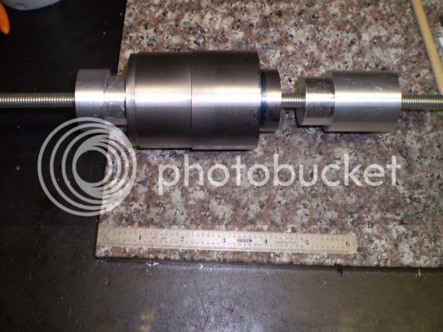
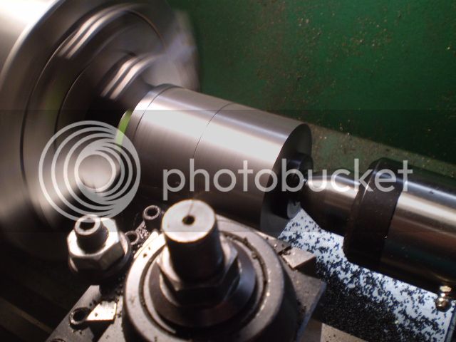
[FONT=&quot]I turned the cylinder around in the chuck and finished the major diameter.[/FONT]

[FONT=&quot]I decided to do all the turning on the lathe at this point and finish with tapping the 8-32 threads on the cylinder ends. The plans call for those threads to be 10 mm deep on 8 mm thick flanges, meaning they’re through holes. I’d rather tap through holes than tap blind holes so I’m going to remove material from behind the threads first, tap the holes second. If this seems confusing some forthcoming pictures should clear this up.[/FONT]

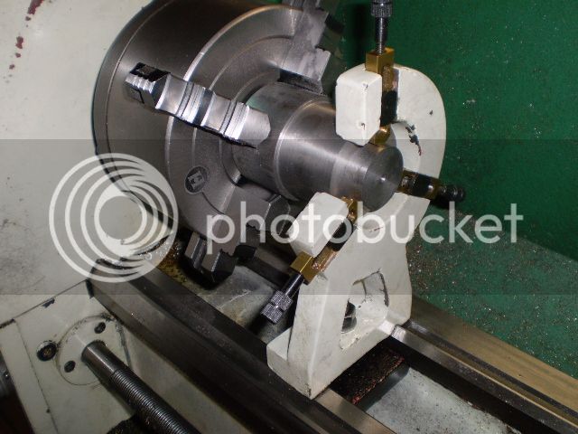
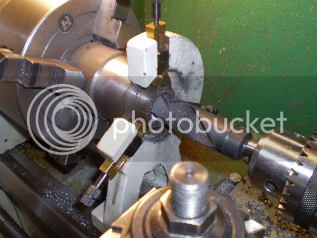
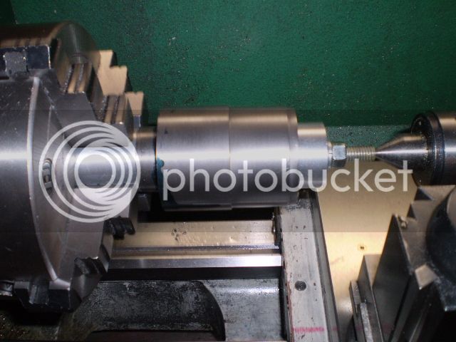
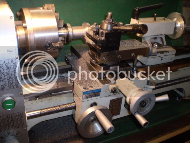
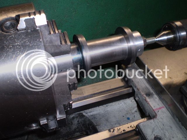
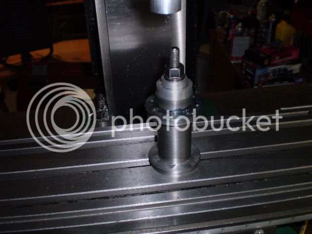
[FONT=&quot]I made an arbor to support the cylinder for turning the end flanges and removing the central portion.[/FONT]


[FONT=&quot] [/FONT]


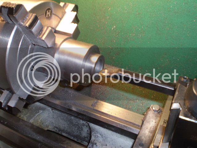
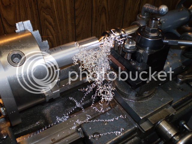
[FONT=&quot]After lots of chips, [/FONT]

[FONT=&quot] [/FONT]

[FONT=&quot]this is the final result[/FONT]

[FONT=&quot] [/FONT]

[FONT=&quot]I made a collar so I could scribe the 47 mm (1.850”) bolt circle to keep me honest. I calculated my x-y moves using trigonometry. [/FONT]

[FONT=&quot] [/FONT]

[FONT=&quot]Holding the cylinder for tapping the threads on one end was easy using one of the arbors I made[/FONT]

[FONT=&quot] [/FONT]

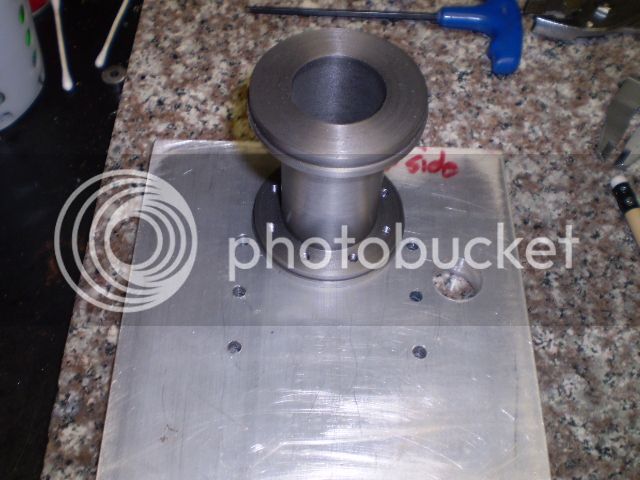
[FONT=&quot]Now I fastened the cylinder to that bogus end plate I made a few weeks ago and tapped threads on the other end. The holes on this end are not symmetrical to allow clearance for the spark plug.[/FONT]


[FONT=&quot]
[/FONT]


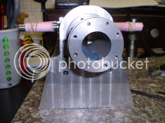
[FONT=&quot]When I finished tapping I examined the threaded holes on the spark plug end. They looked off. The bolt circle is OK but is offset from the bore by 0.020”+. I don’t like this. I double checked all my measurements and can’t find my error. I had indicated off the cylinder bore so I’m puzzled as to the source. That’s troubling because I’ve made a mistake which I can accept, but I don’t know why, therefore, I haven’t learned anything! Here’s what the cylinder looks like mounted on the end plate
[/FONT]


[FONT=&quot] [/FONT]

[FONT=&quot]
[/FONT]

[FONT=&quot]
[/FONT]

[FONT=&quot]It may be hard to see the offset but it’s there. [/FONT]

[FONT=&quot]At this point I think I’ll move on and decide at some point how to make a new cylinder. I remind myself that the definition of insanity is doing something the same over and over and expecting a different result.[/FONT]

[FONT=&quot]As I mentioned at the start of this thread, this will be a long build. I am not in a hurry to get this engine built, just want a good runner.[/FONT]

[FONT=&quot]Cheers,[/FONT]
[FONT=&quot]Phil[/FONT]
 
I think there is something very, umm--Fishy, about using all thread rod as part of your turning set-up. I would guess that your reduced outer diameter is not concentric to the inner bore. Then you moved over to the drill and picked up on outer diameters to zero your quill and start drilling the bolt patterns. I would guess that your bolt patterns are bang on concentric to the outer diameter you picked up on.---Brian
 
Brian,
Sorry if I didn't make this setup clear. The all thread is used to clamp two arbors that have most of their length turned to the bore diameter. You are right about that setup not providing a means of turning dead true outer diameters, though they were fairly good, much better than 0.020".

When I went to drill and thread the second set of holes I picked up off of the bore, not the outer diameter knowing that was not a good reference.

In hindsight, I think I need a better fixture to turn the outer diameters anyway and then maybe I can use it to hold the work for threading the flanges.

Thanks for the food for thought

Phil
 
[FONT=&quot]Well I had a eureka moment last night. After checking my measurements I discovered the source of my error. It was all in the calculations.[/FONT]

[FONT=&quot]The way I’ve always done a bolt circle layout is to use trig. I usually locate on the bore or circle center and move my mill table in the appropriate x and y directions. I’ve never done an asymmetrical bolt layout like there is in Bonzer.[/FONT]

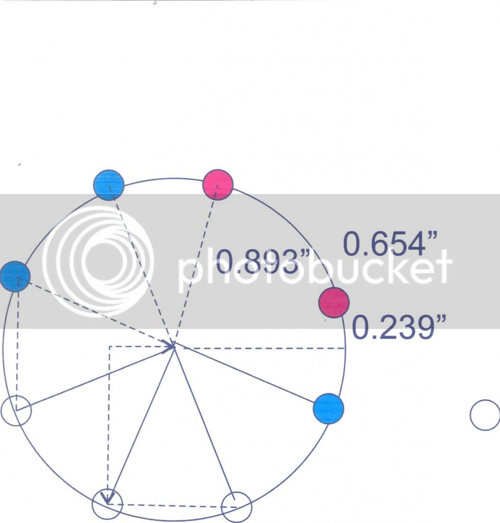
[FONT=&quot]So, in reference to the figure below, the two red circles represent the bolt holes that are asymmetric to the equally spaced remaining six bolt holes (blue and clear). I started tapping the bolts at the red circle at about 2 o’clock. Then I went to the next red circle in a counterclockwise fashion. The problem is that the next bolt hole, the blue circle at 11 o’clock is not on the same y axis as the red circle at 1 o’clock. But I failed to change the y axis setting and that caused the error![/FONT]


[FONT=&quot]It's not too clear by looking at this sketch, but it's there all right.
[/FONT]

[FONT=&quot]I’m feeling a whole lot better having learned something and now it’s time to get back on the horse.[/FONT]

[FONT=&quot]Phil[/FONT]
 
Ah yes, sometimes us Cad guys who are blessed with a good software package forget just how tricky bolt circle trig can be. Twenty years ago, (pre-cad), I could have figured that one out standing on my head. Now I would probably be at a loss too.---Brian
 
Well I've finished the cylinder and am mighty pleased with the results. The bore looks good and there is no evidence of taper to within 0.001". I used a different setup this time with a bull nose live center which I think improved results for turning the flanges.


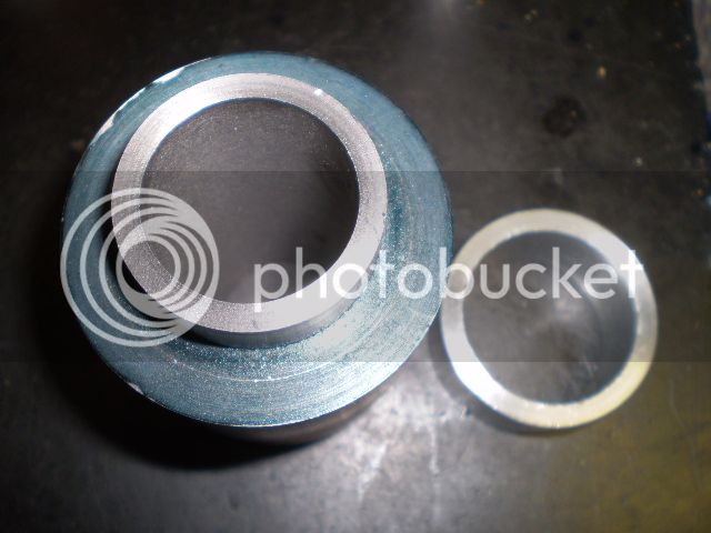
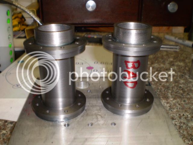
If you look very carefully at my latest product and the previous one shown side-by-side here:


an experienced eye shows which one is not up to standards. (Hint: it's the one marked BAD);)

Time for a break. The con rod or water jacket is next, whichever material I can dig up first.

Thanks for looking in

Cheers,
Phil
 
Hi Phil,

I have made the Mk2 fuel tank for Bonzer and found a problem with the design (clash of two holes) so I have made a couple of changes. I will send you the updated drawings.

Jim
 
Thanks Jim. I've been thinking about the cylinder head and your mod to it so the spark plug comes in from the side. Although you've made the claim that you haven't tried it, I think I'll go that route. Worst case is it won't work, then I'll just go use the original design.

I've started the con rod today and I'm using some 7000 series aluminum for it. I bought some of this stuff on eBay some years ago. It machines very well.

Hopefully, when I'm finished with this build you can take your software and design an engine to use all the bogus parts I've made:D

Cheers,
Phil
 
I will be watching with interest to see how my side plug head works. I think the valve cages are the way to go as well; you can machine the mating surfaces on the cages and the valves at the same setting and they come out needing hardly any lapping.

And I think we all have just about enough dud bits to make another engine when the first one runs. I really should just dispose of the failures instead of keeping them.

Jim
 

Latest posts

Back
Top