Brian's Donkey Engine

Home Model Engine Machinist Forum

Help Support Home Model Engine Machinist Forum:

This site may earn a commission from merchant affiliate links, including eBay, Amazon, and others.
Brian what type of base are you going to mount this on? One of our members mounts all his engines on wood bases which contain a small Filter Regulator and Lubricator (Air Tool Oil) unit. Can I talk you into bringing It down to one of our meetings in Toronto when its finished?
Regards,
Gerald.
 
Steamboatmodel---I don't ususally mount them on any kind of base. The base of that model "as is" is a piece of 7/8" solid aluminum. I can't imagine it requiring any other kind of base. I would love to bring it to Toronto and show it when its finished.---Brian
 
Captain Jerry---Do you have any pictures of one of these control valves?---I don't know if the unit you have access to still has the control on it or not.----Brian
 
tel said:
I dunno Brian, I've made quite a few truncated cones - mainly for reducers in dust extraction lines and I would figure on 2 1/2 - 3 hours top.
Tel---You're a better man than me!!! I'm not saying you couldn't do it in 8 hours, but I KNOW that I couldn't.---Brian
 
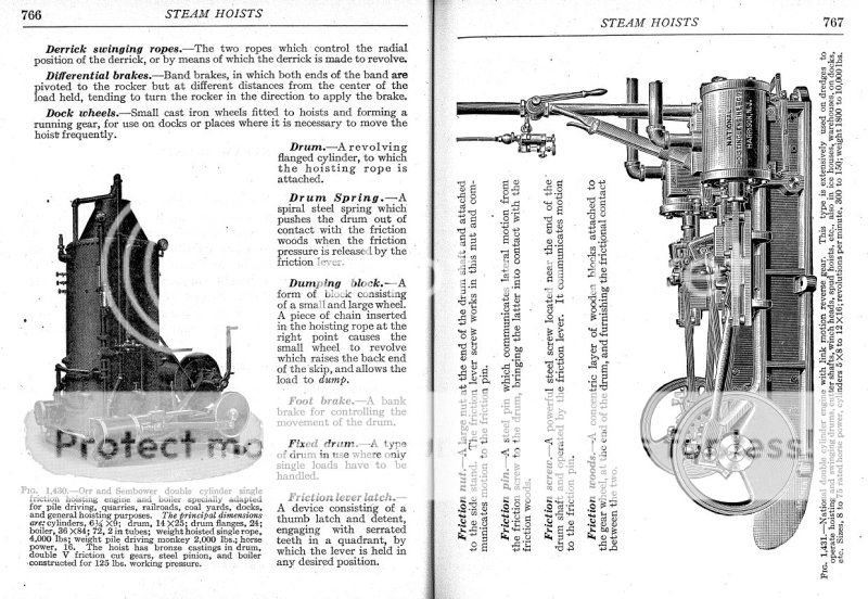
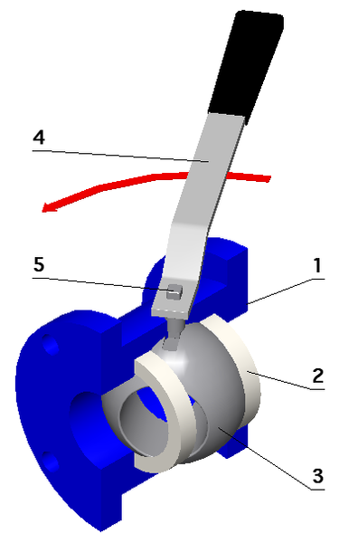
This is a request for help----. I have dug through the literature I have amassed on steam donkey engines, and think I have found the control valve which Captain Jerry was referring to. Its a manual control valve which looks a lot to me like it would be a form of ball valve in the main steam line before it branches off to the two cylinders. Now--It seems to me that I seen somebody post plans on this forum for making a similar simple valve, but I can't remember who nor when. If someone can direct me to that post, I would appreciate it. I would design one myself, but I see problems with it constantly leaking air around the shaft that operates the ball. That shaft can be blind on one side, but it must exit through the housing to mount the handle, so I assume it would require some form of gland.-----Brian
NATIONALDONKEYWITHINLINECONTROLVALVE.jpg

ballvalve.png
 
Brian

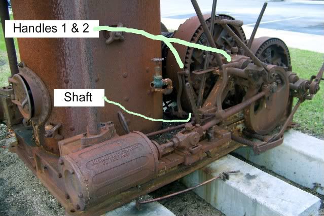
The control valve of the AmHoist Donkey on the docks in Brunswick is long gone. What does remain, although unattached to anything is the control handle. I t took me quite a while to understand what it was because it is just jammed down behind the boiler not attached to anything. There are two handles that look like hand cranks for a Model "T" Ford. They are atached by 50 years of accumulated rust to a common shaft that reaches from the valve at the rear of the boiler to the operators position between the two drums and is supported horizontally by some brackets. The two handles would let the operator control the engine from a position at either drum. I have some pictures that I will look for and post.

In the AmHoist Brochure there is a picture of the actual valve which is very cool. I am considering trying to build one like it for my project. I looks much like a "D" slide valve but much simpler because there is no exhaust but the valve face is flat and a sliding block covers and uncovers the port. When the valve is closed, steam presure holds the slide face against the port face to help seal. There is no description of the gland.

Jerry
 
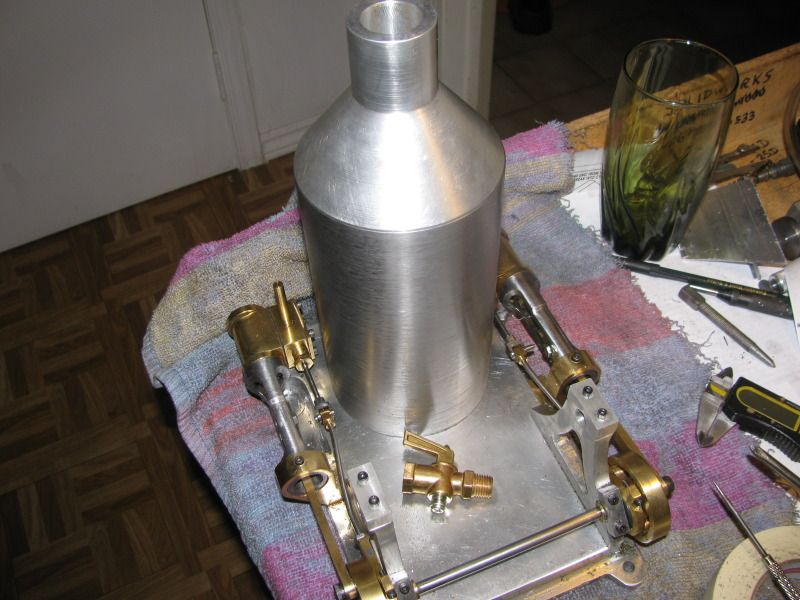
Thanks Jerry. For the sake of visual comparison, that is a 1/4" NPT ball valve laying on the Donkey, and its comparitively huge. Its as big as one of the cylinders!!!
ballvalve001.jpg
 
Hi Brian,
Why does it need to be a 'ball' valve? By that I mean you could make a cylindrical valve just like the ones used one the model airplane carburetors. You make the body of the valve with the shape that you like. You bore blind hole in it. You then fit a cylindrical piece with a stem on it for the handle attachment. This could have .0002 clearance, just enough for it to turn smoothly. This cylindrical piece would have a cross drilled hole in it for the valve action. All you would have to do is make up a cover plate to hold it in place. With a very small clearance you should get virtually no leakage passed the valve and out the stem.
gbritnell
 
Brian

Here is the picture with the two control handles on the shaft. The correct position of the shaft is parallel to the cylinder rod, 4 or 5 feet above it.

SteamDonkey001-1.jpg


Jerry
 
Thanks for the picture Jerry. George---Yes you are right, I've been thinking along the same lines. almost impossible to turn a ball that small to the required accuracy, but a cylinder is fairly easy stuff. Maybe I'll design and build one.---Brian
 
Brian have a look at Ramons table engine thread he has a valve on that. Rather than a ball valve you will find it easier to use a tapered cone much like a cylinder drain cock, they will be self sealing and good for a a couple hundred psi.

http://www.homemodelenginemachinist.com/index.php?topic=16453.msg175170#msg175170

If there is not enough detail on Ramons thread then let me know and I'll give you drawins of either of these two which can be adapted
http://img.photobucket.com/albums/v156/jasonballamy/Engineering/PICT0343.jpg
http://img.photobucket.com/albums/v156/jasonballamy/Fowler A7/PICT0147.jpg

The Valve that Jerry describes is commonly used on traction engines to regulate steam from boiler to valve chest. Its just a loose puck like a slide valve that is held to teh face by steam/air pressure and as it slides back the port is opened

J
 
Stew I don't think a screw down type will work, you need a quick 90 deg on/off action that works with a lever much like cylinder drain cocks
 
Hey Brian,

If its only to throttle with, use a butterfly valve. they are very effective for throttling and are very low force for actuation.

They are also something that can be machined on a lathe in the home shop.

Dave
 
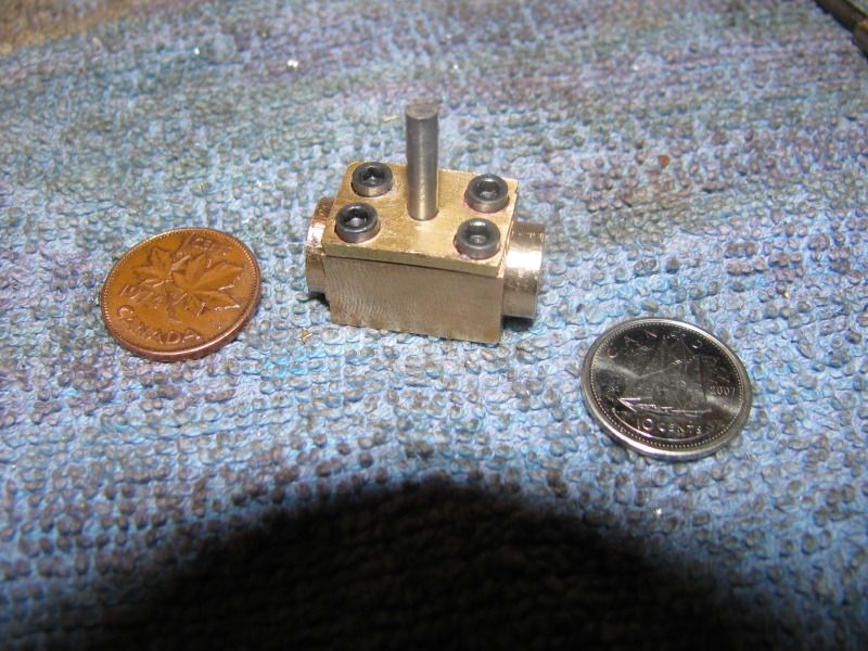
Okay Jerry----Now I can answer your question. This is the valve that will hopefully control the speed of the Donkey engines
Airtight as a ducks butt!!! The o-ring may have been a bit of overkill, but it certainly doesn't leak around the valve stem. Doesn't SEEM to leak through the valve either, near as I can tell. I'm going to revise and repost the main body, as I only made the counterbore that the o-ring sets in 0.040" deep. As a consequence, when you squash a 0.62" cross section o-ring into a 0.040 space, it squabs out too much and makes the valve stem stiff to turn. By the way, that o-ring is a number 010 from Hercules o-rings. It is purported to be 1/4" inside diameter x 0.070" in cross section, although when I measured it with my vernier I only read it to be .062" which is exactly 1/16".
BRIANSVALVE002.jpg
 
Okay, Brian, I know it's too late now for this suggestion, but, I'll offer it anyhow. I've found for air control, I get a lot finer adjustment with a needle valve.

Chuck
 
You're probably right Chuck, but the pictures I had suggested the type of valve I designed. I just can't imagine somebody trying to use one of these original Donkeys for a hoisting or logging operation and screwing a needle valve in and out. ;D ;D ;D Normally, I don't have any kind of control valve on my engines, I just plug in the air supply from my regulator and govern the speed with the regulator. This Donkey however is a bit of a different beast. For one, it is self starting. I have been asked to exhibit this engine, and it always shows a bit better if you can at least turn the air on and off with a valve/lever that was actually used on the original machinery. I don't really know whether or not I will actually be able to adjust the speed of the engine with this type of valve, but at least I should be able to turn the engine on and off with it. The only other time I made a valve similar to this one was on the carburetor of one of my gas engines, trying to use it as a throttle.---It didn't work worth a darn, seemed to either want to run wide open or not run at all.
 
sbwhart said:
Brain

I made a steam valve for my over crank:- drawing attached

Stew

Stew---Thank you. That is the one I was remembering but couldn't find. I will use the one I just made, but it may yield more use as an on/off valve than actually be usefull for any speed adjustment. I simply don't know.
 
Now you're cooking. That should do the trick. I don't think fine control is need. You need to be able to go from full stop to full go in one easy motion. Your design looks right in both character and scale but if you had to use it 10 or 15 times an hour, you might appreciate a more comfortable handle. I think you will all the speed control that you want. You can increase the sensitivity by increasing the length of the handle.

Jerry
 

Latest posts

Back
Top