Brian Builds the Kerzel Hit and Miss I.C.

Home Model Engine Machinist Forum

Help Support Home Model Engine Machinist Forum:

This site may earn a commission from merchant affiliate links, including eBay, Amazon, and others.
Nick, you are right. That is a separate issue from what I was talking about, but also applies. I just pulled up the Tiny drawing and checked to see what I had done on it. Without allowing for valve lash, I had 110 degrees of exhaust from start to finish. With a 0.005 allowance for lash it dropped to 105 and with 0.010 lash it dropped to 99 degrees. Those are cam degrees, so double those numbers for crankshaft degrees. It has a flat cam follower which is not affected by lash as much as a roller follower. I think it could use another few degrees added to open the exhaust a little earlier, but I don't think so enough to make a new cam.
Gail in NM
 
Brian,

Just a thought on the points set up. The spark occurs when the points just open. The coil has to have time to charge up with the points closed and if I remember your cam just has a small flat on it - is this enough closed time to develop a good spark under dynamic conditions?

Ian

 
dvbydt said:
Brian,

Just a thought on the points set up. The spark occurs when the points just open. The coil has to have time to charge up with the points closed and if I remember your cam just has a small flat on it - is this enough closed time to develop a good spark under dynamic conditions?

Ian
Giant spark---No issues. I have another IC engine that uses the same cam, and runs fine, no problem
 
Brian,

Have you taken into account the type of contact between the cam and the cam follower ??? As I understand, if it's not point to point e.g. a flat follower, then the cam has to be altered to allow for this.

Hope this helps.

Best Regards
Bob
 
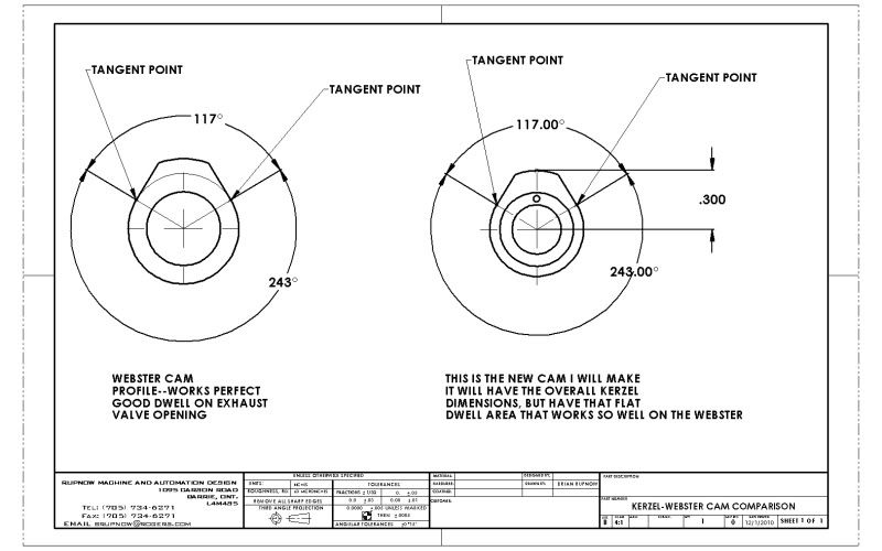
After a day of mulling this over, I have arrived at the following conclusion. The theoretical 90 degrees of exhaust profile on the cam is correct, but it doesn't make allowances for valve lash, nor does it allow for opening the valve 10 to 15 degrees before bdc and keeping it open untill tdc. Again, I keep going back to something I have built, that I know the parameters of and that works---namely the Webster. I went back and checked the profile of the Webster cam (which I had created in 3D at the time I built it), and was quite surprised to see that it had a total of 117 degrees of exhaust profile. Now if I consider my theoretical 90 degrees, plus 7.5 degrees for opening the valve 15 degrees before bdc, that brings me up to 97.5 degrees. Where does the other 19.5 degrees come from?---Well, perhaps some allowance for valve lash---I don't know, as the Webster cam was originally created by Mr Webster (I assume) and I just used his geometry data to build the solid model and the cam. I know it works well, so I will copy that same 117 degrees of exhaust profile and see what happens.
KERZEL-WEBSTERCAMCOMPARISON.jpg
 
Maryak said:
Brian,

Have you taken into account the type of contact between the cam and the cam follower ??? As I understand, if it's not point to point e.g. a flat follower, then the cam has to be altered to allow for this.

Hope this helps.

Best Regards
Bob
Maryak--The webster cam rode against a flat pivoting lever which opened the exhaust valve by pressing on the end of the valve stem with the other end of that pivoting lever. The ratio of lever from one end of the lever to the other was very close to 1:1. On the Kerzel engine, the cam acts on a cam follower bearing which is connected to the end of the pushrod which operates a pivoting lever (the rocker arm) and then onto the end of the exhaust valve. Perhaps allowances would have to be made for this difference, but I'm certain I don't know what the allowances are. This is getting into an area of engineering math related to engine building that I have no training in. I am at the point of "Try it and see if it works" engineering. What I currently have doesn't work---I do know that. So---I will try a cam based on something that I know does work. Not a very scientific approach, but I don't really have any alternatives.
 
Brian Rupnow said:
I am at the point of "Try it and see if it works" engineering.
Nothing at all wrong with that. It adds an element of fun, and afterall, thats why we do this. ;D

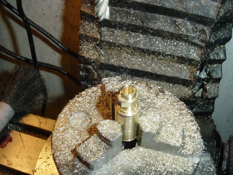
That cam looks good, brass parts are always prettier.
 
Hi Brian
Brass does look great but wont it wear even on a hit and miss?
not long now, will it be today?
Pete
 
Brian,

Have a look at http://modelenginenews.org/

Search for:

CamCalc

Last update: March 22, 2007

This page will generate a table of lift figures for a harmonic cam from values entered in the fields below. The lift table is used in machining the cam profile by the milling method (see Page 7 of the Feeney Construction series for a description of this process). The following links provide more detailed information. The links from the parameter labels explain what is required for each.

Some brief notes on how this all works.
A (thankfully) brief technical explaination.
The Effect of Tappet Clearence.
Source Code for the Terminally Curious.
Acknowledgements on the genesis of this tool.

Hope this helps as well.

Best Regards
Bob
 
Bob, have had that cam calc saved in my favourites for years, keep meaning to have a look at it.

Brian, refer to Gail's post above, on his tiny engine it only took 0.010" lash to equate to 11 cam degrees but he says roller followers are more susceptible to lash.

Good luck with your latest profile.

Nick
 
NO JOY!!!!!! The new cam does make the engine fire more consistently, but it still won't run on its own, with either carburetor, my home built one or the Traxxas Pro15 carb. I may try something like propane for fuel, just for giggles, but ---I still have no compression. Next step (and about the only thing left I haven't tried) is to build a valve seat cutter like Chuck did. After that, if it still has no compression and won't run, I'll set it up on the shelf beside Zee's train, and never machine anything again!!! :'( :'( :'(
 
Stick a funnel on the carb inlet and put a stout fan blowing into and try again. Get it running for more then a few pops and it may help the valves to seat.
 
Brian, another pretty easy thing to try is a vapor fuel tank instead of the carb. They are really easy to build and seem to be a lot more forgiving than a carburetor.

9d8d3c72.png


Chuck
 
Lakc--Tried your method---Doesn't work at all on these small engines, at least not for me. Chuck---I tried it on Propane this afternoon----Same as gasoline---It fires right along, runs great then coasts to a stop as soon as I shut the drill motor off.
 
Tough luck there Brian. Compression is undoubtedly very important. Some more information seems to be in order, I would suggest a leakdown test. Removing the spark plug, making an adapter for air pressurizing the cylinder at TDC, you should be able to hear where the air escapes from.
 
Brain i can't remember if you did this or not, but did you try using valve grinding compound and an a drill to get your valves to seat. I'am sure you thought of this.
 
Bronson---I did lap the valves with valve grinding compound---By Hand. You NEVER EVER use an electric power tool when lapping valves. All that does is gall the stems and burn the faces off the valves and seats.
 
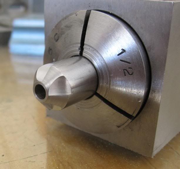
Chuck---This may be my next step. There's nothing else left!!! I bought a foot of 3/8" drill rod when I bought the 1/4" drill rod to make the valves---Thinking of course that I might have to build a valve seat cutter like you did. I don't have much if any experience with drill rod. I do have carbide lathe tooling and some carbide boring bars, but no other carbide tooling. Can I drill and ream drill rod (0.093") and end mill the four "facets" with conventional HSS tooling, sharpen it with a small grinder like you did, then harden the drill rod by heating it cherry red and an oil quench? I've got the engine to a point where there is no "bind" in the bearings at all, and I feel absolutely no compression when turning it over by hand. I know the rings are good, because when I bolted on a solid "blocker plate" with a gasket in place of the cylinder head, it would kick back under its own compression quite readily when I tried to spin it by hand. I've got it to the point now where it will run by itself for 10 to 15 seconds, then just gradually die out, similar to what fuel starvation would do, but I know its not fuel starvation---does the same thing with two different carbs. Its SOOOOOOOOOO close!!!!
Chucksvalveseattool.jpg
 
Just tossing this one out there but could the valve springs be to light. If the spring pulled a little harder maybe the valves would seal some more.

Could the exhaust valve be being pulled open on the intake stroke? I dont know!!
 
Back
Top