Brian Builds the Kerzel Hit and Miss I.C.

Home Model Engine Machinist Forum

Help Support Home Model Engine Machinist Forum:

This site may earn a commission from merchant affiliate links, including eBay, Amazon, and others.
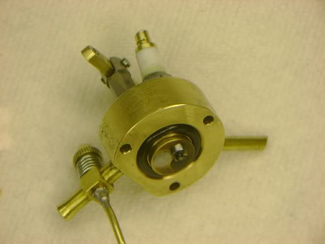
There we go---All muffled up!!!!
muffleronengine001.jpg
 
Progressing nicely Brian, I'm still trailing waaaay behind, but it's starting to take shape

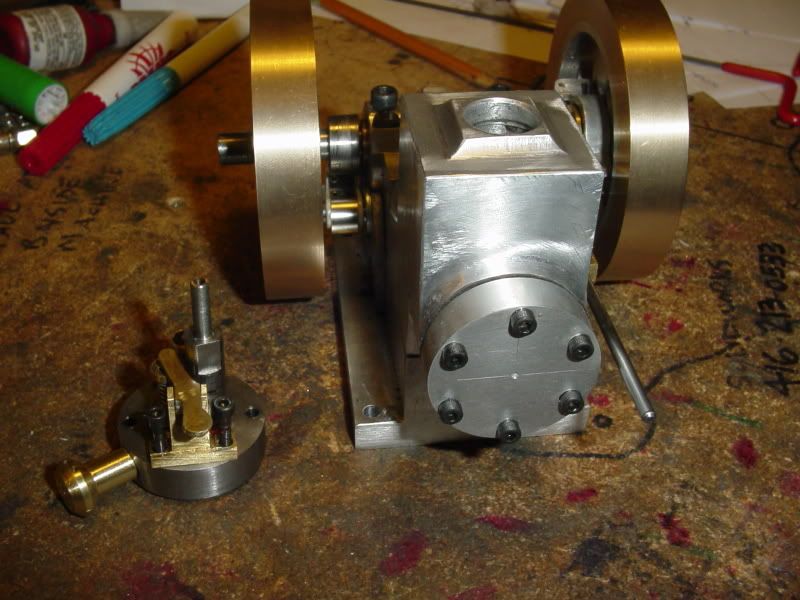
bearing caps.jpg
 
Thanks Brian, the 'glass' tube is the modified body of a Nicorette inhaler capsule.
 
I spent an hour and a half playing with my Kerzel this evening.----Don't laugh!!! In a final attempt to get some compression without having to make new valve cages, I took the valves out and refaced them and relapped them. Didn't work. Still no appreciable compression. I know the rings are good, as proven by the "head off thumb over end of cylinder, spin the crankshaft suckability" test. I can't imagine anything else other than the valves leaking. I have a good quality head gasket made from gasket material on it, and its not leaking there. I would try and start the engine and see how it runs with little (almost no) compression, but it has to have enough compression to at least pull the intake valve open to get fuel, and its not even doing that. I ran it with the electric drill to see if perhaps a little speed would make the intake valve open----No joy there, but I did find out my governor weights and arms and spool are all moving exactly the way they are supposed to. The Kerzel arm still needs a little reworking, but it is propping the exhaust valve open when the governor weights fly out.( I have an elastic wrapped around them right now---I haven't been able to find the right springs yet to hold the governor arms "in" at low RPM). I will try a lighter spring on the intake valve later this week. Something that is rather encouraging, is that I put an adapter in the sparkplug hole which I can hook a small plastic tube on. With both valves in the normally closed condition, I can't blow thru the tube---(at least not very much). As soon as I manually depress the top of either valve, I can blow through the tube. This tells me that things seem to be sealing inside the cylinder quite well. Maybe an engine this small just doesn't have a lot of noticable compression??? How about all you fellows that are building the "Tiny"---Can you feel compression on it when you turn the flywheels? Gotta go watch Jeapardy with the wife now.----Brian
 
Brian,
You should be able to feel compression starting at about 1/3 of the piston stroke. I have gone to a lapped piston on my "Tiny" so it is more free than with the o-ring piston I had in it, but it felt the same way with the 0-ring in it. Coming up on compression stroke, I can flip the flywheel hard enough to make it up to about half stroke and it will bounce back around 180 degrees and bounce again back to the start of the compression stroke. I would not expect the Kerzel to do that with the added friction of the 0-ring, but you should see some definite bounce if you flip the flywheel. My Tiny has 5.6:1 compression ratio at the moment. I put in an extra head gasket which lowered to to just under 5:1 early on when I was having overheating problems. Could not tell any difference in running or the way compression felt. The Kerzel would probably run at anything over 3:1. Not that it would run very well, but it would run. And you would be able to feel compression.

What I would try is to slip a small 0-ring over each valve so they will provide a flexable seal between valve and the valve seat. Then test for compression. It sure sounds like you have leakage some where in the head area and that normally means a valve leaking.

I have followed along on some of the valve fitting methods that have been mentioned in this thread. My personal opinion is that the smaller the valve seat the better. On my Tiny, the valves were turned in on piece and just lightly polished with some 800 grit abrasive paper while still in the lathe. No more than 10 seconds or so. Just enough to get any possible high spots off. The valve seats area is only a few thou wide, probably 0.003 to 0.005. Just enough so I could see it. After drilling the area behind the valve seat out and reaming the guides in the head I coated the area for the valve seat with a permanent marker so I could see when I started cutting. I used a 90 degree countersink kept raising the table until I could see the marker disappear using a Lupe to watch the seat. Then leave it alone. No lapping or polishing. A very narrow seat is much easier to make seal and on a low performance engine such as this valve overheating just won't happen so no worries about getting the heat into the head with a large contact area.

Gail in NM
 
Brian, My Upshur farm engine which has a .750 Dia bore has very strong comperssion when I try to spin the flywheel on the comperssion cycle. I have no rings on the piston just a clean fit. I will try to get a video of the compression

Dave
 
While I was concentrating on the valves in the above post, there are several other possible leakage areas that the tests you have performed might have missed. A leaking head gasket would still have allowed you to pass the thumb over the end of the cylinder test. Spark plug gasket not sealing. Can happen if the plug seat is not square to the threads. Or the spark plug it's self might leak, but that is hard to imagine the way Kerzel designed the plug.

Gail in NM
 
Brian,

Time for a leakdown test. Cobble up a way to put compressed air into the cylinder and listen/use cigarette smoke to see if any air is leaking past the valves or the head gasket. Even an aquarium pump should suffice for an air source, but a double gauge set like an automotive one is obviously better.

If you think it may be rings, perhaps the bore is distorting when the head is bolted on, you shoot a liberal amount of 40wt engine oil into the cylinder, that should provide a good temp seal.

Think of ways to measure what the problem is, make good tests, then act on that information. The hardest things to fix is always your own car/equipment/engine/creation, because your often just too close to it. :)
 
Brian, I feel your pain. Been through it a few times. I finally came up with a procedure that I follow on all my new I.C. Engines.

There are four areas that can cause compression or lack of compression problems.
1) Seal between piston & cylinder
2) Seal between head and cylinder block
3) Valve leakage
4) Spark plug leakage.

1) To check the seal between the piston & cylinder I make a flat plate and gasket with the same bolt hole pattern as the head and secure it to the cylinder block. This seals the cylinder eliminates any problems with valves, spark plug, and head leakage.

I then give the flywheel a spin. It should not go through a complete revolution, but bounce back almost half way through the other direction. If this happens, you have a good enough seal for the engine to run.

If the flywheel spins through a complete revolution, you have ring leakage and must install new rings. I sometimes will even add an o-ring behind the metal ring.

If the flywheel does not go through a complete revolution, but does not bounce back half way through a revolution, the rings are too snug or the o-ring is to tight.

You can put a threaded hole in the plate and check compression with a gage like you would in an automobile engine.

2) To eliminate any leakage between the head and cylinder I add an o-ring to the head and allow about .010 compression on the o-ring. I do this on all of my engines now to eliminate that problem.
HeadAsmIn.jpg


3) This is the most difficult area to solve. The one thing that helped me the most was when I started machining my valves in one setup. I think I recall reading that when you made your valves, you turned the stems and then cut the material to length. Later you set up the valves again and machined the valve seat. If you setup in not absolutely perfect, you might have enough eccentricity to cause leakage and maybe enough that you can't even lap the valves in.

When I machine my valves now I set the compound at 45* and first make my valve seat cutter. Next I will machine the stem on the valve. It really helps if you can use a small live center to support the small stem. I then change cutters and while running the lathe in reverse I cut the valve angle on the back side. (did the same on the seat cutter) Then the valve can be cut to length. In most cases I don't even have to lap the valves in.

When I cut the valve seats in the head, I drill, bore or ream the hole for the stem and then cut the seat in one setup. Then move to the next valve seat and machine that one complete in one setup.


4) If the leakage is around the spark plug, a soft copper washer will seal it.

On the exhaust valve, I use a fairly heavy spring. It may add a little ware on the cam & lifter but I don't run my engines that many hours to notice the difference.

I try to have a very small seat area on the intake valve. I use just enough spring to close the valve and rely on the cylinder compression to seal the valve.

Don't know if any of this will help you but it does work for me.

Best of luck solving that problem and look forward to seeing the engine running soon.
 
Our club recently held a model Judging competition and I was talking to one of my fellow club members who was building a Chenery V Twin from Hemmingway Kits http://www.hemingwaykits.com/acatalog/Aero_Twin.html

He'd just finished it that very night (although not tried starting yet) and was showing me some of the features. He, like Gail said that valve seat area was best kept to a minimum to give the best chance of getting a good seal. There was a very noticable compression with his engine when turning over by hand.

It got me thinking though, why does the valve seat need to be cut at an angle - why cant it be a very square edge, then with a tiny (few seconds) bit of lapping it would create a perfect seal. I know the poppet type valve on the regulator of sweet pea locomotive is like that.

People might think that there would be a tendency for the valve to lift - but why would there? Surely there would be much more force pushing the valve shut than there would trying to lift it due to the much larger area on the top face of the valve?

Maybe Gail or other any of the other experienced guys will shoot this idea down in flames though?

The subject of sealing valves also came up on Steve's V8 build and he said he doesn't lap at all - just uses the same setting on top slide to cut both valves and valve seats, as long as a good surface finish is obtained they should be a perfect match.

Nick
 
Nick,
There is nothing wrong with your idea. I talked with someone at NAMES, maybe 10-12 years ago, that advocated doing just that. As I see it there are two possible problems with it.

1. If the pocket geometry that the valve seat is formed on is not perfectly round and centered on the valve spindle, then it valve may deflect a little bit when lapping in as there has to be a little clearance for the valve spindle in the valve guide for it to work.

2. The working surface of the head must be perfectly perpendicular to the valve spindle or valve will be deflected when lapping.

Both problems can be easily overcome with care. The first is taken care of by using an end mill to open up the pocked for the valve. The end mill will act as a boring tool and while it may not leave a accurately sized hole, the hole will be round. The second is taken care of by surfacing the head working surface with a skim cut at the same set up as the valve spindle holes are drilled and reamed. Then remove any tooling marks on the head afterward with abrasive paper on a surface plate or other flat surface.

If using valve cages, then the problems fairly well go away if the valve pocket is bored out after drilling and reaming the valve guide portion. A reamer would probably work also. In either case, then surface the working face to remove any chatter marks from the start of the boring or reaming operation.

My use of a counter sink is to try to accomplish the same thing in a manner that is easier for me. I do use an end mill to put the pocket in so I am starting with a round hole and the countersink is used at the same setup without moving the table on the mill. I use a very sharp countersink, carbide, to minimize the tooling marks that might be left. Even if there are some they will be annular rings that really won't make any difference. Above I said I am making a few thou wide valve seat. What I do in practice is after marking the seat area with a marker I just run the counter sink in far enough that I can see a bright ring all the way around the hole. Then I quit and am done.

Gail in NM
 
Thanks again Gail for yet more useful information.

So am I right in thinking your valves sit slightly proud rather than being almost flush with the cylinder head? I wasn't sure when you initially said you made the seating area thin, whether you had sort of 3 angles like a racing valve.

I think using your technique with a decent cutter people will have a high chance of getting a good seal, it is certainly what I will be doing.

The more I read these posts, the more I just want to stop my current projects and start an i.c. engine but I've got to finish them first really. :-\

Nick
 
putputman said:
1) To check the seal between the piston & cylinder I make a flat plate and gasket with the same bolt hole pattern as the head and secure it to the cylinder block. This seals the cylinder eliminates any problems with valves, spark plug, and head leakage.

Putput---I will do that tomorrow.---brian
 
Well, the "proof of the pudding is in the eating" as the saying goes. This morning I made up a blank plate drilled with the cylinder head bolt pattern and installed it on the engine with the head gasket. The engine has all kind of compression, and will 'kick back" if you grab the flywheel and try to give it a spin. This conclusively proves it is non sealing valves causing my lack of compression. Next trick will be valve cages A'la Chuck Fellows.
FALSEHEAD002.jpg
 
Good method of diagnosing the fault Brian - getting there now.

Nick
 
Brian, don't know if you saw my later post about making a valve cage, but I believe drilling the initial pilot hole all the way through the blank is not the best way to go. I think this may allow the small bit to wander to one side.

An article written by Dwight Giles in Model Engine Builder, issue #20 suggests first creating the valve port opening to finish size, then cutting the valve seat 1/64th - 1/16th inch wide using a boring bar and the compound, then finally center drilling and creating the hole for the valve guide, all without removing the piece from the lathe. The article suggests drilling the valve guide to around to 1/64" undersize, then boring with a small boring bar to .003"/.005" undersize, then reaming to finish size. He suggests using a solid carbide micro boring bar as short as needed to do the boring. However, these things apparently cost $35 apiece so I don' think I'll be doing that.

Chuck
 
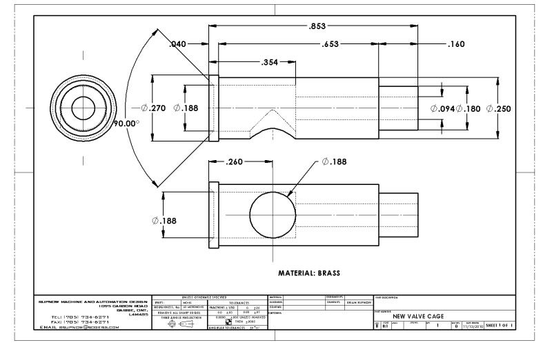
I had the very best of intentions for the afternoon----Went to my steel supplier and bought a foot of 1/4" drill rod, and a foot of 3/8" drill rod, and a foot of 3/8" dia. brass, then ended up with a housefull of grandchildren all afternoon, so my intentions remained that----only intentions. Chuck---I did see your posts over on the Troubles-troubles thread. If I understand you correctly you are saying drill the large part of the bore first, then the seat, then the thru hole, then ream. I do not have boring bars that small, and don't really plan on buying any. My smallest center drill/countersink is .187" diameter, which coincidentaly is the diameter of the largest bore in my valve cage. I am working with the assumption that the hole through the side gets drilled AFTER the cage is pressed/loctited into the head?
NEWVALVECAGE.jpg
 
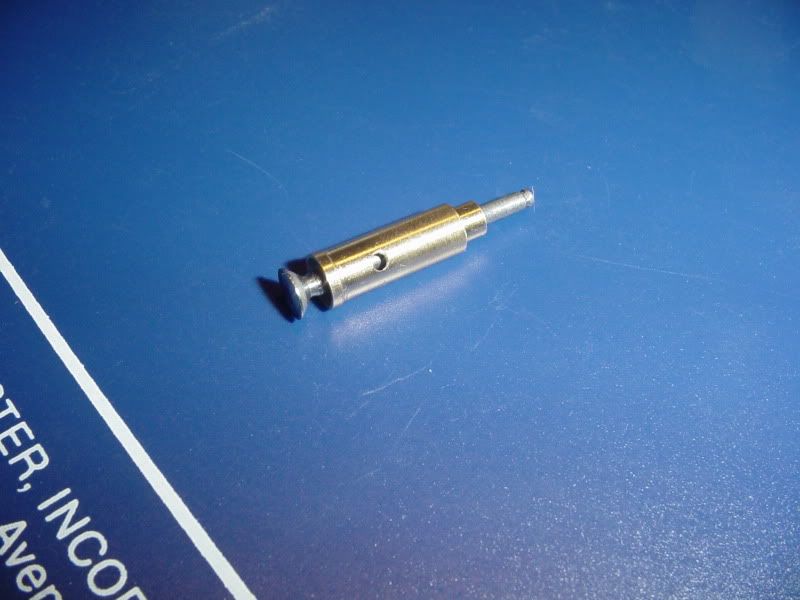
One more time, with feeling!!! And yes, I had to drill that .070 hole in the side of the cage and try the "blow your guts out" test to see if the valve was sealing in the new cage or not. Of course, I couldn't tell---only suceeded in pinching my lip between the valve and the cage. When the cage is loctited into the head and set for 24 hours that hole will be enlarged to 3/16" (It lines up with the port in the head).---cross your fingers for me!!!
VALVEANDCAGE001.jpg
 
Looks good. One thing you might try before you install it. Use a felt tip pen or marking dye and color the valve seat all the way round. Then put the valve in, and pressing it lightly against the seat, turn the valve several times in the seat using the valve stem. If the color is worn off all the way round or not at all, you probably have a good seat. If the color is worn off in one spot, you probably have a problem. Chuck
 

Latest posts

Back
Top