Brian builds a Corliss

Home Model Engine Machinist Forum

Help Support Home Model Engine Machinist Forum:

This site may earn a commission from merchant affiliate links, including eBay, Amazon, and others.
for tapered pins something i discovered by accident is just the deflection of turning down a very small thin rod usually produces a slight taper. i just drill a regular hole and then drive the tapered rod into place usually the pin starts in really easy then starts getting tight before i start pecking it to "drive" it on in. then cut off the excess on both ends. sometimes i use lock tight on them as well but usually the taper in the regular hole is more than enough to keep them in place. i guess this is probably considered as "crude" but it works great for me.
 
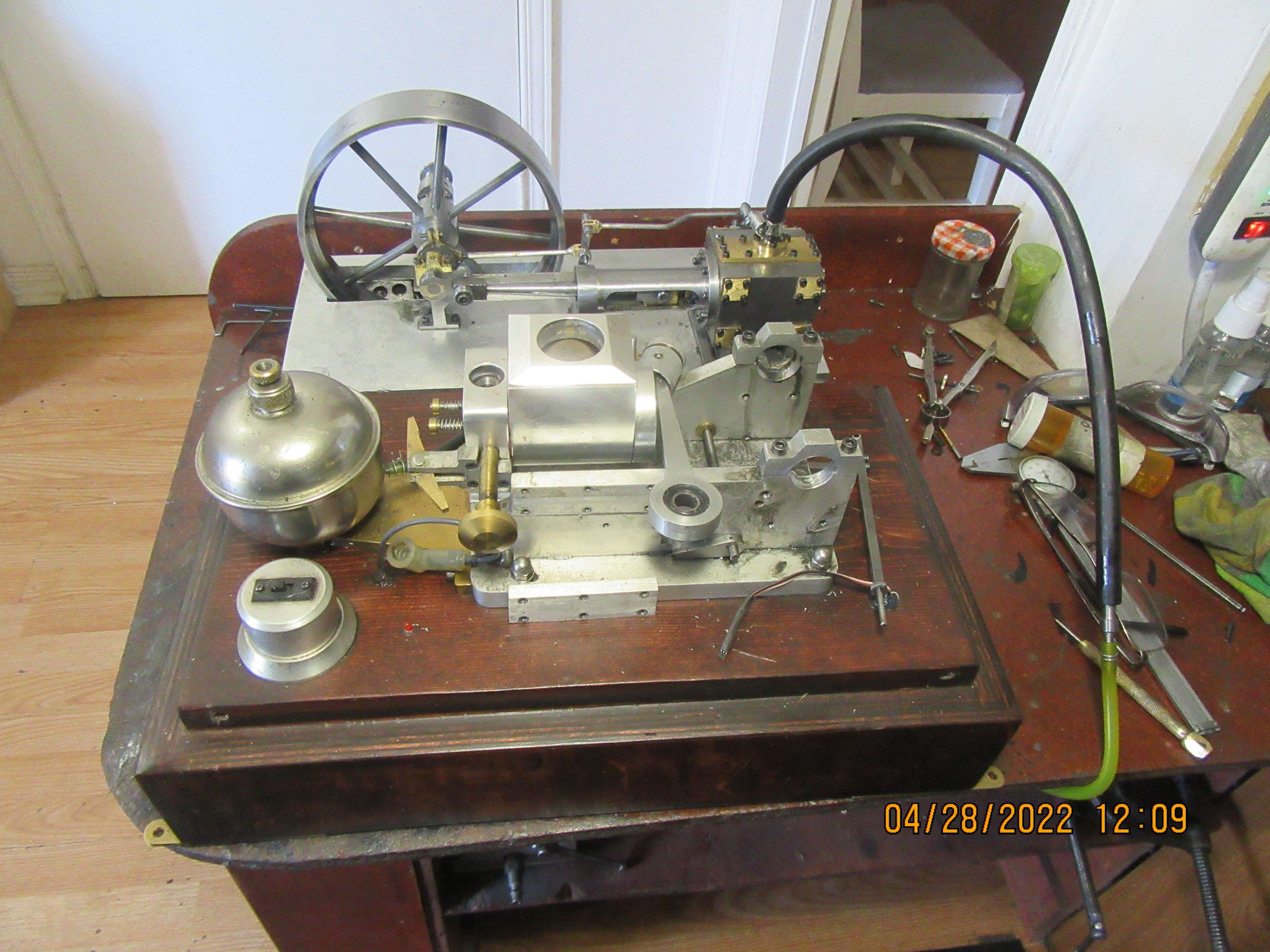
This is my third and final video of the Corliss engine I have built. This was not my design, but was (I think) designed by someone from Namibia. Some of the smaller items were redesigned to suit me and my methods of machining and fabrication. This is the first rotary valve engine that I have built, and yes, it is more complex than a standard slide-valve steam engine. Now that all of the machining and test running is finished, I will probably clean the engine up, paint it, and build a nice wooden base for it. Thank you to all who have followed my build on the model engine internet forums.---Brian rupnow
 
Hi Brian, Why not use a small grub screw in the lever instead of a pin make easy dismantling in the future if it is necessary.
 
Congratulations Brian,

As always, I enjoy your build threads and the ultimate result.

Your continuous learning as you progress on these things is an inspiration.

Thank You for posting,

--ShopShoe
 
I've learned a few new things and had to dig deep into the things I already knew for this one. It is a nice engine, it did have me stumped a couple of times, and it is very particular about it's valve timing. It has filled up 2 1/2 months of cold miserable winter, and given me something interesting to do. I'm very happy that it ended up being a good runner.---Brian
 
Years ago, when I first got into designing and building model engines, I designed and built the "Rupnow Engine". It was a hit and miss engine controlled by a flyball governor. It ran---didn't run really great, but it was a "first" for me. Over the years, I have robbed parts from it, to the point where I will never actually rebuild it.---However, it has a beautiful wooden base, and measurements show that with some careful carving, that base will fit my Corliss engine. I am going to remove the remains of the "Rupnow engine" and try to make the Corliss fit into this base.
zFF6dF.jpg
 
Brian when you have the drawings ready, I would be interested in a set of the plans, sure runs sweet, that will bring me back to my childhood days when I ran one, the one we ran was pulling water from a Bayou to flood rice land it had what was called the snail pump, had two 48 inch suctions that big engine would hardly change speeds when the suction was primed and started pumping, enjoyed the build so much, thanks again for sharing you wisdom with us, Joe
 
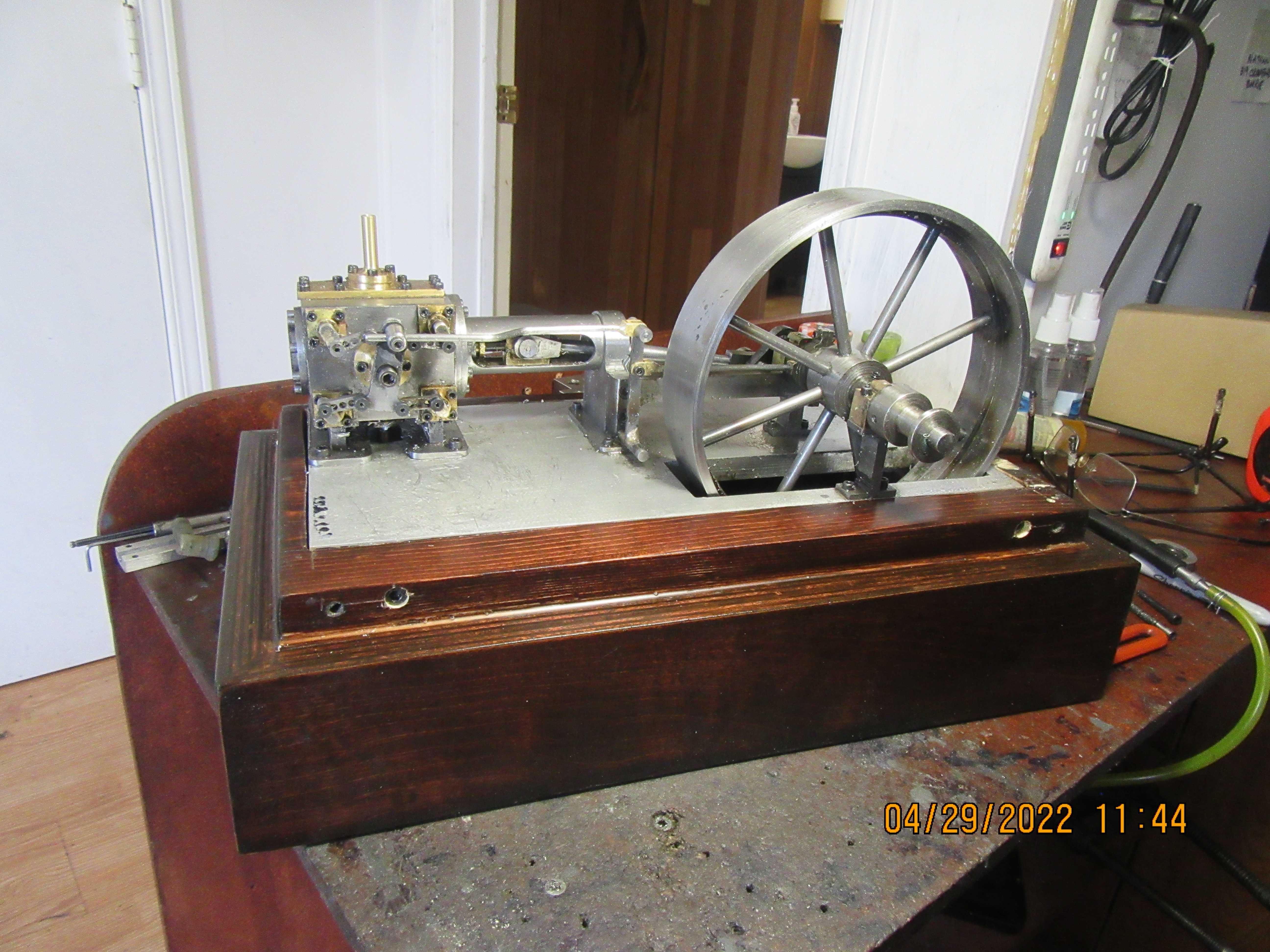
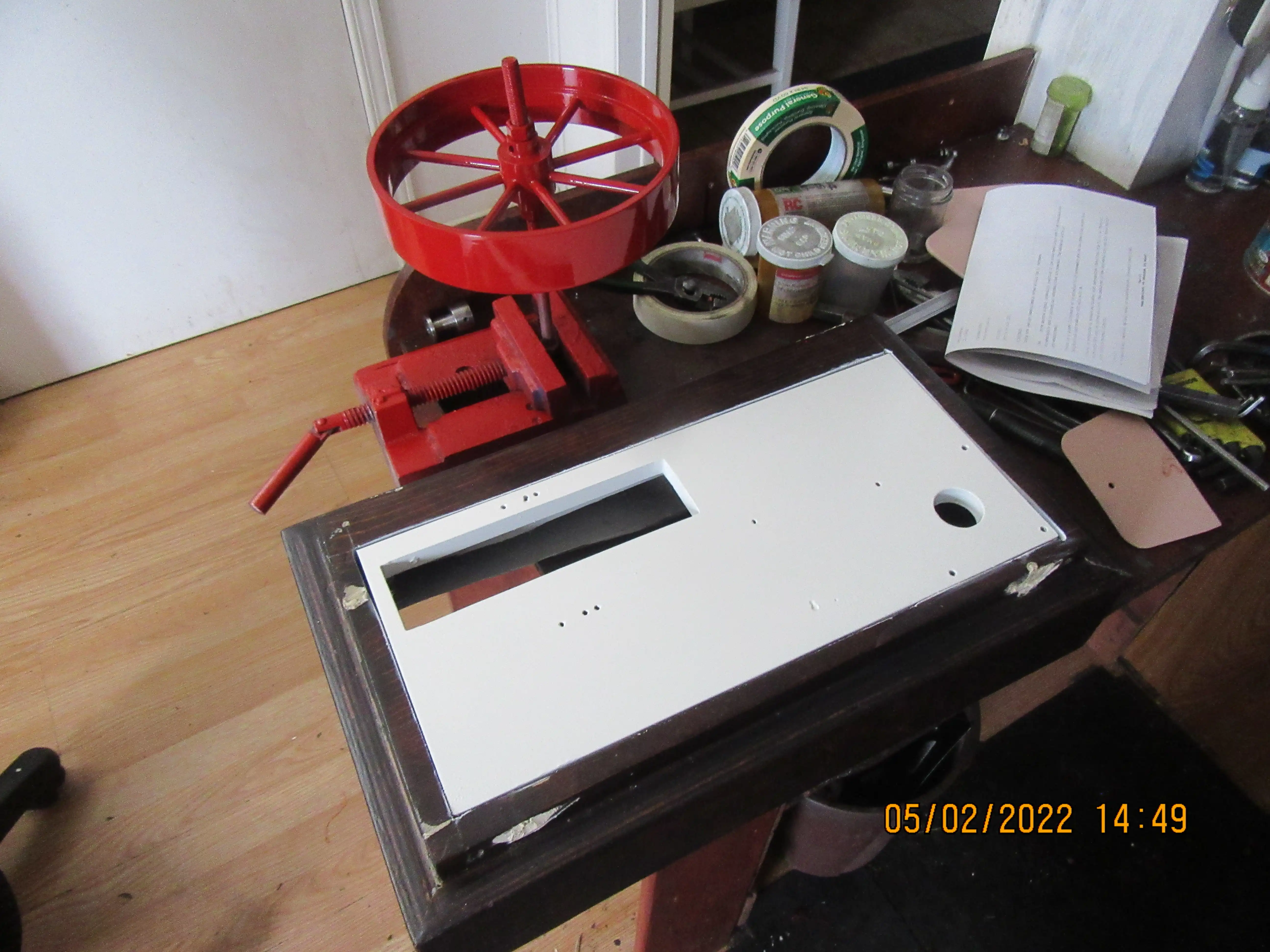
Without a whole lot of extra work, the Corliss engine now has it's own wooden base. Next up will be a bit of "plastic wood" to fill the bolt holes drilled in the side of the base and some caulking around the edges of the aluminum baseplate to make it look a bit more professional.
HXNir6.jpg
 
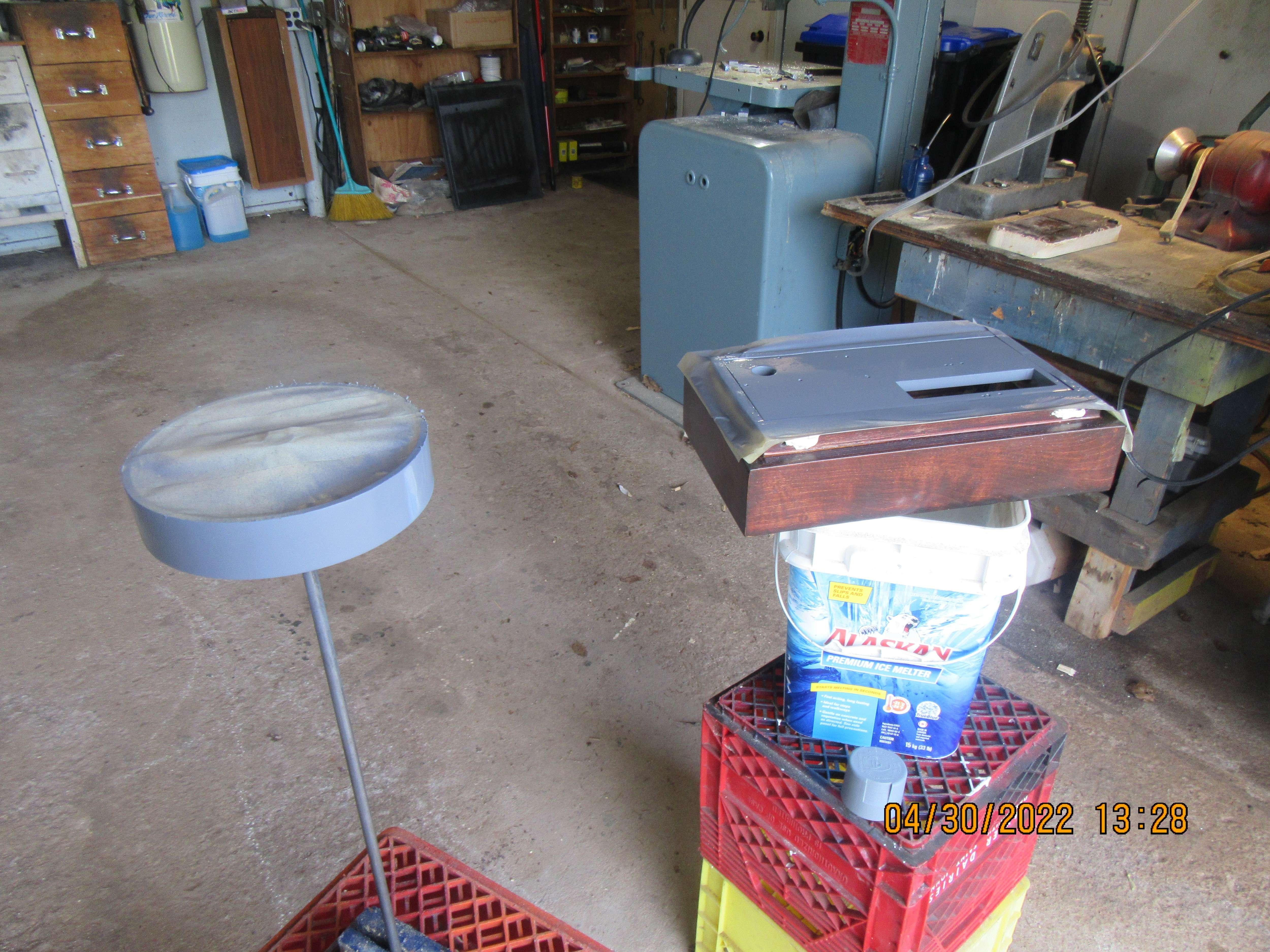
The great "cosmeticing" has began. First order of the day was to prime the two components that I had used some J.B. Weld on to fill holes drilled in the wrong place and fill in holes left from welding the outer end of the spokes to the flywheel outer diameter. These had been filled with J.B. weld previously, and sanded smooth, but I can never tell until I get some primer on there whether the holes
need a bit more filler or not.
iYZQVc.jpg
 
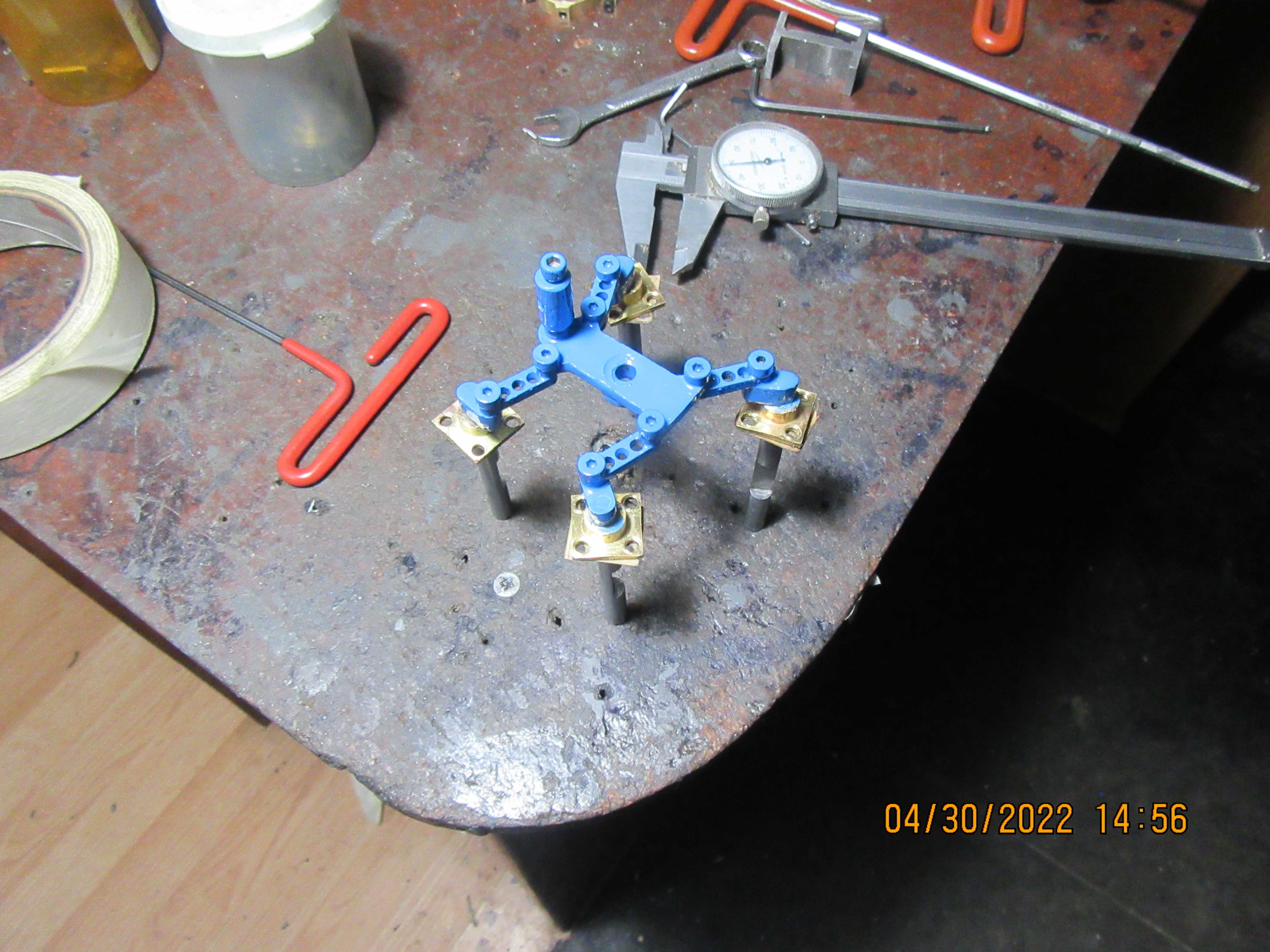
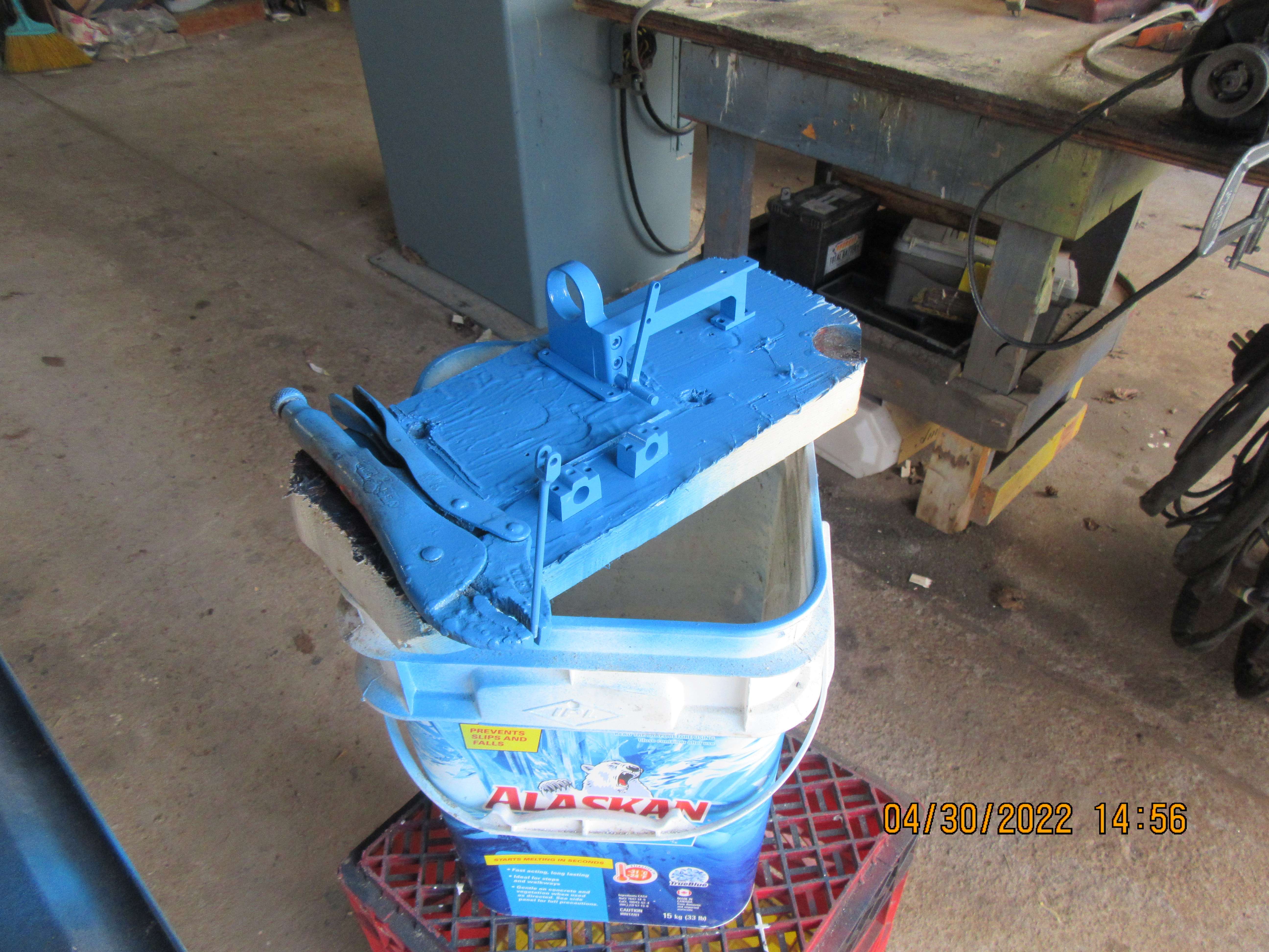
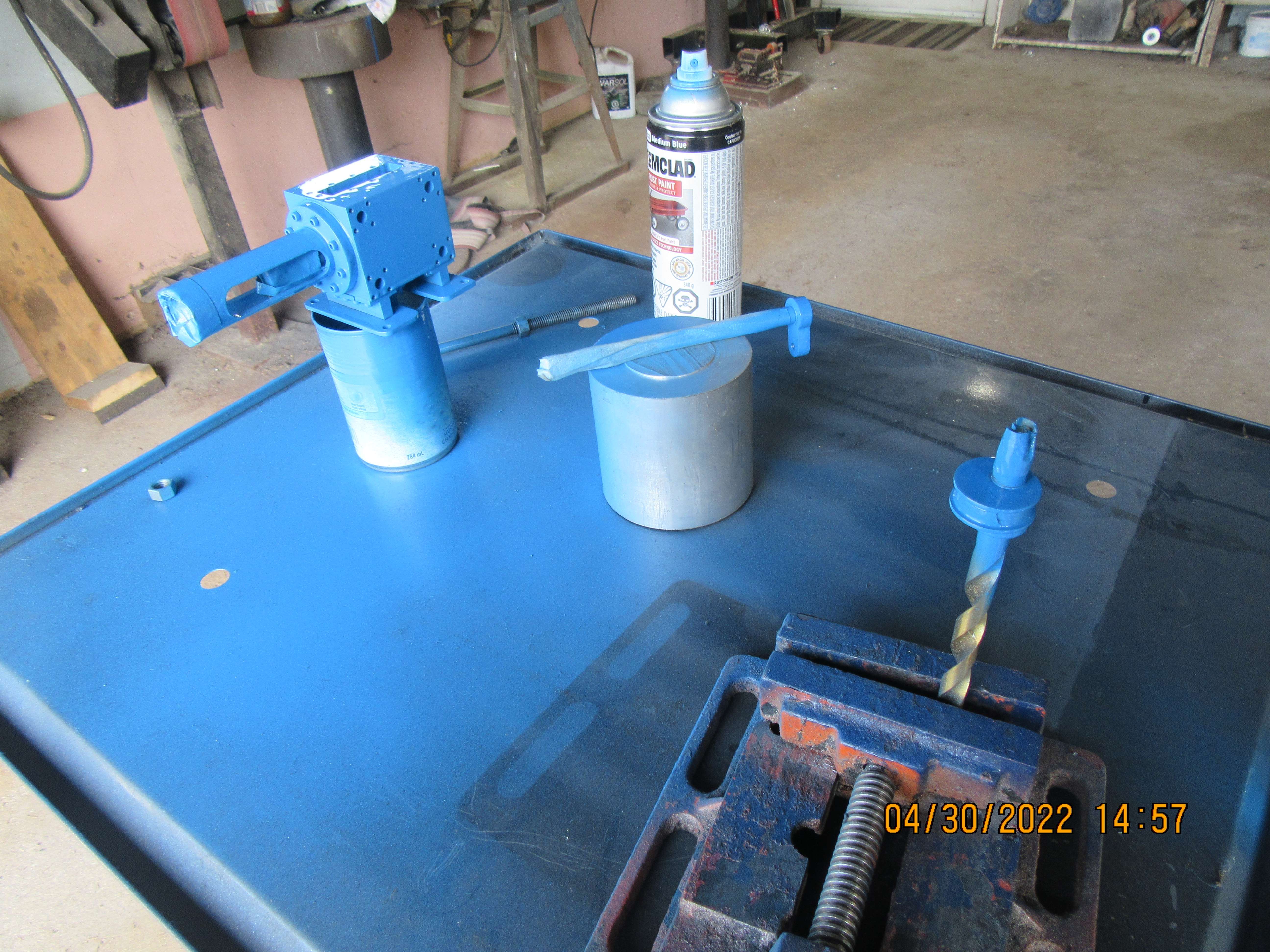
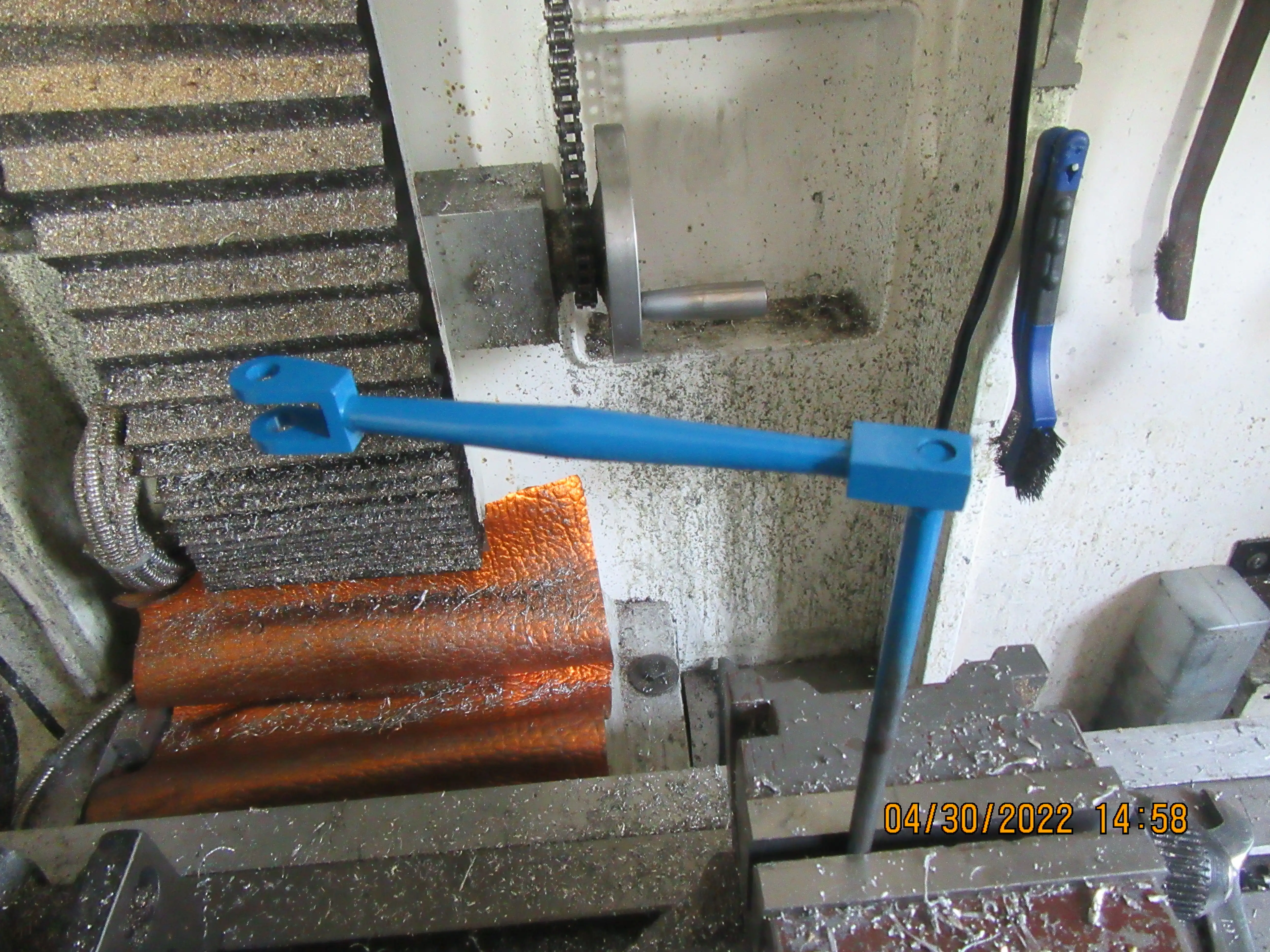
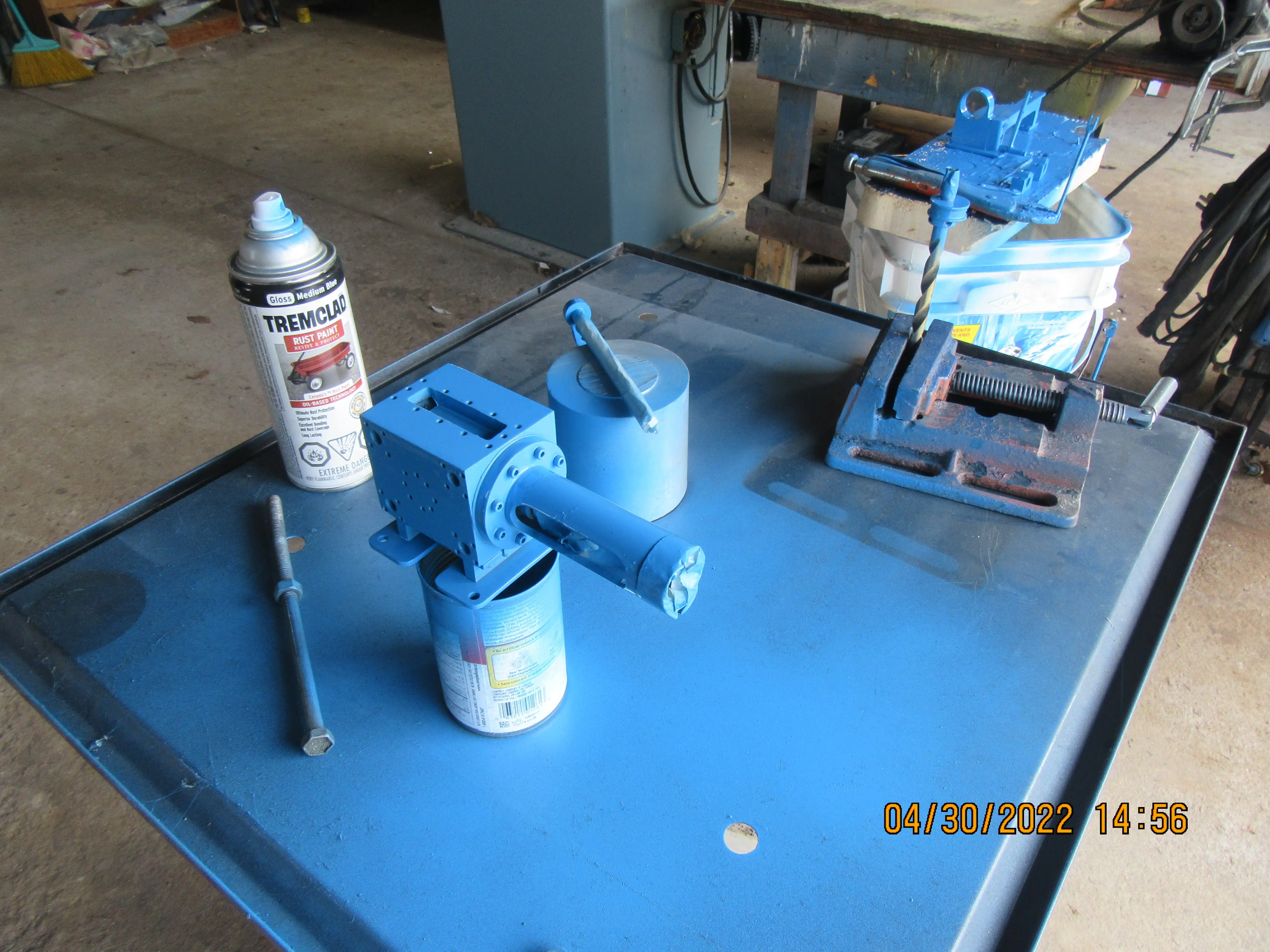
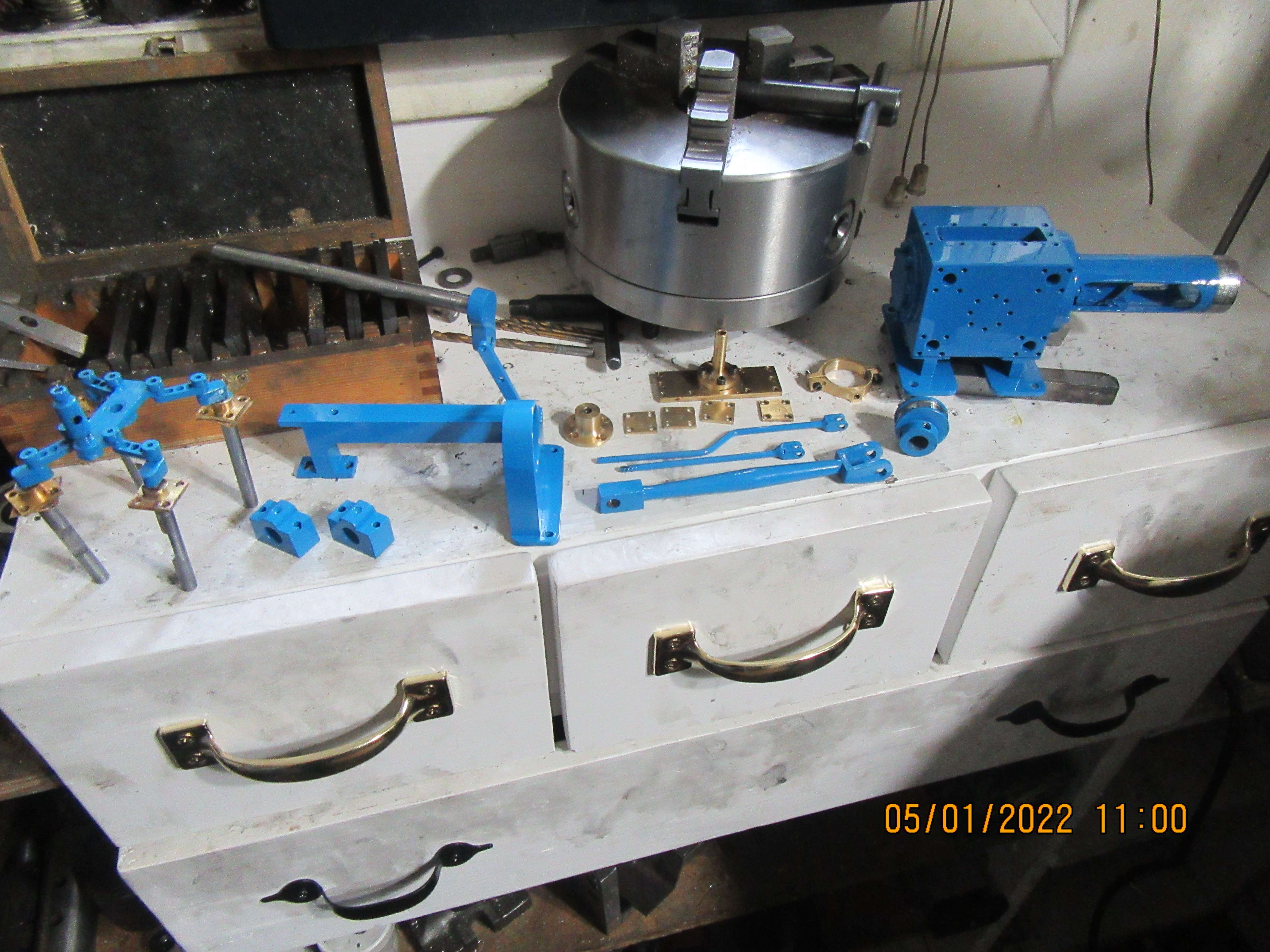
This afternoon I've got the blues---But that's not a bad thing!!! Everything except for the wobble plate and the linkages got three coats of spray on Tremclad enamel. The wobble plate and linkages were painted by hand with a very small art brush. I have one bearing support that I have to add some J.B. Weld to, and I will let that set up overnight so I can finalize the shape and paint it tomorrow.
KbC4zX.jpg

xCtzFL.jpg

PFati5.jpg

6zQr5x.jpg

bHkhZH.jpg
 
I do enjoy the creative ways that you have devised to hold your parts whilst they are being painted. I especially think the blue is a good look on the vise grips. Nice job. Will there be any pin stripping, maybe in red?
 
No, I've tried pin striping in the past. When I get some paint on the brush my hand is steady as rock. By the time the loaded brush gets close to the work, I shiver and shake like a toad eating chain lightning.---No pinstriping.
 
There is pin striping tape or decals that would look sharp on your model. Those are not so subject to the toad effect.
Check out the interweb if interested.
 
All of the engine parts are painted, unmasked, and set up together for a family shot. One bearing stand is missing---I had to J.B. Weld some "oopsies" on it last night and this morning I sanded it to shape and painted it and the paint is still wet. I have not painted any of the brass parts that show. There are a couple of very minor "blems" in the flywheel and engine base, so in about ten minutes I am off to Canadian Tire to buy a small tube of "spot putty" to fix them, and tomorrow I will paint them. Something I have learned over time---Although the paint dried overnight, it can still be marked by too much handling. Far better to let it set up for three full days before trying to reassemble everything.---Brian
FMtxrH.jpg
 
Today was my day to run around to different doctors offices getting lined up for physio, x-rays, meeting with surgeon, yada, yada, yada. Yesterday I spot puttied and primed the engine base and flywheel and painted them. This afternoon I took off the masking tape and paper. I'm happy with the results of my painting.
4hQKdn.jpg
 

Latest posts

Back
Top