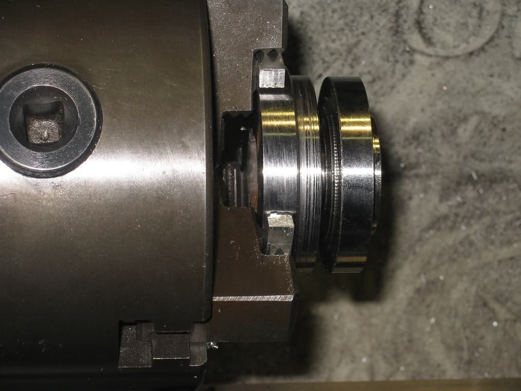
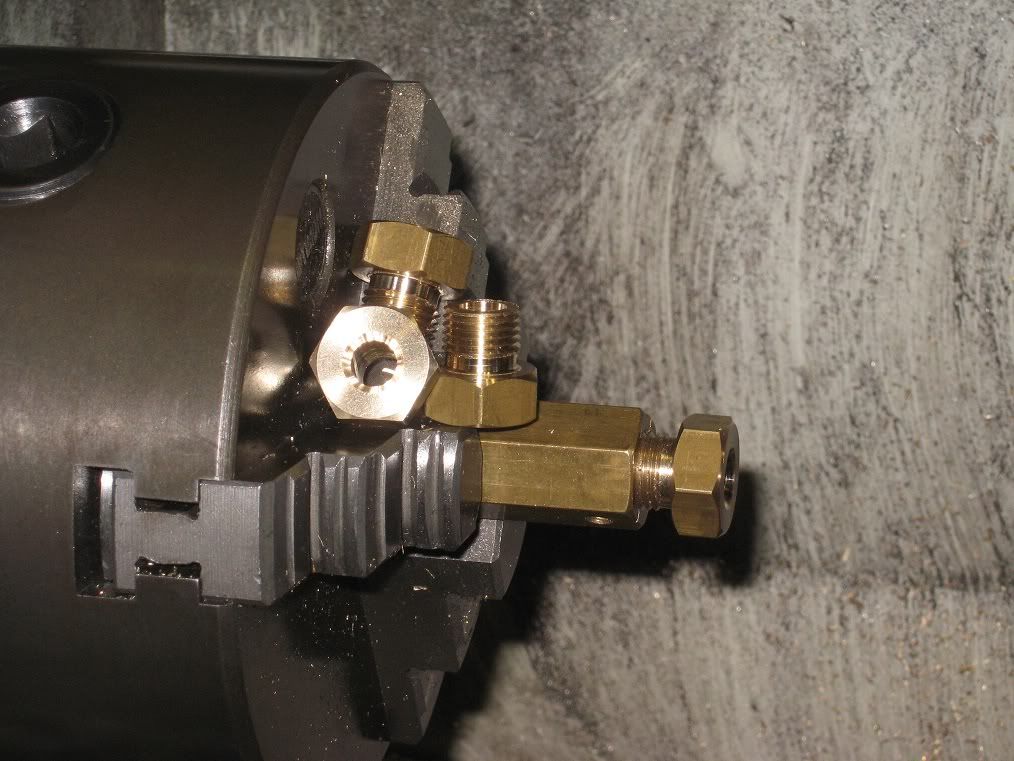
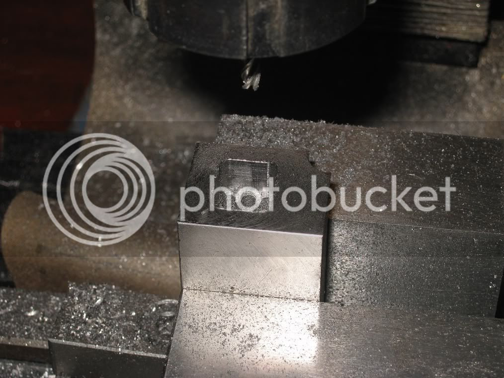
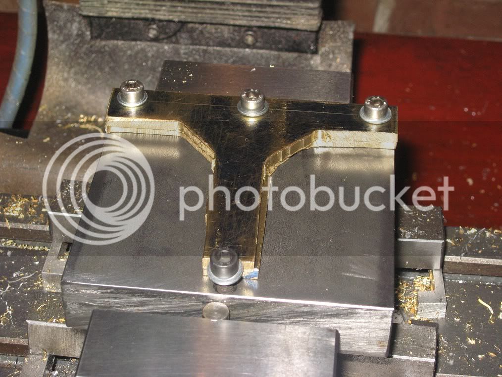
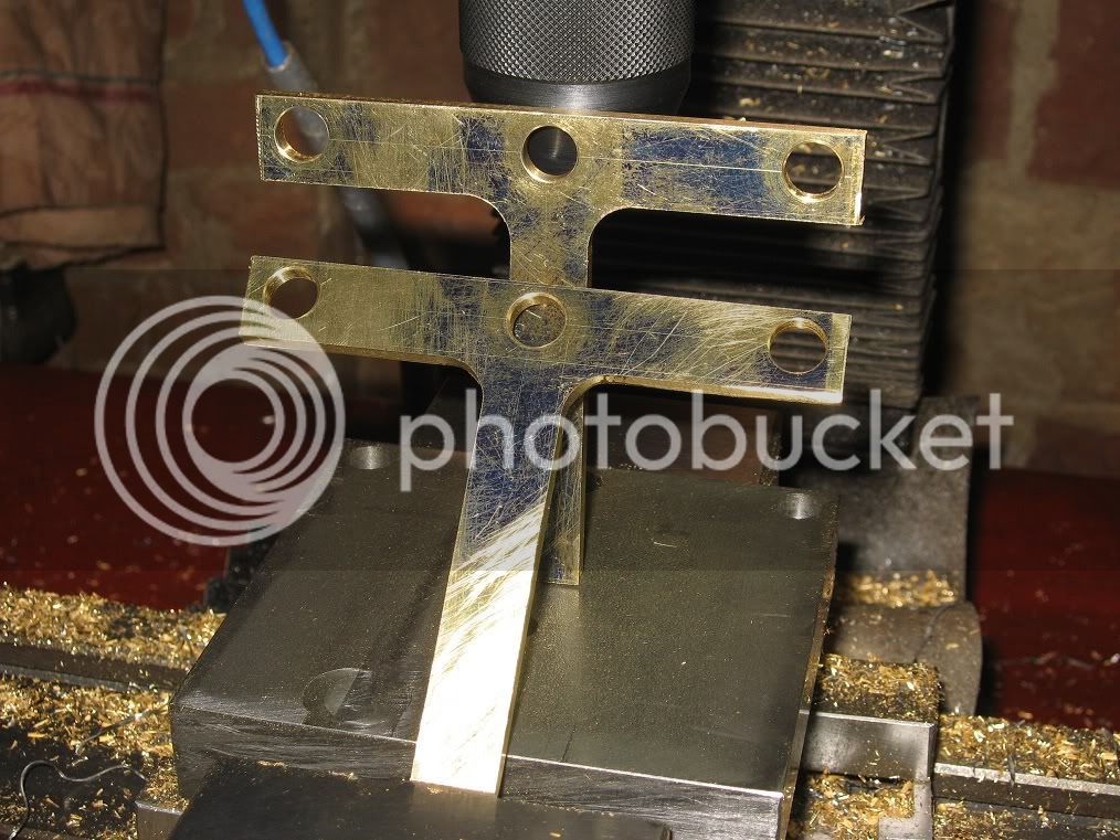
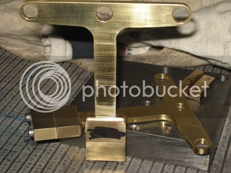
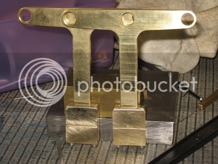
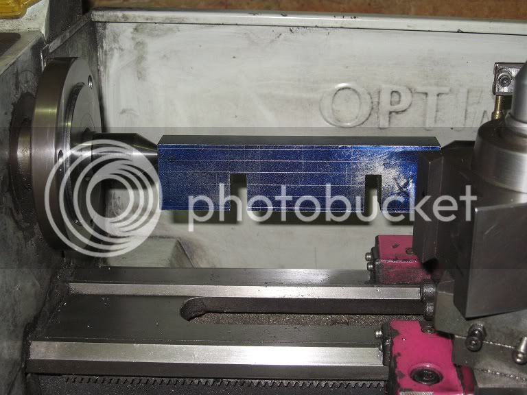
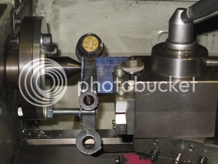
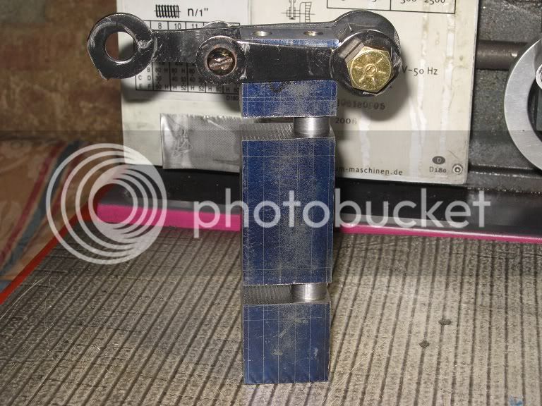
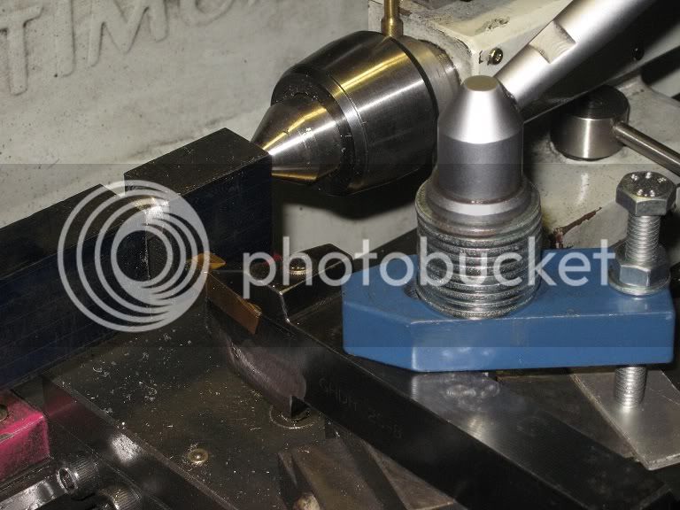
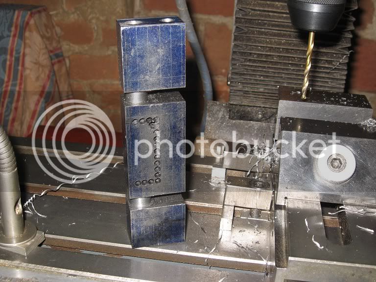
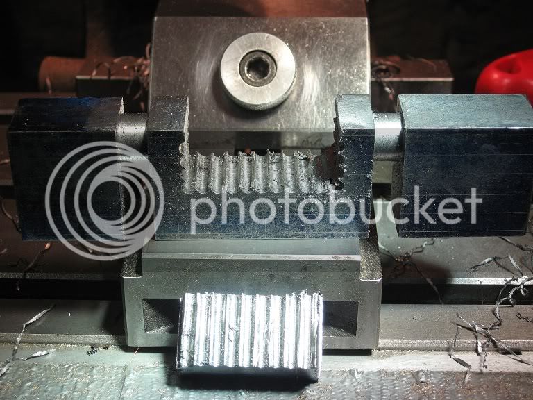
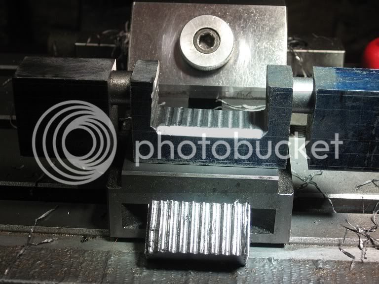
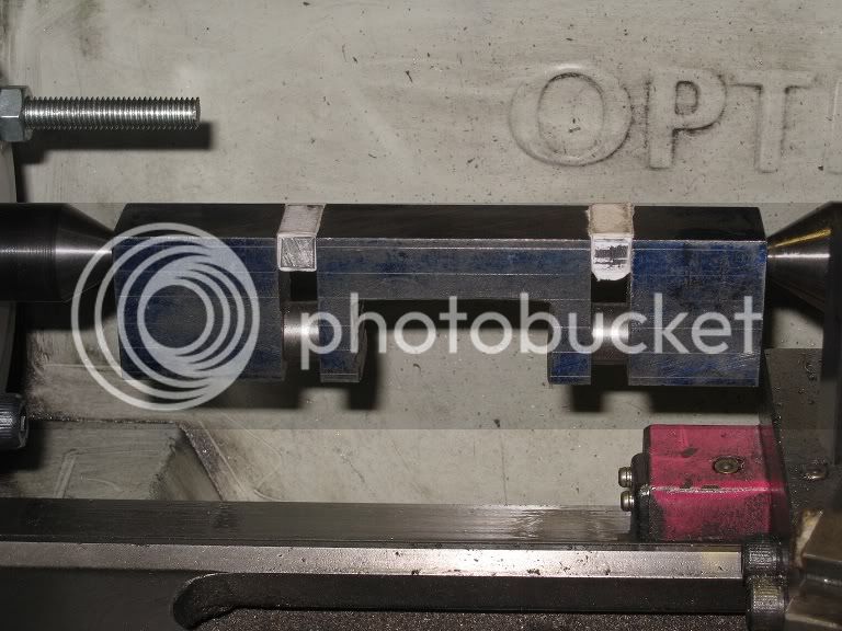
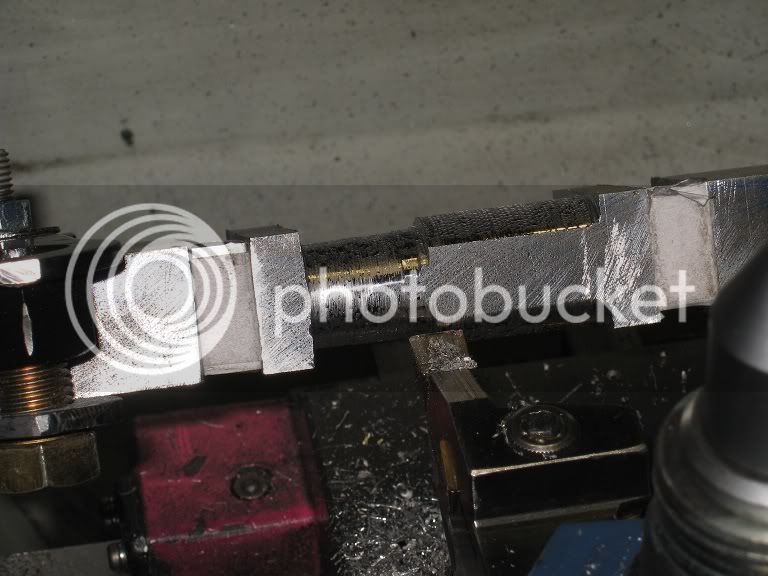
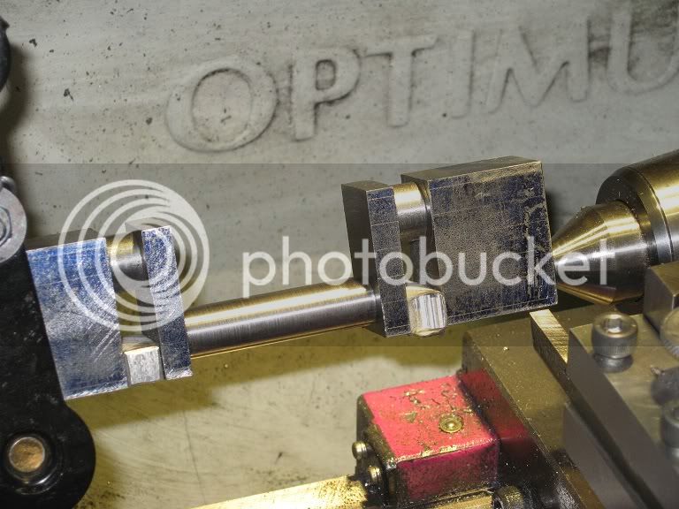
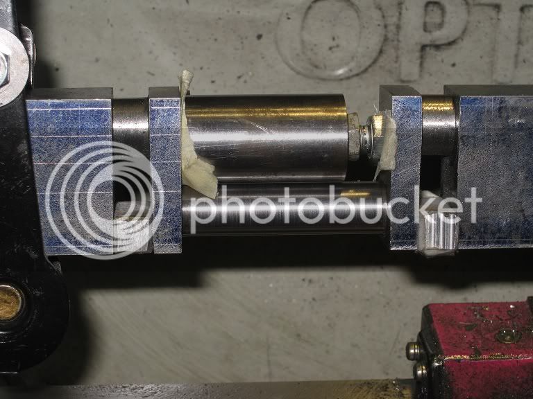
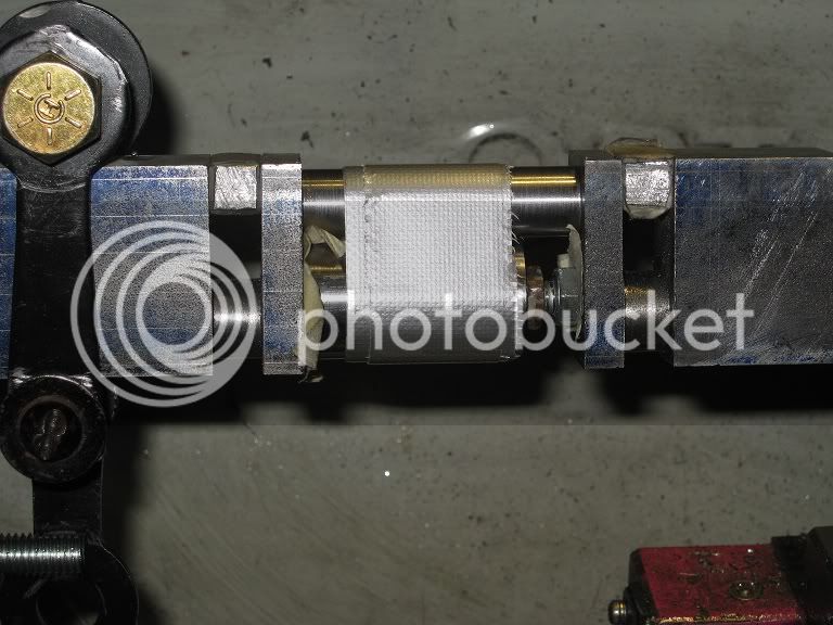
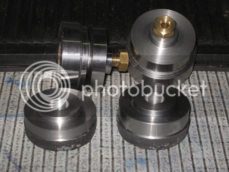
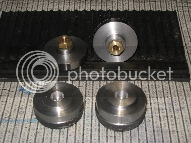
Parting off one of the new lower heads: had to get a bit creative into holding it into the chuck: no way to close the workpiece into the normal jaws, no way to part it if held into the lower step of the external jaws
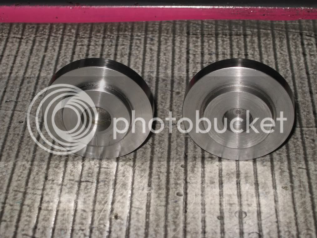
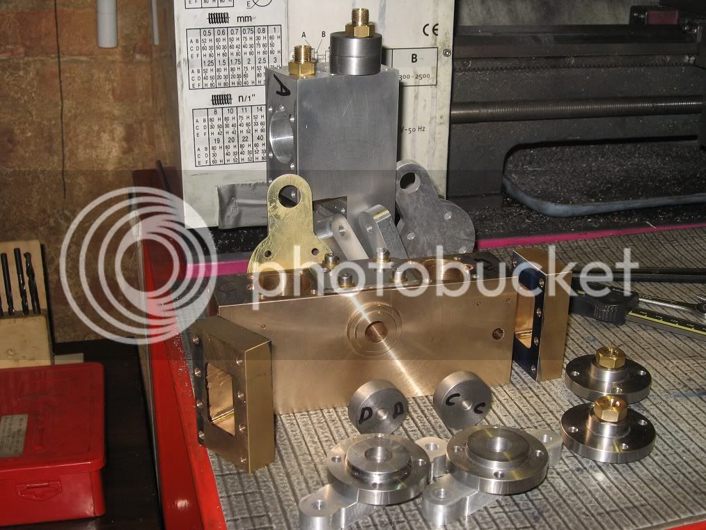
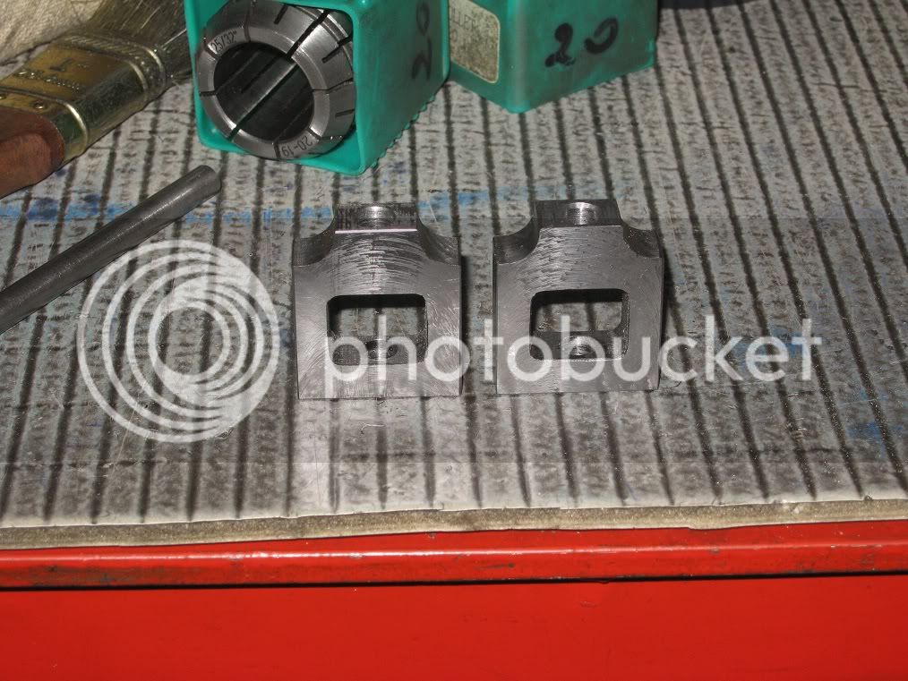
Heres the heads, before drilling the holes. (Theyre finished, now but for tapping the foot holes).
Back on the waterpipe crosshead and al. steam chests.
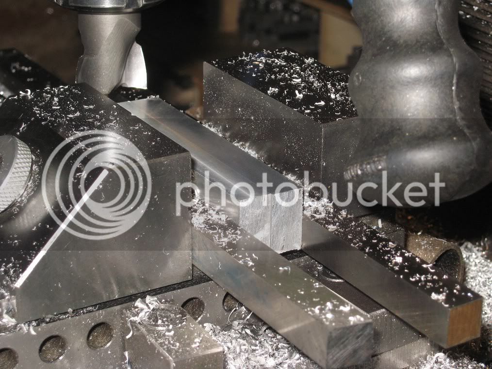
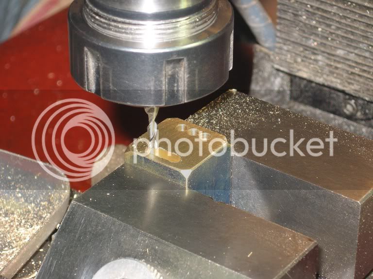
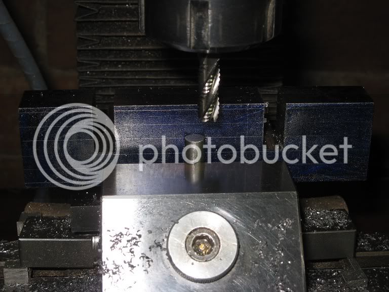
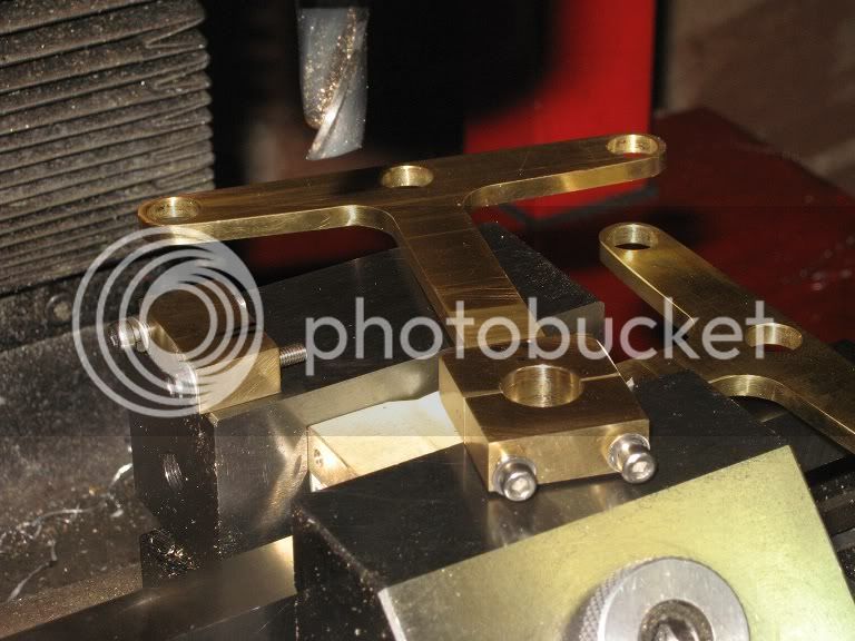
Spent too much time turning, lately: needed a little milling for a change.
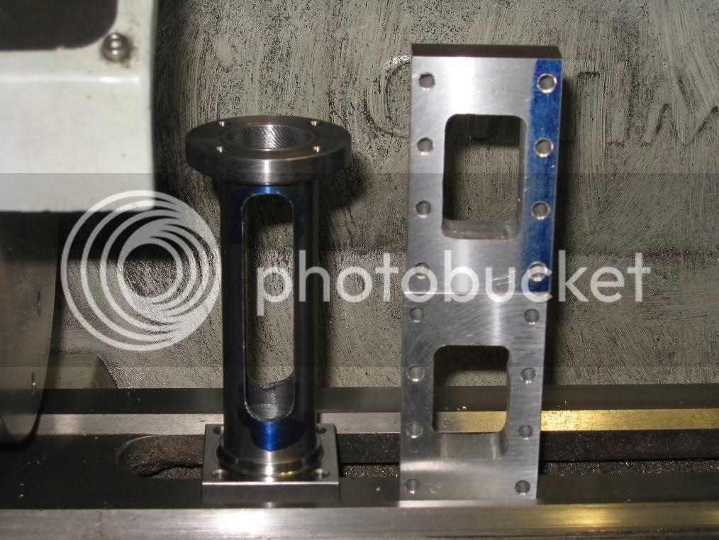
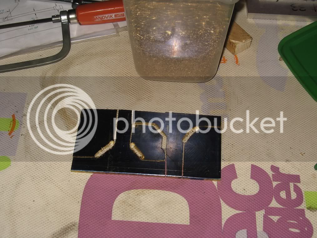
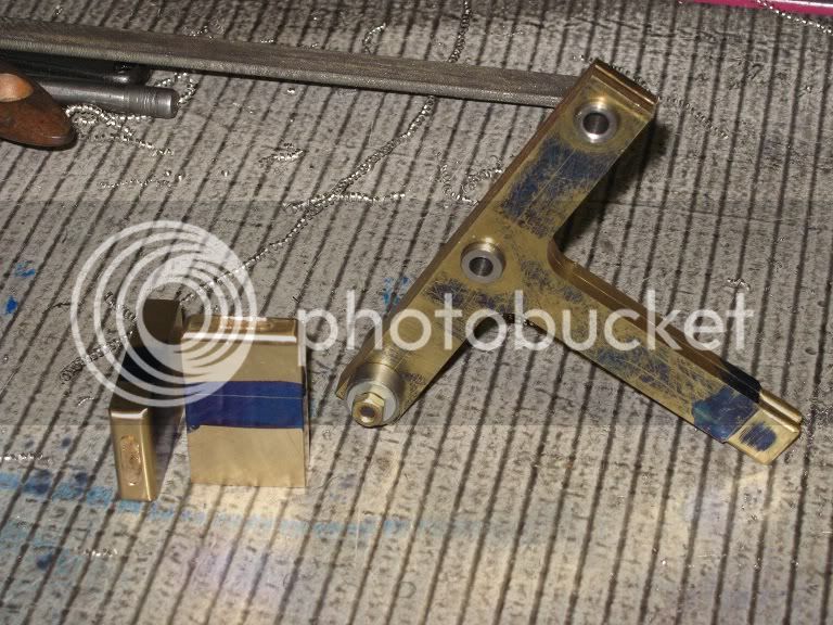
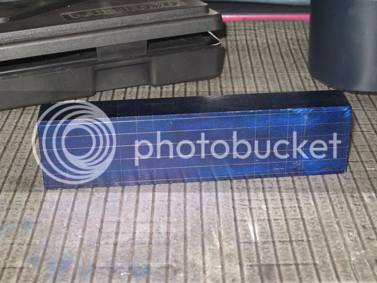
Took no pictures of the works, heres the results, yet to be deburred.
As a side note, the opening into the first steam chest came out definitely tapered. Strange! Sounds like a milling bit flex problem. I might have been feeding too heavily while milling.
(...)
The second came out as bad as the first: this al. is definitely a bad alloy!!.
(...)
When I started milling the slot into the steel, I realized there was again more than a fair share of play into the spindle: that recent session with the large flycutter (60mm, radius) more than 1mm deep cuts...
Bet I know what You will say.
Had to spend a little time into re-setting the spindle preload.
and back to the bronze cylinders block.
Gotta get that done, soon or later! (In other words, I could find no excuses to postpone this operation a little more).
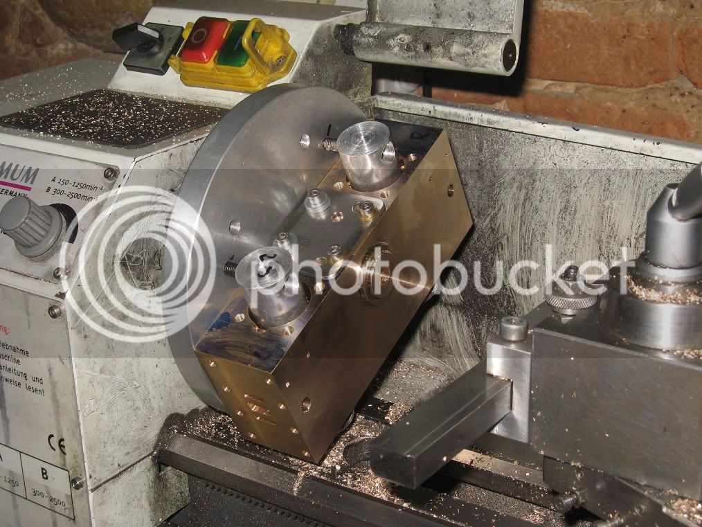
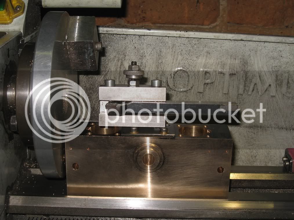
Here it is, the, still mounted on the faceplate, first side already made:
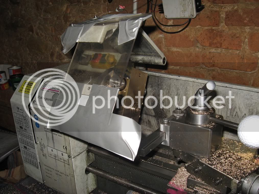
It barely swung on the lathe: about 1mm of clearance between the lower corner and the V on the lathe ways.
The tool is an insert holder, with a carbide insert made for cast-iron: had to mount it into the holder as back as I could to reach the external end of the workpiece.
Another option would have been a LH tool, turning the QCTP 90deg towards the operator.
Had to make a temporary chip shield extension, too.
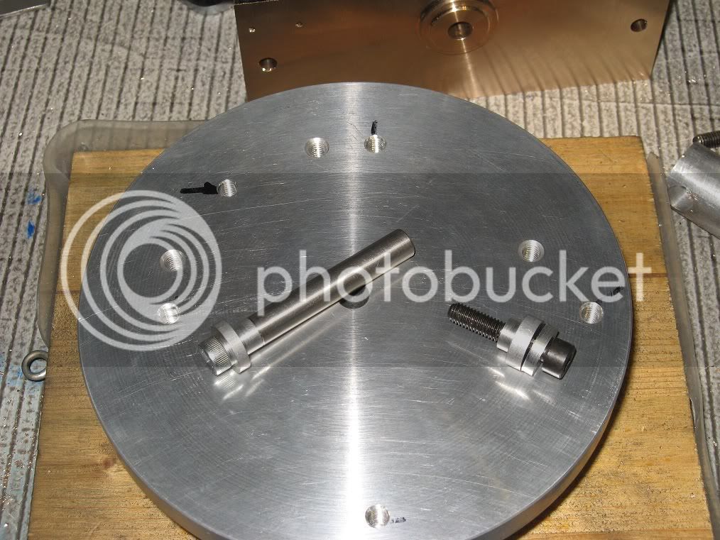
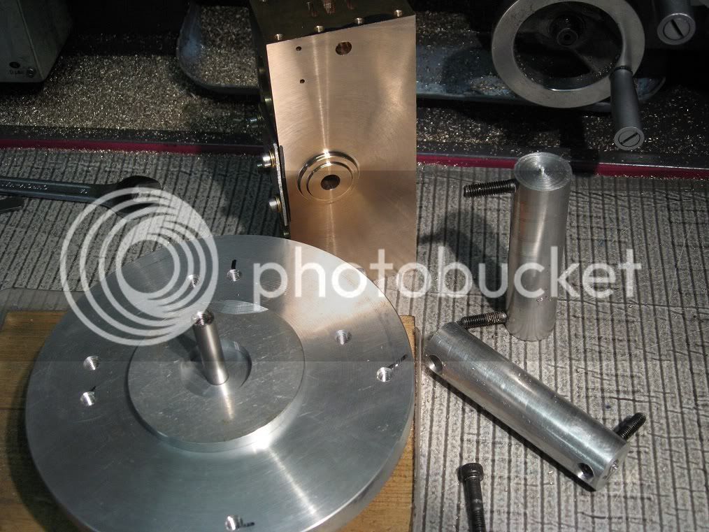
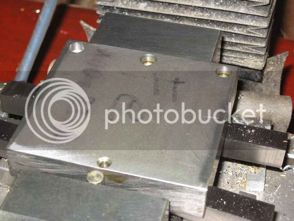
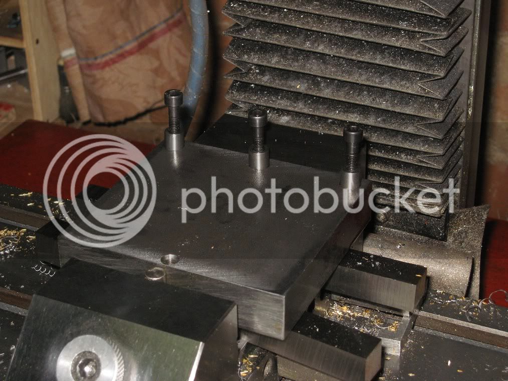
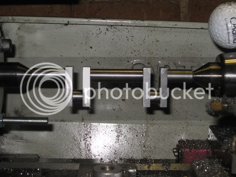
Heres how I mounted the block:
The 8mm rod fits nicely into the faceplate hole and into the (still undersized) crankshaft hole of the cylinder block: that should ensure alignment.
The two aluminium rods will go through the cylinders bores, and the aluminium disk on the faceplate will accept the already machined bearing taper
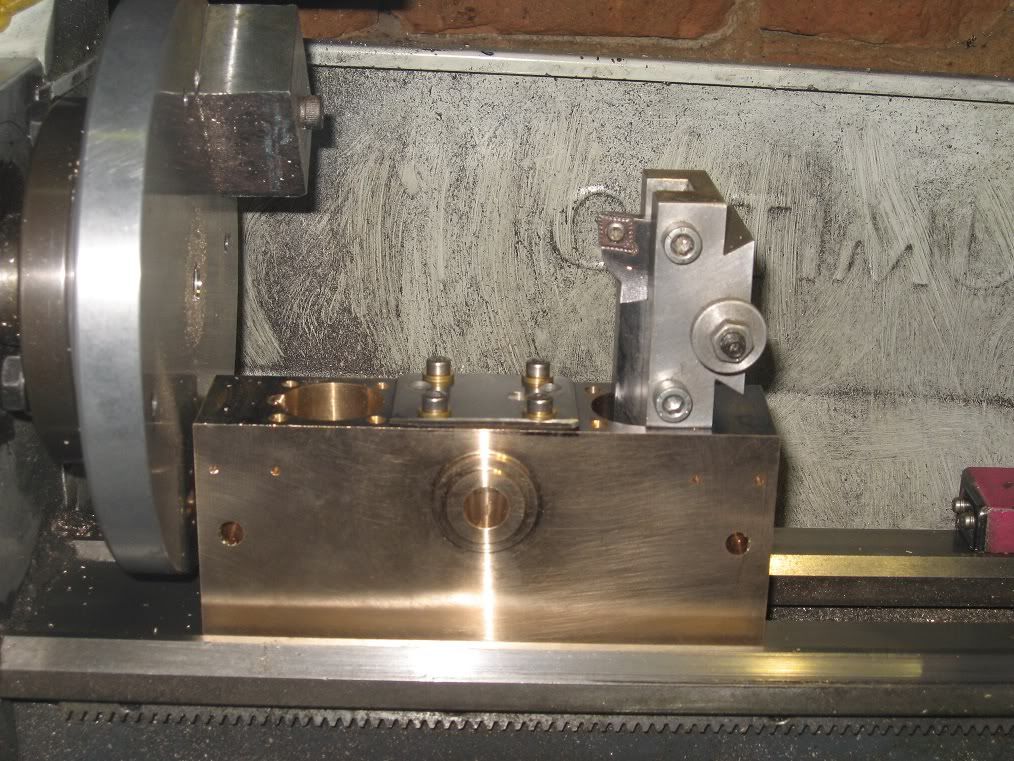
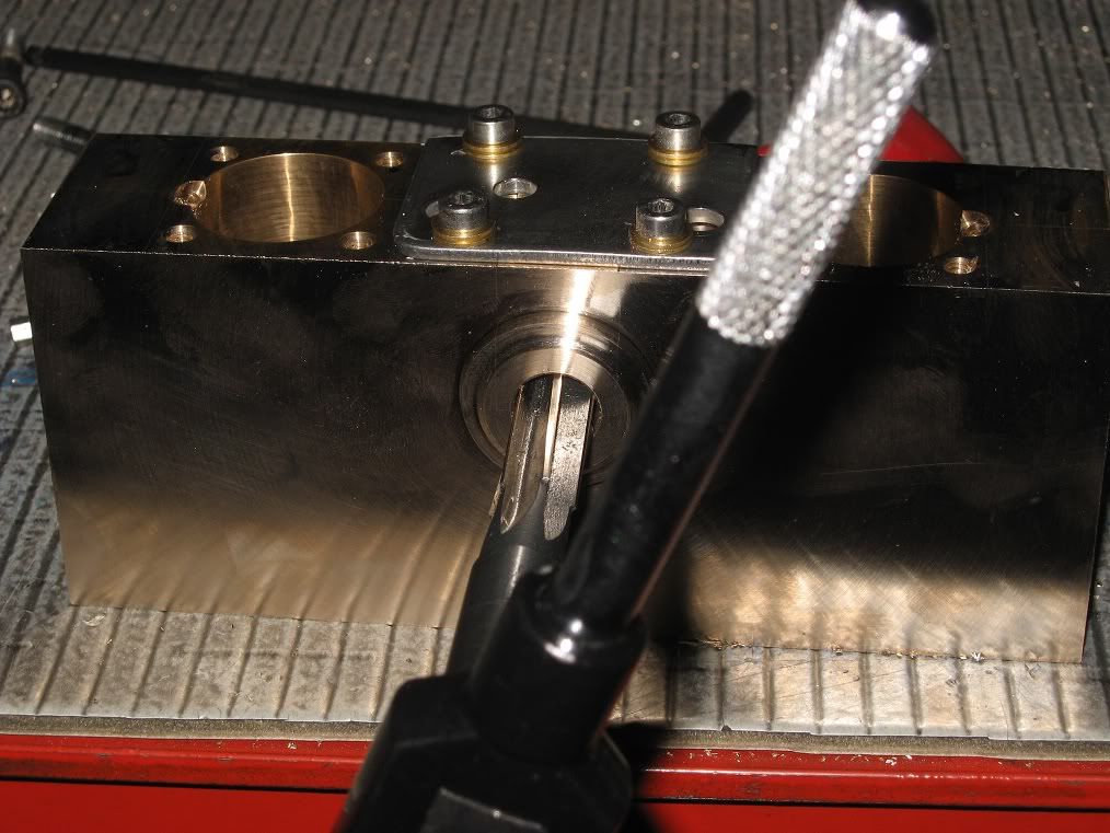
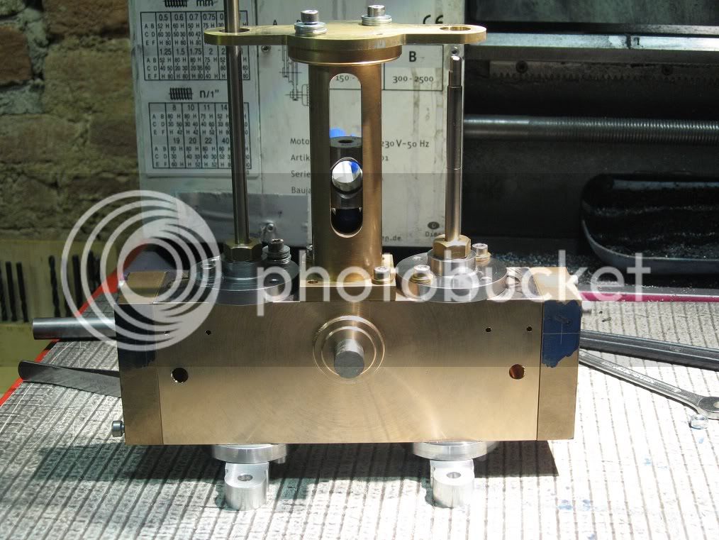
A couple of pictures of the finished block, with the crankcase bore already enlarged to 11.85mm (drilled to 10 and then bored to the final size) and the tool I had used to face it.
You have probably noticed theres a counterweight, still mounted on the on the faceplate, if not its absence in the previous pictures: definitely, a must I should have added before.
I could complete the first side without it, by turning the wp. at very low speeds, but it took soooOO long
Much more than what I spent into drilling a couple of holes, and tapping the one I had put on the faceplate.
Reaming the crankshaft bore, to the (chosen) final size of 12mm.
Marcello


