Bazmak - gearcutting

Home Model Engine Machinist Forum

Help Support Home Model Engine Machinist Forum:

This site may earn a commission from merchant affiliate links, including eBay, Amazon, and others.
How are you going with those Mod 1 cutters you bought, Bazmak?

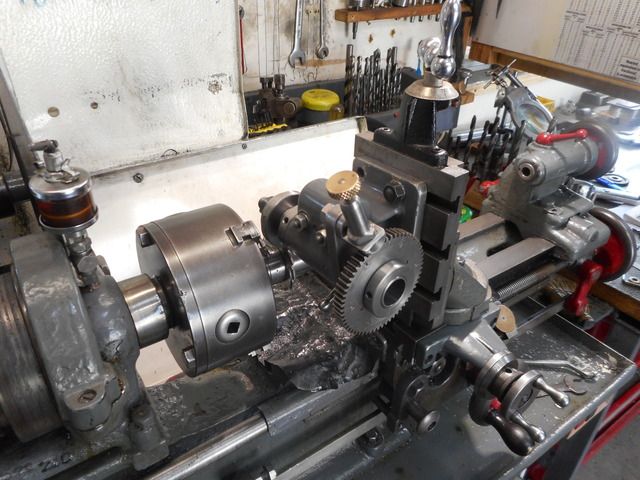
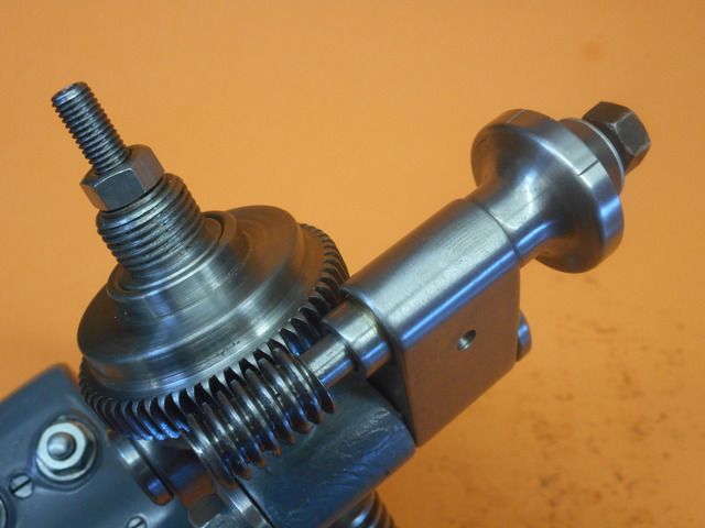
Just to throw in my two cents' worth, here's a few pics of my latest gearcutting, using a 32DP cutter from RDG tools to make the secondary worm wheel for my GH Thomas dividing head I am making from welded-together bits of scrap. I used a Myford 60T changewheel for the main gear and turned a worm to fit it. I got away from having to offset the worm at the helix angle to mesh with the straight gear by turning the thread a bit thin and angling the worm around straight.

But to cut the second, smaller wormwheel for the ultra fine adjustment on this dividing head, I ended up angling the blank at 4.2 degrees to the cutter and so the teeth are at the right angle to match the helix of the worm. Not a helical gear, but more a straight cut gear with angled teeth! And it works a treat.

Cutting the gear teeth in the lathe (1937 Drummond M-type). The vertical slide is stretched about as high as it can go. Should really have a spacer block underneath, but hey we got away with it! Used a jury rigged plunger on the main wormwheel for direct indexing.

The resulting gear, with 4.2 degree "helical" teeth
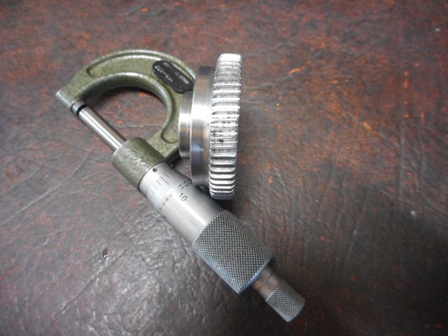

And matching worm
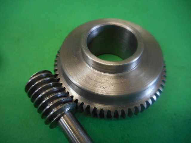

How it all fits together
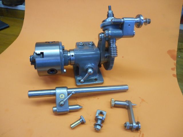

Index plates will attach to the small wormwheel on the left. A graduated micro-adjustment goes on the worm spindle on the right for dividing prime numbers etc, and making the dividing head's own indexing plates from scratch.

In the end, I was glad I spent the money on the commercial cutter. The two inch diameter steel gear, 5/16 thick would have been a long slow job with a single tooth flycutter and I don't think the vertical slide would be stout enough to take much of a cut, it was bouncing about enough under the smooth sailing of the commercial cutter.
 
Great stuff to see another GHT Versatile Dividing Head. After the roof came off( twice) during the winter storms, my division plates are really corroded and along with the Gibraltar casting and the Cleeve thing, I got 3 division plate blanks for drilling from Hemingwaykits. At least the second worm is usable. Probably I'll get away with the single hole division plate which seems OK.

So I look forward to your next gripping instalment out of the George Thomas stable

Norman
 
Great input,good to see someone else flying by the seat of their pants
I haven't used my involute cutters,will save them for when I need to make gears to be used
 
I missed the bit on first reading of 'thinning' the worm( To overcome the helical messing problem, folks)

Then I suddenly recalled that the late Martin Cleeve wrote it up in Engineering in Miniature. If my aged memory is working today, it was on the Alan Timmins dividing head which was serialised in an early EIM. The castings and whatever were sold by Blackgates Engineering. Hopper, I haven't the articles now- sorry.

A lot easier than the GHT affair!

Hint-- the Stent t&C from Blackgates Engineering is quite possible without castings. We were discussing mine which another old geyser made- by welding .Quite a toy- which is easier than the Quorn but is really a diminutive Clarkson.

N
 
Norman, yes I think it was in Cleeve's book on screwcutting that he mentioned thinning down the Acme thread so the worm could mesh straight on with a straight cut gear. The thing I like about GHT's design, fiddly as it is, is the ability to make its own index plates by using the micro-adjustment attachment. I just saw a picture of the Timmins design for the first time the other day, it looks quite rugged and simple. Also uses a Myford change gear for the worm wheel.
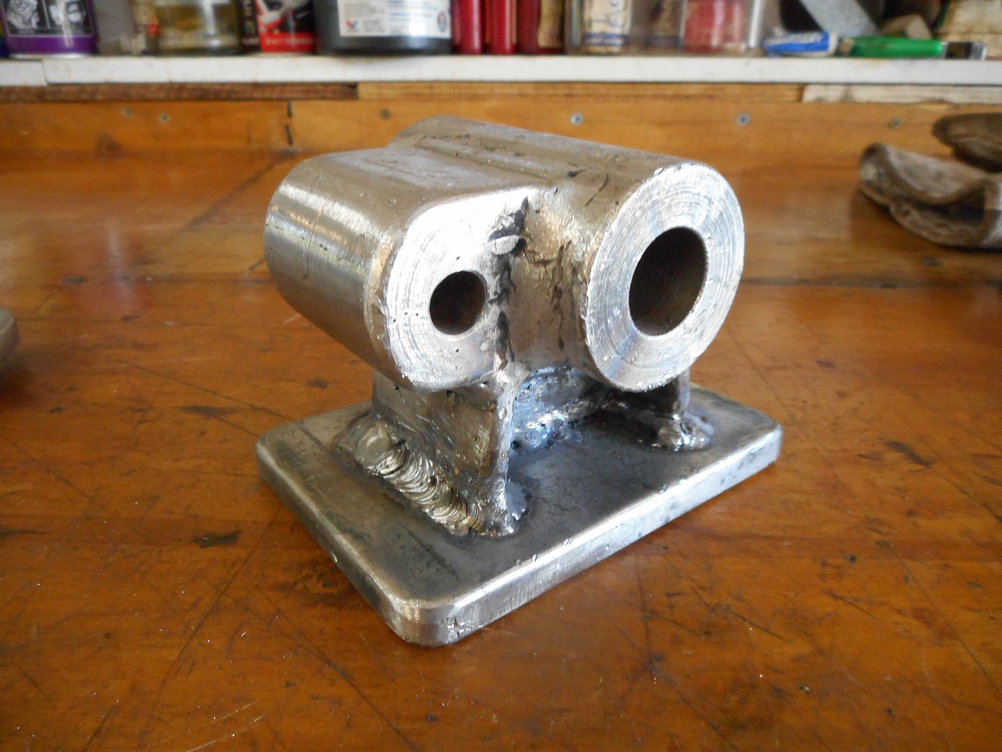
I have thought about a fabricated Stent but shed time is limited these days so it will have to wait. FWIW, here's a pic of the fabricated GHT body under construction. Yes, talk about flying by the seat of the pants!


Now, I never claimed to be a welder!

After a good heat soaking to cherry red and a night in the lime bucket to stress relieve and anneal:


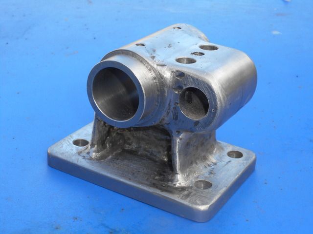
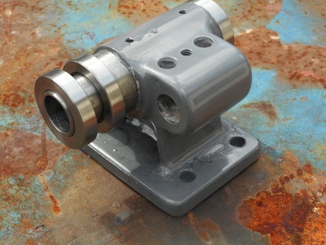
Nothing a little bit of die grinding, body filler and paint won't fix though:

LOL, I never claimed to be a painter either! You can see the result of painting over putty in 90 per cent tropical humidity around the base of the legs there. We live and learn!
 
Hopper, I continue to be amazed at your approach to making this dividing head. Of course, for other readers, Thomas published I the back of his book 'WorkshopTechniques' and earlier in 'Dividing and Graduating' the plans for the castings - should one be stuck on a desert island or something. I'm certainly more than impressed.

As I remarked earlier-somewhere, I had his fabricated Universal Pillar Tool and now have the Mark2 machine. Again, I suggested that the 'legs' might well be from a scrap set of full size conrods. Somewhere in my heap of things, there are the drawings of an automatic thing to graduate divisions. I'll dig them out and e-mail them to add to your collection.

I 'made' Hong Kong' and then onto 'Fiji' in June and I wonder if I can make another trip- further South.

Meantime, Best wishes

Norman
 
Thanks Norman. Model engineers always welcome on this rather large desert island. Con rods for the pillar tool - brilliant idea. I have a motorbike flywheel truing stand made from two conrods bolted to a bit of steel channel. Been truing Harley crankshafts on it for decades without a problem.
I'm still having many enjoyable hours reading through Cleeve et al in the treasure trove.

I have some drawings from Harold Hall's book on Dividing for a graduating tool with a ratchet mechanism to automatically vary the stroke length on every fifth and tenth stroke for making graduated handwheels. I am about ready to make the graduated thimble for the GHT micro-adjustment and thought about making the HH graduting tool, but once again in danger of completely disappearing down the rabbit hole of making tools to make tools to make tools recurring. So I will probably bodge something out of a toolmaker's clamp and a bit of allthread rod, or something. That's tomorrow's project so I'll worry about it then.

Bazmak, sorry about the thread hijack mate. I guess it's all gearcutting related so maybe will be helpful to someone?
 
I guess that I am also guilty of 'High Jacking' your thread but frankly, you have opened up a very important topic.
I'm sure that many will appreciate it in addition to me

Regards

Norman
 
This thread has opened a new line of thought for me with a sleepless night
(design time).Can I make and fit a worm/wheel to my index head for
more accurate dividing.
Can I use a std mod1 spur gear and offset the worm to the helix angle
Can I hinge the worm from the far bearing to allow the worm to disengage
when using the plates and also allow adjustment to reduce eliminate backlash
Still thinking,keep this thread open
 
Bazmak, you certainly could do that. Easiest way is to do what I did and cut yourself a 60T gear using your module 1 cutters, but set the blank at the helix angle so the teeth are a the right angle to match the worm helix. Or you can do what I did on the main gear and use a straight cut Myford (or any other) change gear and when you turn the worm thread, a standard Acme profile, cut it a bit deep and wider than normal. This allows you to twist the worm to the straight position but still mesh properly with no backlash.

The tricky bit is working out the pitch to turn the worm at so it matches the circumfrential pitch of the gear, THEN, working out the change gears to cut the oddball resulting pitch (8.37tpi or some crazy thing like that). Martin Cleeve's book on Screwcutting in the Lathe covers it a bit, but not sure if he includes metric for module 1. He does include DP20 etc. And does include the outline of how to calculate it yourself. (Makes my head hurt though.)
Also GH Thomas's books include details on doing it for the two gears, DP20 and DP32 on his dividing head.

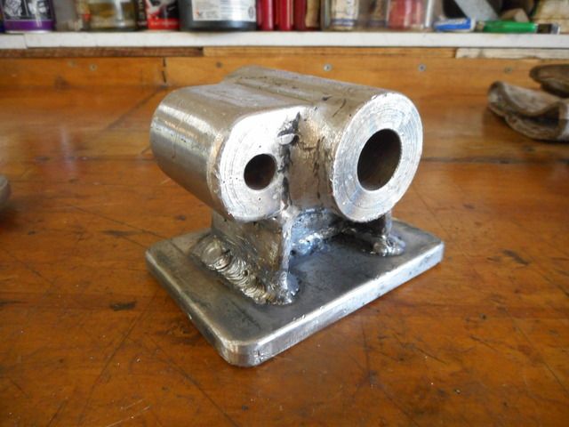
I have some pics somewhere of the fabrication process for the body, I will dig them out when I have time later and post them. Basically it was two pieces of 1-5/8 round bar welded together to make the main body to hold the spindle and the tailstock bar. I machined a curved scallop out of one side of one piece of the bar so it matched the OD of the other piece and then welded them together and milled a flat on top of the second piece. Then the cross piece for the locking mechanism was turned from a piece of 3/4" bar, again with a scallop machined out of it to fit up to the main piece. Then the base and the legs were cut from flat plate and welded together. Clear as mud? Will post the pics later today.
 
thanks for your post Hopper,i have made a start.I don't have a spare suitable
mod1 changegear the tooth pitch would be 3.142mm and then I would have to cut an acme thread to suit and offset the worm by the helix angle
A far simpler way I have decided is to cut the gear using an M20 tap as a hob
and an M20 bolt as a worm.2 screws remove the dividing plt and detent assy
easily replaced with the worm and wheel.More room and less complicated than
trying to fit both.I am making a 120t gear which will give me 3o with a full turn of the worm,from cast iron. Will posted
 
Good idea. I guess with a 120T gear you could use a standard chart for a 60T as far as number of turns plus holes and then double the result.
 
OK, the fabrication process.
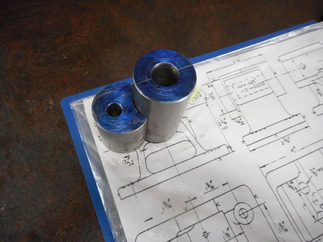
Showing the two main pieces, machined from 1-5/8 round bar. Holes bored to rough undersize at this stage. I printed out GHT's drawings at full size and used them to make templates adn mark out materials to correct size.


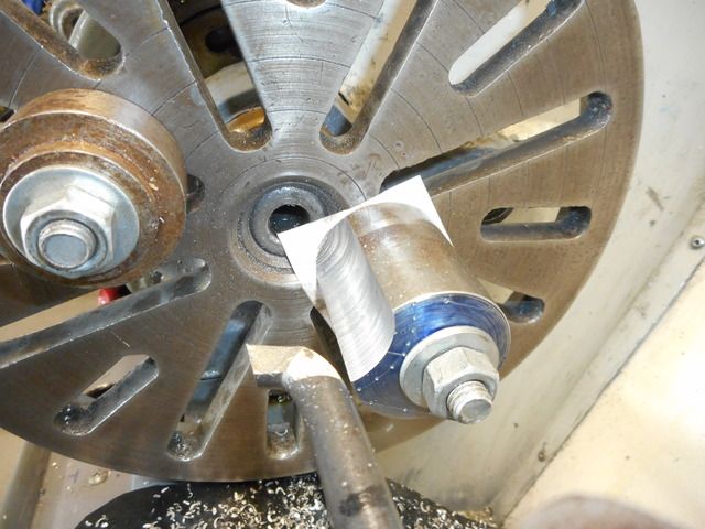
The scallop in the one piece of 1-5/8 bar was machined like this: offset on faceplate and "bored" to 1-5/8 diameter to match the other bar OD


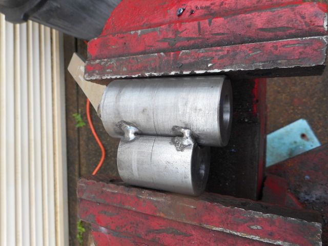
This allowed the two pieces to be very easily aligned and welded together in the vice. You could just as easily make the second piece from flat plate and machine a flat on the main piece for it to mate to, but I had no access to flat plate that thick so used what I had, the large round bar.


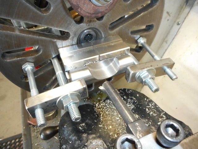
Next, the barrel for the locking mechanism was similarly machined from 1" or 3/4" round bar, scalloped to fit to the main barrel so it can later be drilled and reamed for the locking mechanism to go inside it.


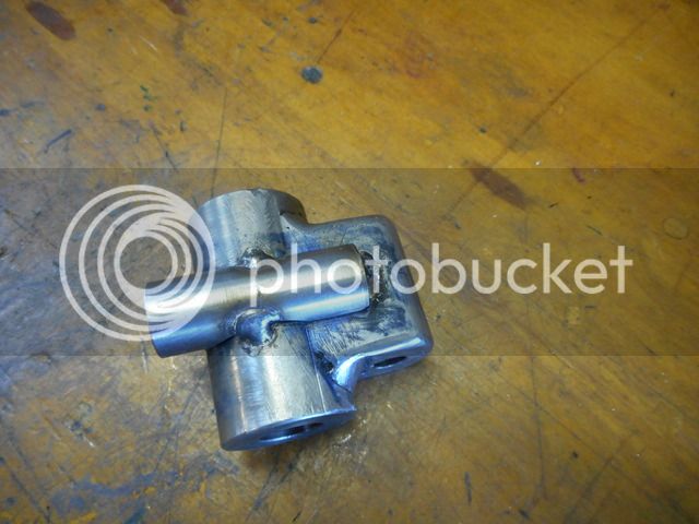
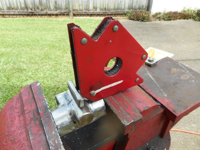
Here it is tacked into position

You can see in the above pic that I milled the top and bottom of the second piece of 1-5/8 bar flat, mostly just so it duplicated the look of GHT's casting. Final welding on thos surfaces was done after the milling. (The weld on the ends held the piece while milling was done.)

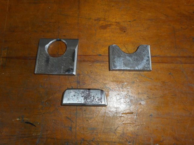
Next, some bits of scrap 5/16 plate were marked up, hole bored to match the above piece it will mate to. The end piece was cut off and discarded after boring to size. The ends of the two vertical support plates were bevelled to mate up to the main 1-5/8 barrel. The small piece is the "web" that runs between the two uprights, just like the web in the casting.


Web welded in place


Legs added


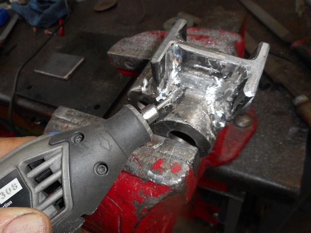
Welds cleaned up while access is clear with no base plate in place.


Final welding to the base.


The resulting "casting" was then machined as per GH Thomas's instructions in his book "Workshop Techniques". I can tell you from experience that you ignore his advice at your own peril!

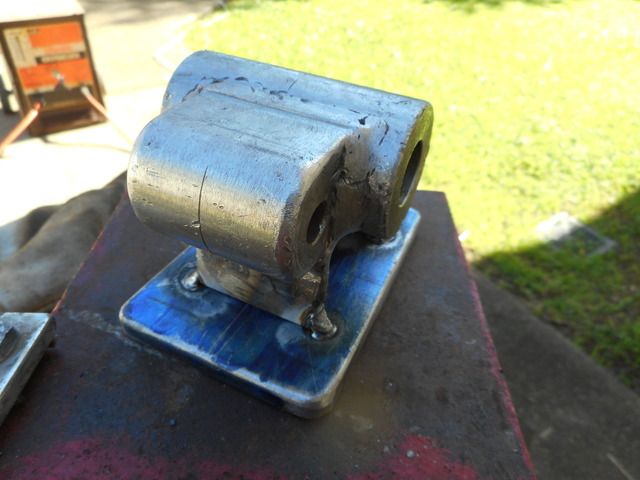
Base plate tacked before welding


The whole thing welded to the 3/8" base plate
 
Oops, last pic is out of sequence but I missed the time limit to edit post. You can see my $50 garage sale welder in the background. Came with 5kg of rods I am still using!

Also, meant to mention the rough-bored undersize holes up the middle of the two main pieces are essential to use for alignment when doing the machining. The original casting comes with the two holes cored. I bored the main hole to a nice fit on 3/4" BMS bar which was inserted though the hole and used to set the "casting" straight on the boring table of my lathe for machining.
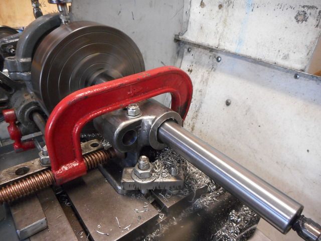
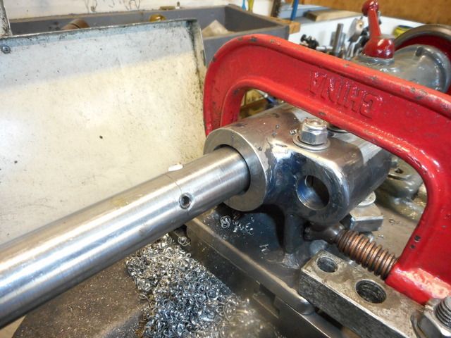
Holes were then bored with a between centres boring bar so they are perfectly at centreheight for my lathe.
 
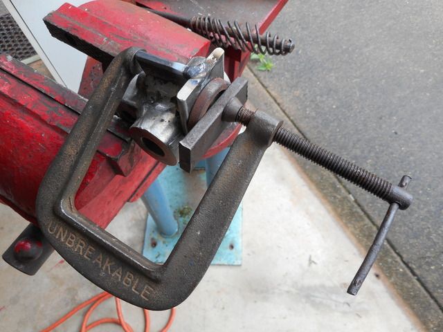
Durn, missed the timeframe to edit post again. How weird is this site? Anyhow here is the pic meant to go with previous post showing how the holes were machined using between centres boring bar. The G clamp is holding the brass locking plugs in place while they are being machined in place to perfectly match the bore of the main barrel.
 
Back to Thomas again? I did my Quorn with mine as well.

Perhaps it should be mentioned that regardless of the wear in the old lathe, an in line boring bar will bore DEAD parallel. Not necessarily the CORRECT DIAMETER however.

Confession- I angled the tool bit at 45 degrees and it should have been 40. If it had been 40 I could have used the 40 tpi thread to read in thous. Silly me!:confused:

Regards

Norman
 
Norman, I did not even fit adjustment to the boring bar. Just drilled one hole in it at 45 degrees for the HSS tool bit to go through and another for a clamping grub screw. Used a micrometer over the tool point and the bar to measure size. Bored the hole first, nice and true and smooth but ended up some few thou bigger than teh nominal size. No problem. Just turrned the spindle to fit the hole.
 
Hopper
I enjoyed the approach- which obviously works:thumbup:

Moving off a little( Hope Barry will accept) I noticed your 3 jaw etc and would add that one of mine is drilled around the periphery to accept a detent. True, it's old fashioned and I didn't do it, but it is very useful on the lathe and the universal dividing head.

I've been playing with a little digital angle thing- which is a good substitute for lots of angle things.
Thinks, I'll spend the Children's inheritance on a 6" 180grit CBN wheel:wall:

Regards to All

N


-----------------------------------------------------------------------------------------------------------------------

Apparently I have been blocked from other posts.

The reasons are not even 'vague'

Thank you for putting up with me in the past.

All that I can say? Well- politely

Norman
 
Norman, I've made a little angle bracket to mount the plunger off the GHT dividing head on the change gear quadrant and engage with a gear on that end of the lathe spindle, so no need for drilling the chuck backplate. Will be using it to make the graduated collar for the micro adjustment so will keep you posted.
 
Back
Top