- Joined
- Dec 2, 2008
- Messages
- 971
- Reaction score
- 9
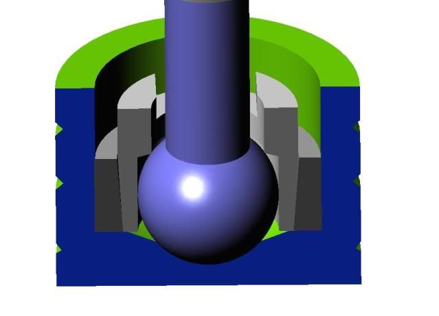
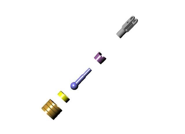
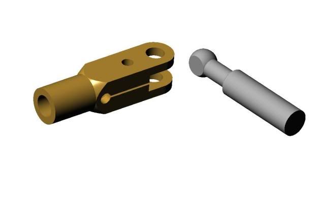
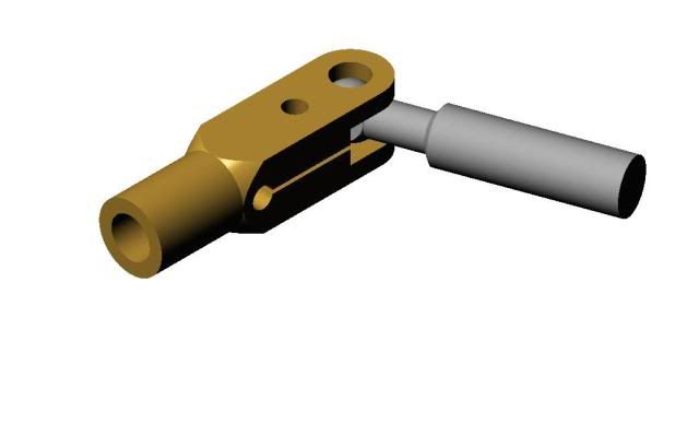
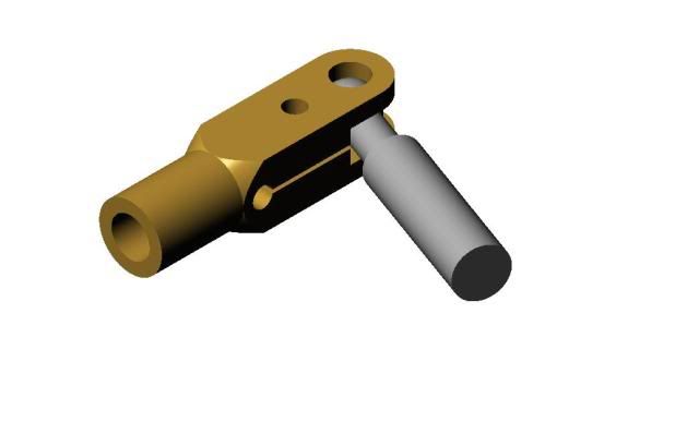
How to make a ball joint. I needed to make ball joints for the pistons in my 6 cylinder wobble plate engine and I decided to make this a separate topic since there are other applications where this might be used. In a wobble plate engine, the piston rod cannot use a regular wrist pin because it must offset in all planes, not very much, a matter of a few degrees, but the action must be free and with no end play. To be really useful, the design should allow for wear adjustment.
The engine thread is here: http://www.homemodelenginemachinist.com/index.php?topic=6707.msg92205#msg92205
The first step is to produce a ball on the end of the piston rod. The piston diameter is .625" so decided on a ball diameter just less than half that. I started with a length of 3/8" CRS from the hardware store. I chucked it up in the lathe with about 2" extended to keep my hands at a distance from the chuck.
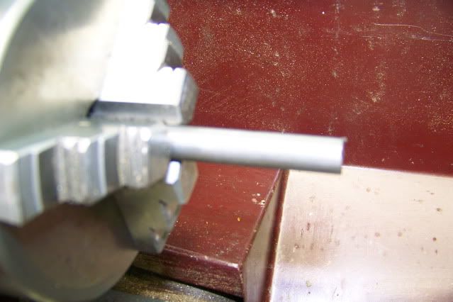
I turned this down to .300" for a length of about one inch.
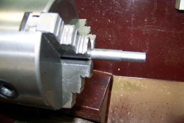
Moving in from the end of the rod, I reduced the diameter to .1875" leaving a lump on the end from which to fashion a ball.
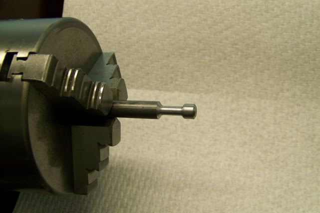
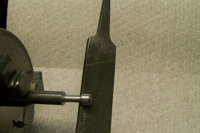
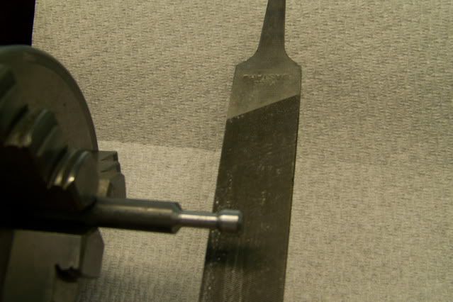
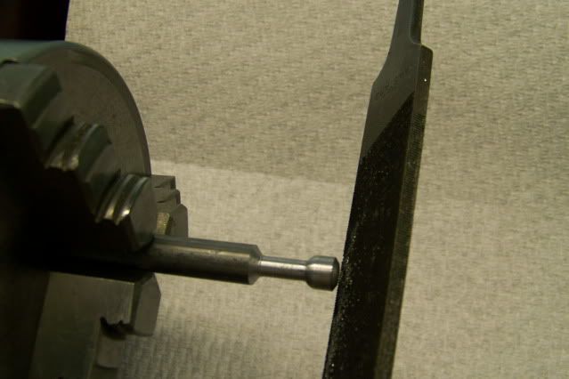
If I had a ball turner, I would have used it but I don't so I used a mill on a stick (a technical term for a file that I picked up on this forum). I use the file to shape the ball freehand. In order to see the ball as it takes shape, I use the file under the stock with the tang facing to the rear. I used to be a fairly competent wood turner, giving exhibitions a state and county fairs throughout the east coast. I could turn a nearly perfect 2" ball on a piece of sugar pine in less than 1 second with two passes of the scew chisel, one to the right and one to the left, so I guess I still have a pretty good eye but I think anyone could do as well with just a little practice. It took about 30 seconds with the file to produce the rough ball on the end of the rod.
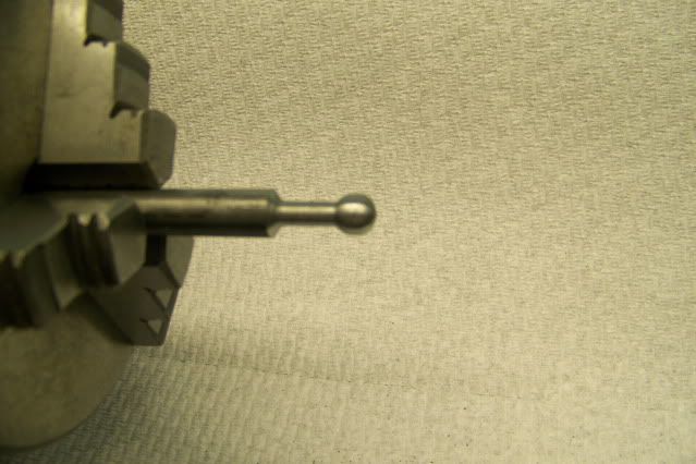
The rough ball was then ground to precise sphere and polished in the lathe. I made a special grinding tool from another piece of the steel rod by facing the end and drilling 9/32" diameter hole .25" deep and chamfering the edge. The hole was then charged with valve grinding compound and chucked in my electric drill.
With the lathe running at about 800 RPM and the drill running about 1200 RPM, the charged end of the grinding tool is applied to the rotating ball with moderate pressure and moved from side to side, keeping the ball in the charged depression.
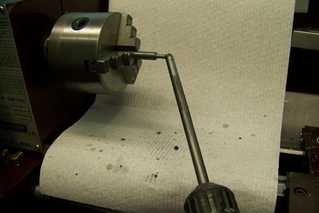
For the first few seconds, it will look like the grinding to is only making contact at two places as shiny rings appear on the ball. These are the high spots. As the high spots are ground down, the shiny rings get wider. Keep moving the tool back and forth. you can go from almost in line with lathe axis to the right and then to the left till the grinding tool contacts the rod. Within about a minute, certainly less than two, the shiny lines have widened to the point that they merge and the ball is a sphere. Wipe the ball clean with a little turpentine and clean out the charged end of the tool. Take the tool out of the drill and with the lathe turning take a strip of 1200 wet/dry paper an lay it over the ball and press the tool to the ball trapping the paper between the tool and and the ball. Move it side to side as you did while grinding and stop when you are satisfied with the polished ball. Twenty or thirty seconds.
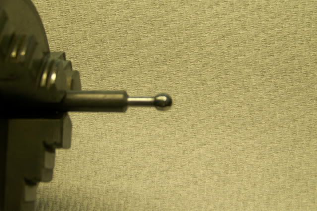
Here is the finished results. Five minutes or less.
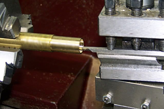
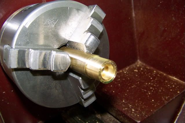
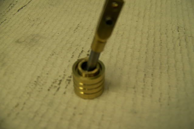
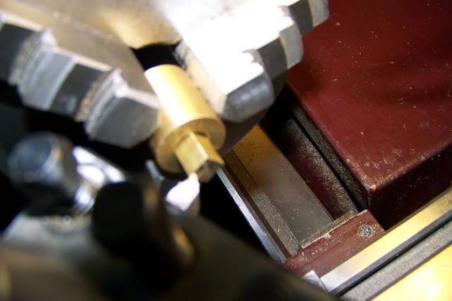
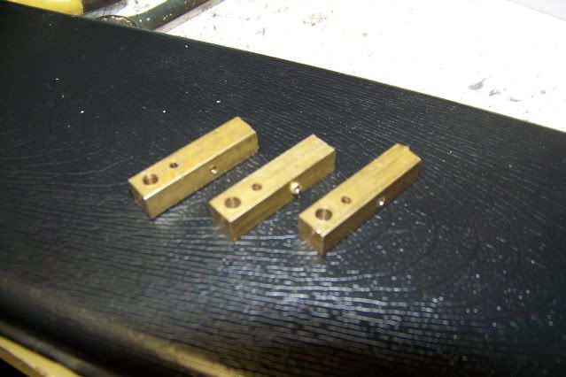
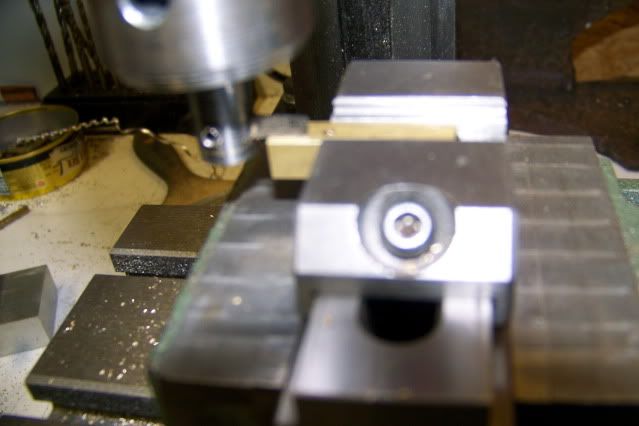
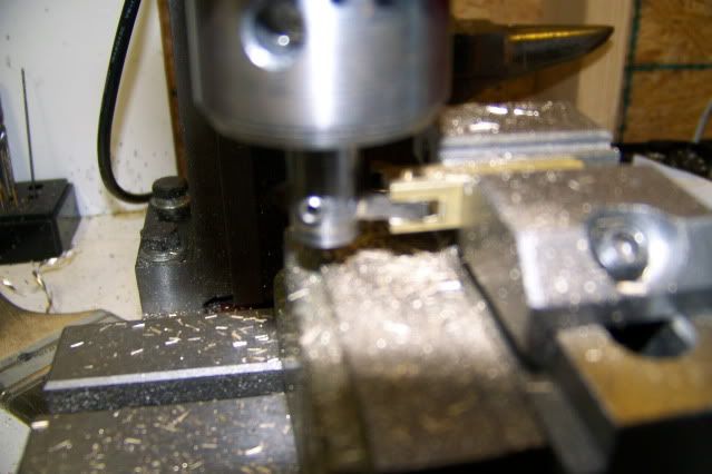
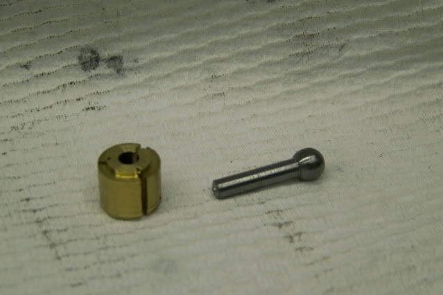
Now turn the 1/8" part of the rod to finished length and part it off. The piece of brass in the pic is a fixture to let me work the other end of the part. It is sized to allow 5 more pieces to be finished to the same length.
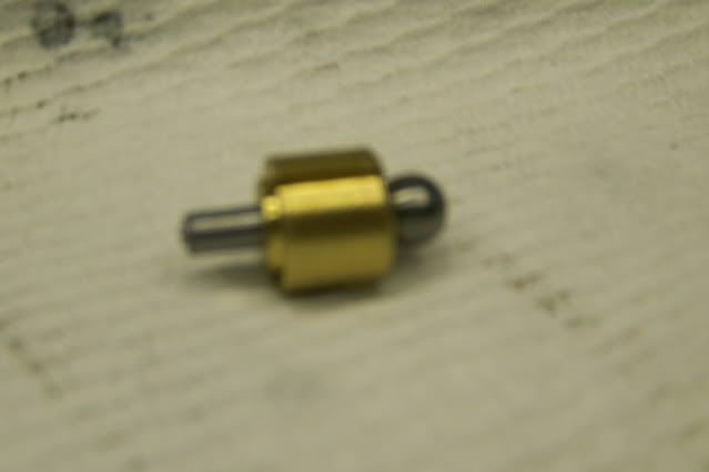
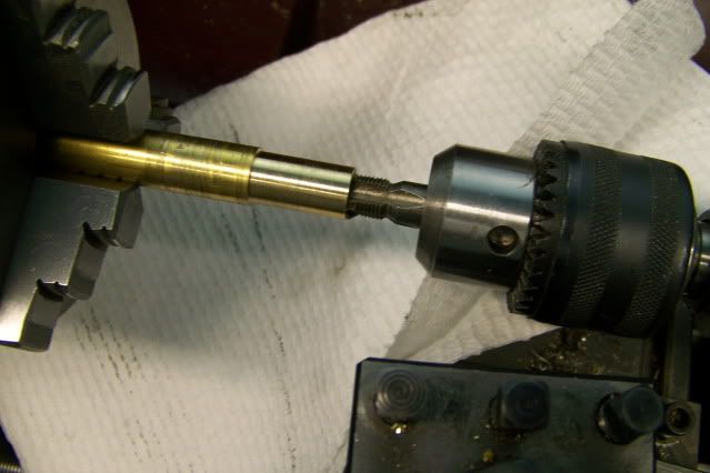
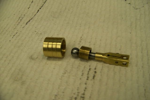
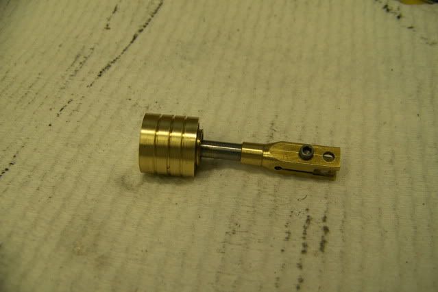
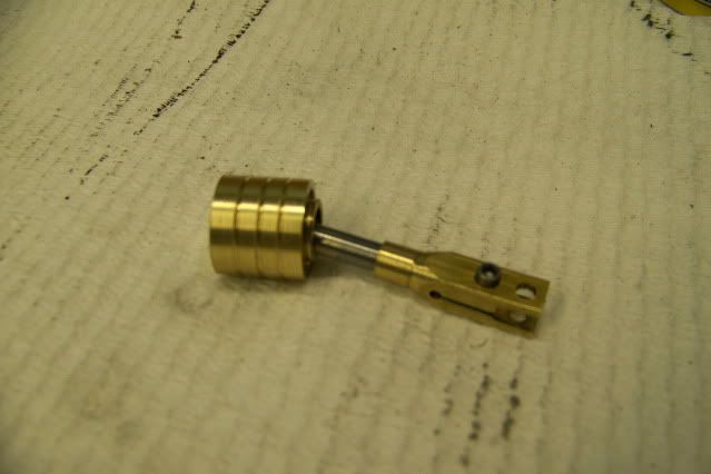
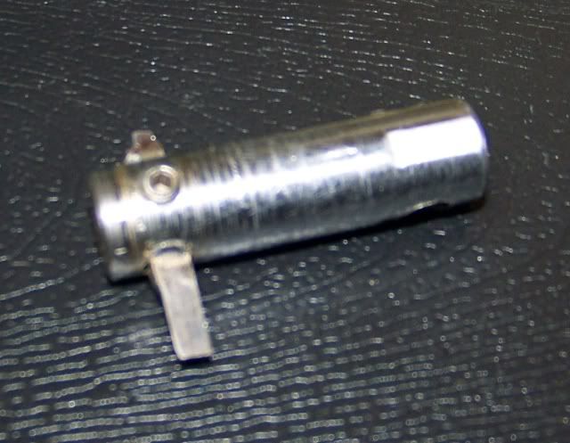
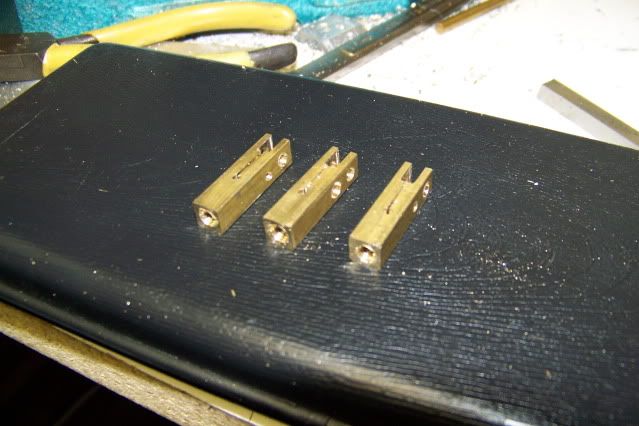
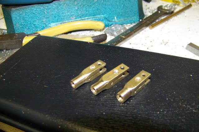
I seem to have lost a picture here but the next step is to thread the exposed end of the rod for #8-32. The next picture shows the clamp end of the rod screwed onto the threaded part and the lined up with its sisters.
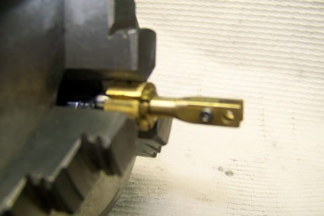
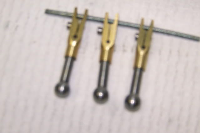
My appologies for the photo quality. Not one of my strong suits. Difficult to get focused.
It is now getting late so I will continue tomorrow with the socket and retainer. That's a little more complicated.
Jerry
The engine thread is here: http://www.homemodelenginemachinist.com/index.php?topic=6707.msg92205#msg92205
The first step is to produce a ball on the end of the piston rod. The piston diameter is .625" so decided on a ball diameter just less than half that. I started with a length of 3/8" CRS from the hardware store. I chucked it up in the lathe with about 2" extended to keep my hands at a distance from the chuck.

I turned this down to .300" for a length of about one inch.

Moving in from the end of the rod, I reduced the diameter to .1875" leaving a lump on the end from which to fashion a ball.

If I had a ball turner, I would have used it but I don't so I used a mill on a stick (a technical term for a file that I picked up on this forum). I use the file to shape the ball freehand. In order to see the ball as it takes shape, I use the file under the stock with the tang facing to the rear. I used to be a fairly competent wood turner, giving exhibitions a state and county fairs throughout the east coast. I could turn a nearly perfect 2" ball on a piece of sugar pine in less than 1 second with two passes of the scew chisel, one to the right and one to the left, so I guess I still have a pretty good eye but I think anyone could do as well with just a little practice. It took about 30 seconds with the file to produce the rough ball on the end of the rod.


The rough ball was then ground to precise sphere and polished in the lathe. I made a special grinding tool from another piece of the steel rod by facing the end and drilling 9/32" diameter hole .25" deep and chamfering the edge. The hole was then charged with valve grinding compound and chucked in my electric drill.
With the lathe running at about 800 RPM and the drill running about 1200 RPM, the charged end of the grinding tool is applied to the rotating ball with moderate pressure and moved from side to side, keeping the ball in the charged depression.

For the first few seconds, it will look like the grinding to is only making contact at two places as shiny rings appear on the ball. These are the high spots. As the high spots are ground down, the shiny rings get wider. Keep moving the tool back and forth. you can go from almost in line with lathe axis to the right and then to the left till the grinding tool contacts the rod. Within about a minute, certainly less than two, the shiny lines have widened to the point that they merge and the ball is a sphere. Wipe the ball clean with a little turpentine and clean out the charged end of the tool. Take the tool out of the drill and with the lathe turning take a strip of 1200 wet/dry paper an lay it over the ball and press the tool to the ball trapping the paper between the tool and and the ball. Move it side to side as you did while grinding and stop when you are satisfied with the polished ball. Twenty or thirty seconds.
Here is the finished results. Five minutes or less.

Now turn the 1/8" part of the rod to finished length and part it off. The piece of brass in the pic is a fixture to let me work the other end of the part. It is sized to allow 5 more pieces to be finished to the same length.


I seem to have lost a picture here but the next step is to thread the exposed end of the rod for #8-32. The next picture shows the clamp end of the rod screwed onto the threaded part and the lined up with its sisters.


My appologies for the photo quality. Not one of my strong suits. Difficult to get focused.
It is now getting late so I will continue tomorrow with the socket and retainer. That's a little more complicated.
Jerry


