Back to Steam

Home Model Engine Machinist Forum

Help Support Home Model Engine Machinist Forum:

This site may earn a commission from merchant affiliate links, including eBay, Amazon, and others.
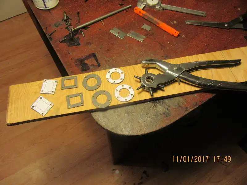
Here we have the ultimate in "low tech" gasketry. Print the parts the gaskets are going onto at 1:1 scale, cut them out and use a glue stick to stick them onto a piece of .030" general purpose gasket from the automotive supplier in town. When the glue is dry I use scissors to cut the outer profiles, an exacto knife for the inner surfaces, and a leather punch for all the bolt holes.
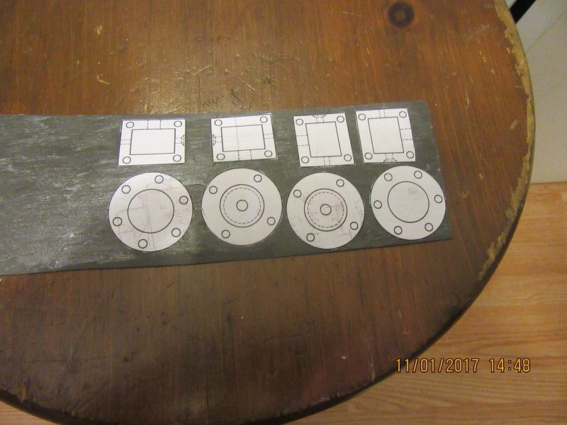
zHVIpg.jpg
 
Rather than using paper gaskets Brian,what other options are there for
steam loco gaskets.Any/best form of liquid gasget goo that does not
set too hard
 
And, if you didn't know what a leather punch looks like--this is it. The handiest gasket hole maker you could ever think of. The engine is all reassembled now, complete with gaskets but two of the control links I made this afternoon appear to be to short on one end. Will correct that tomorrow.
4dbgnj.jpg
 
Rather than using paper gaskets Brian,what other options are there for
steam loco gaskets.Any/best form of liquid gasget goo that does not
set too hard
I don't use "gasket in a tube" because you can't control it---Soon as you tighten the bolts the damned stuff squishes out all over the place, plugging air passages and buggering up the works. Apparently there are very thin Teflon sheets you can buy that make excellent gaskets, but I have never used them.
 
Thanks for your input Brian. You mentioned 30 thou matl but that will
cock up some dims.Ie if i use it between my cylinder it will alter the pisto/valve centres by 30 thou. Seems a lot. The model i am making was drawn and described in 1947 and very old fashion in details and tooling etc
Paper gaskets are mentioned but modern matls were not available then
I understand brown paper /oiled was an old fashion way.Just hoping maybe
others will read this thread and add their penneth.Keep up the good work
Keith Appleton, on one of his models, used plain old brown wrapping paper, no special treatment.
I suppose the seal depends on how good the mating surfaces are
 
I just used greaseproof/baking paper stolen from the kitchen drawer.:thumbup: for a head gasket on lapped head and barrel.
The other option I thought of trying is the heatproof sheets used for Tee shirt printing.
 
Keith Appleton, on one of his models, used plain old brown wrapping paper, no special treatment.
I suppose the seal depends on how good the mating surfaces are

Add me to the list of people that uses brown paper bags. That's all I used in several of my engines.

Only thing is that, just before installation, I coat them in light oil (3-in-one, sewing machine oil, something like that)

My Stuart Turner #1 is something like 20 years old, and the gaskets still seem to be working fine.
 
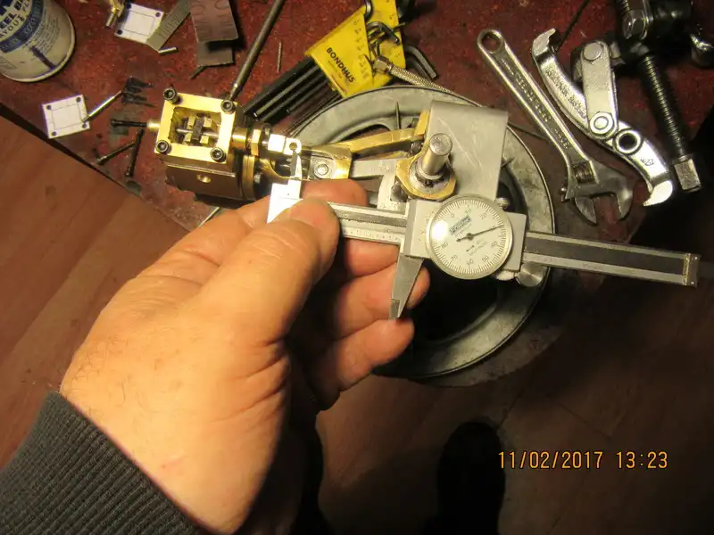
Yesterday, I made up all of the 1/8" threaded rods that transmit motion from the eccentric to the slide valve. On assembly, it became clear that I had made the rod attached to the eccentric strap too short. So, today another kick at the can. I'm not worried about valve timing yet. However, with the slide valve exactly at the center of it's travel in the steamchest, and the highest point on the eccentric lobe setting parallel to the engine base, that lets me measure from the top of the eccentric strap to the "eye" on the brass fitting attached to the slide valve rod. This measurement will let me determine the correct length for the rods I have to remake. The "throw" on the eccentric is only .093", so the total movement of the slide valve will only be 3/16" in total.
ld3j8o.jpg
 
IT'S ALIIIIIVE---Right now I only have one cylinder hooked up and no packing in the valve glands, but the engine is up and running.--more to follow---
 
As I set typing this, the engine is now running on the other cylinder. I like to run each cylinder individually before splitting the incoming air to drive both cylinders.
 
It's alive. Well done Brian. Looking forward to the Stephenson link build.
 
Very Nice,

I like this engine. I do like the way the standards (right terminology?) turned out. I am also looking forward to the build of the valve linkages.

Keep up the good work.

--ShopShoe
 
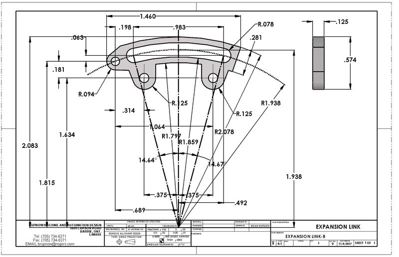
I can tell right now---there's going to be a lot of Voodoo in this 'expansion link' which seems to be the heart of the reversing mechanism--and I need two that are identical. Probably my best bet is to tack-weld two pieces of 1/8" plate together before starting to do any cutting or shaping. In fact, since I have a 3 jaw chuck mounted on my rotary table, it would probably be a good idea to attach a 3/4" round handle to the plates right at the center of the arc in the plates so that I can mount the rotary table with the central axis of the chuck vertical. The holes are not going to be a problem--I can use the DRO on the mill to locate and drill them. Cutting the arc shouldn't be a problem---in theory. The .078" radius on the ends of the arc dictates a 0.156" endmill, which I can buy locally. My rotary table has no "stops" that can be adjusted on the arc, so I see a lot of very meticulous angle watching because it will take repeated cuts all starting and stopping in exactly the same spot to cut that arc.
p3wm9M.jpg
 
Machine a piece of 1/8 plate to the full dia just over 4" and finish of everything
you will have room to make extra in the blank and have plenty of room for clamping.
 

Latest posts

Back
Top