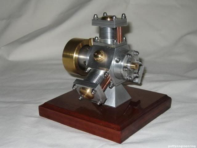
anyone interested in a radial team buid

Home Model Engine Machinist Forum

Help Support Home Model Engine Machinist Forum:

This site may earn a commission from merchant affiliate links, including eBay, Amazon, and others.

10 sets connecting rods - 100 % complete
10 collets - 40 % done
10 flywheels - material cut up

Have been busy with 2 large projects for work, one ships tomorrow morning and the other Monday.
Will finish the collets then start on flywheels. I don't want my machining to drag into the holidays
as there are gifts to make for family, including a new grandson. Now I just need some ideas, got any?


10 steam chests: 100% done
10 port flanges: material on the bench
10 orbital valves: did 4 in steel, turned out like crap, so switched and am now doing them in cast
iron, 1 done, looking way better

There will be a small delay, as I am leaving town tonight for 7 days....

Joe
 
t_ottoboni said:
I was planning to use cast iron for the pistons, the same i used for the liners. Is there any problem using the same material for both? If so, I think I could use aluminum or brass (maybe fosforous bronze too).
For the wrist pin, is it ok if i use shafts scavenged from old printers? They would be like 3.95mm, so they'll slide nicely in reamed holes in the con rods.

Actually Cast Iron is called out for the Liner and Piston, I guess they make a good combination. I'm only changing the Piston material due to the mess the Cast Iron causes. I also scavenge parts from discarded machines ... not knowing what the material is ... you will have to decide. The size, however (3.95mm), may be a problem. A bit loose for the Con Rods and pin won't want to stay in the Piston it may rub against the Liner. You could ream the Piston to 3.95mm or maybe a little Loctite applied during final assemble. In any event try it out and see what works. ;)


Pat
 
I am about 80% on the bearing case.

Does anyone know what is suppose to go into the m5 hole. I am assumine that it is for oiling or a vent. Any ideas?
 
chrispare said:
Does anyone know what is suppose to go into the m5 hole. I am assumine that it is for oiling or a vent. Any ideas?

Its for oiling, I made a small oiling cup just to tidy things off.

I also made a small brass tube to screw into the exhaust, again just to tidy things up.

I'll have a look to see if i've got a picture, my engines packed up ready to go to London for an exhibition.

Stew

Her you go

Pic63.jpg


You can see the bits I added.

Stew


Thought I would post a few pictures ...


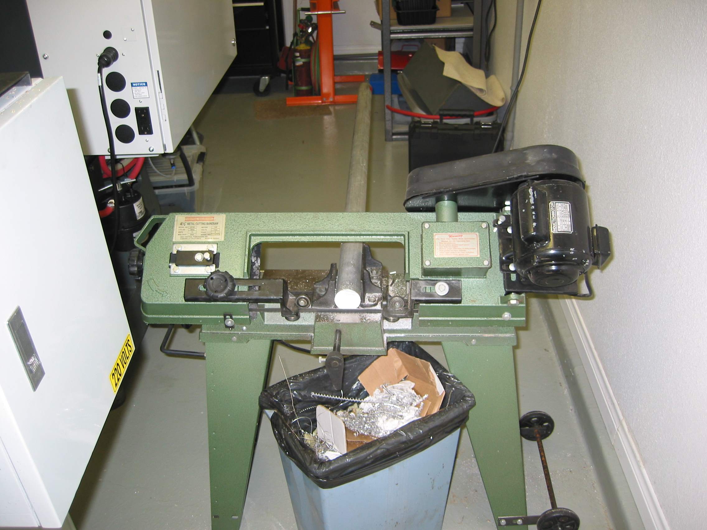
Here is where it all started ... 2" x 8' Aluminum stock ... cut so that I could make 3 cylinders at time.
TM6 3286_IMG.jpg


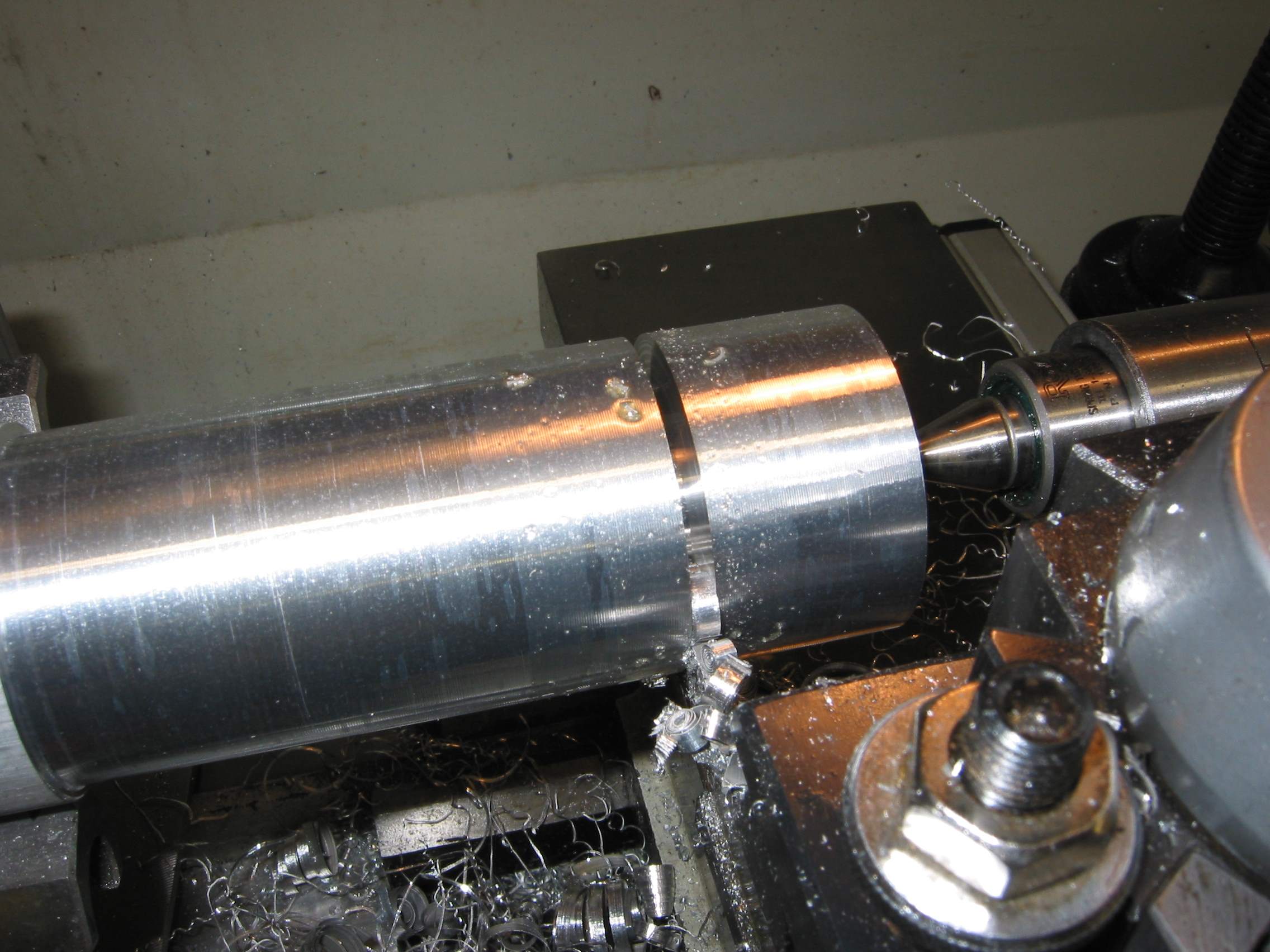
Turned it down to about 1.8" then cut in 3 pieces (this should look familiar see Stew's build log).
TM6 3288_IMG.jpg


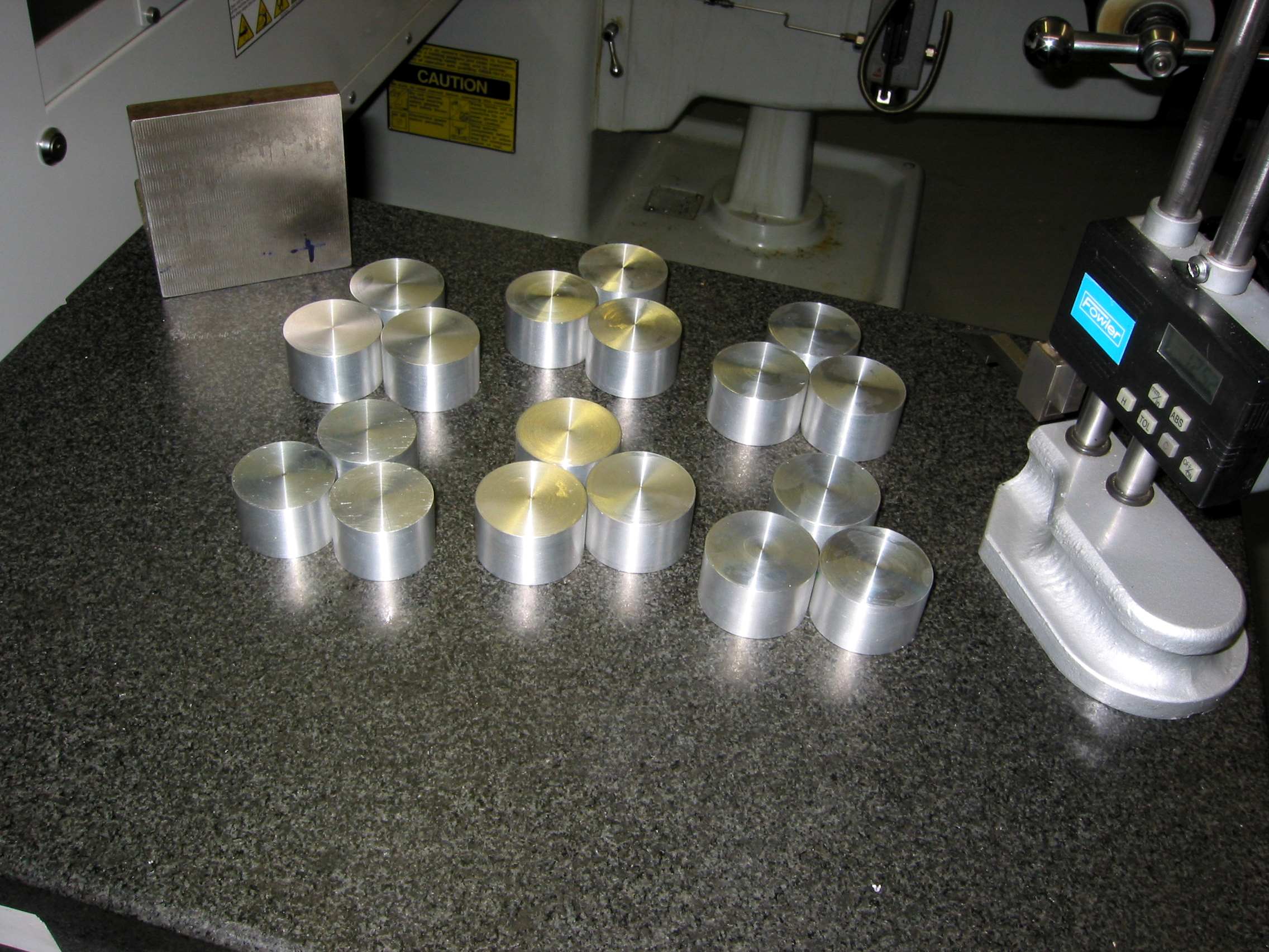
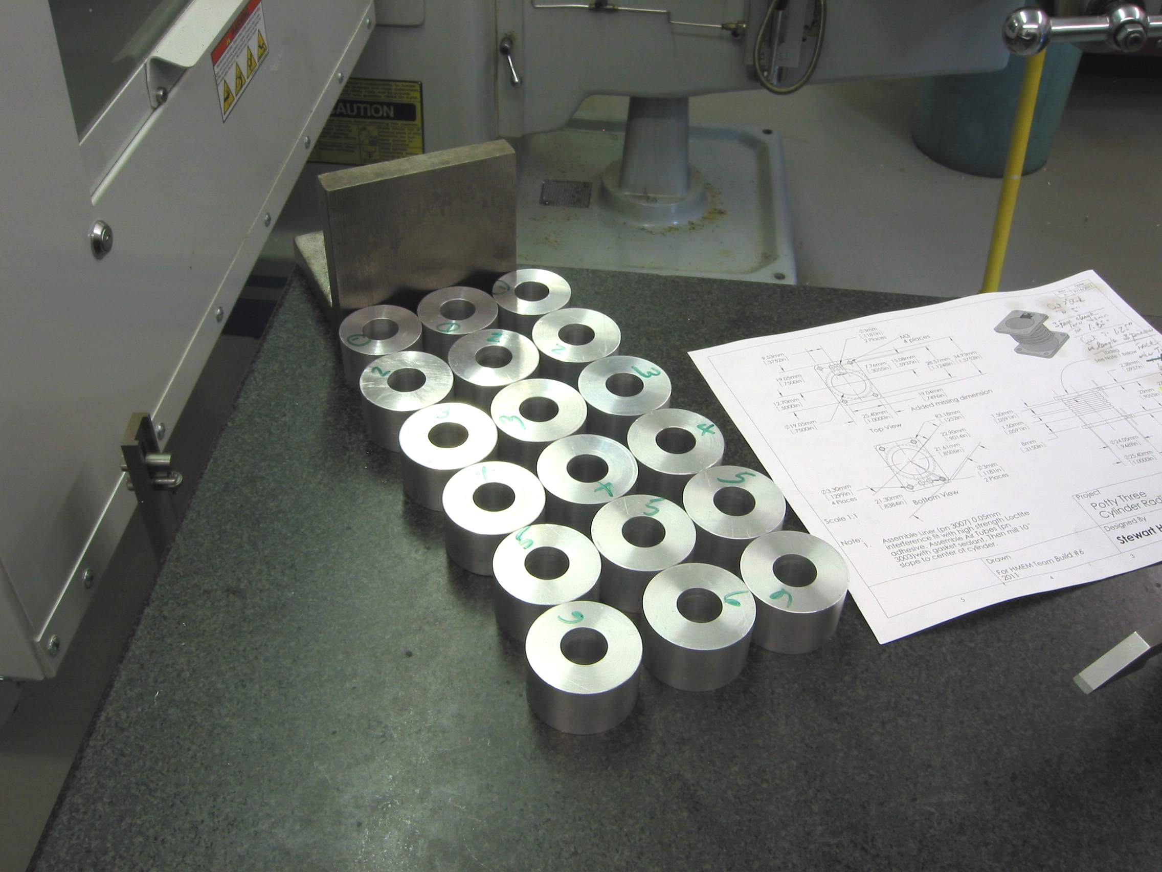
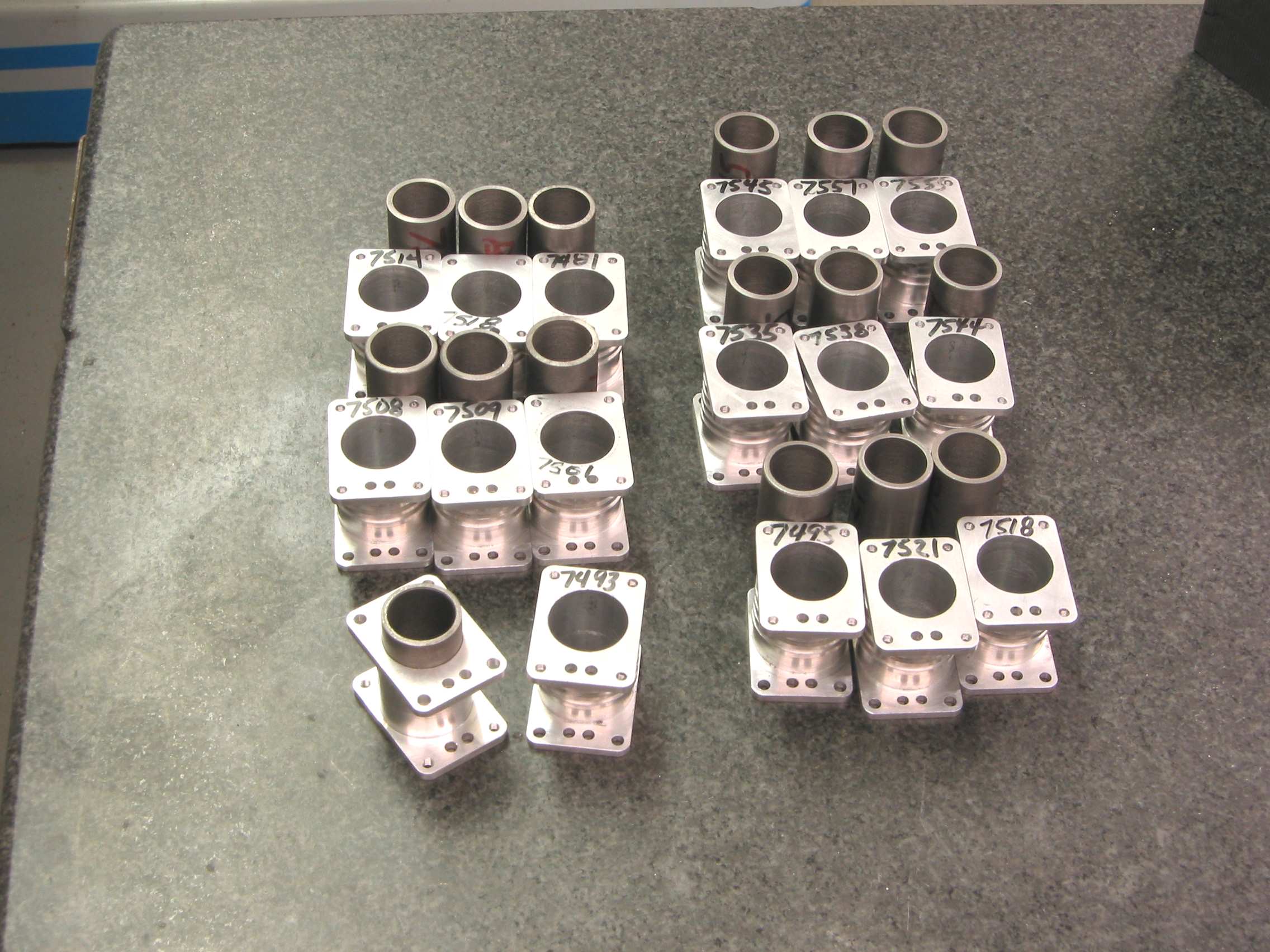
Here are 18 future Cylinders 3 extras
TM6 3293_IMG.jpg


All 18 with the .75" hole for the Liner
TM6 3297_IMG.jpg


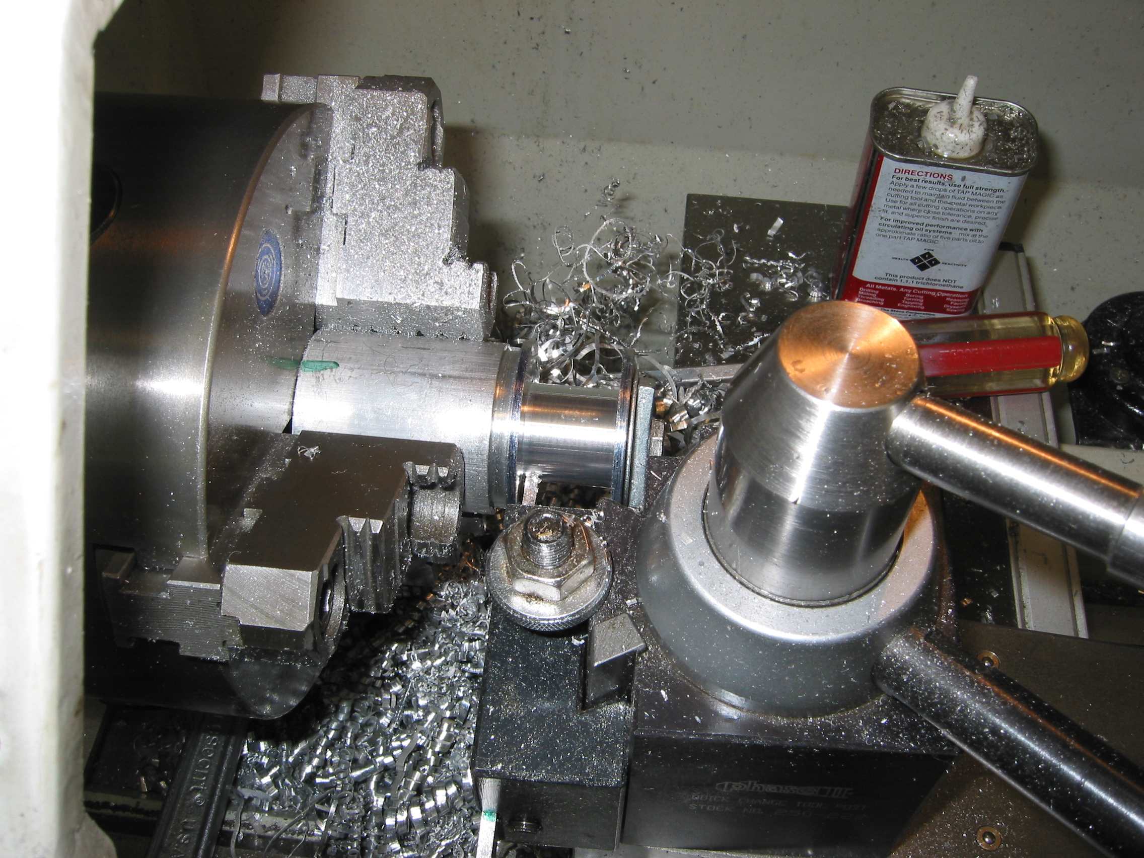
Machining the fins OD using a cutoff blade ... last cut .002 or less. Using a maderal.
TM6 3303_IMG.jpg


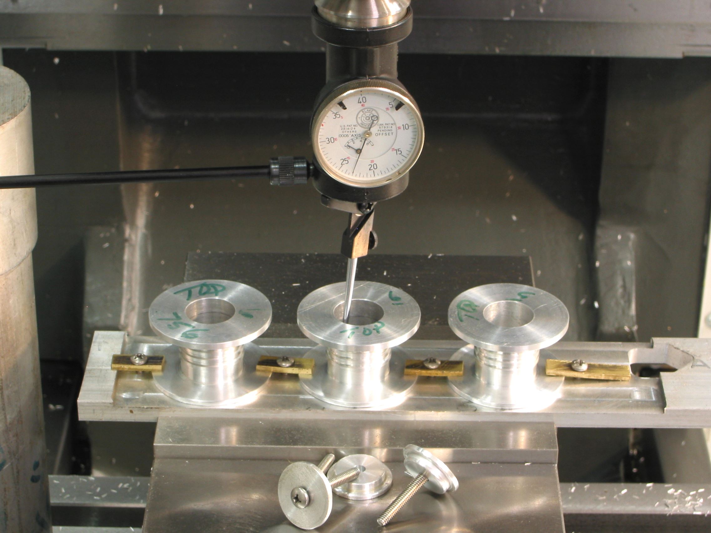
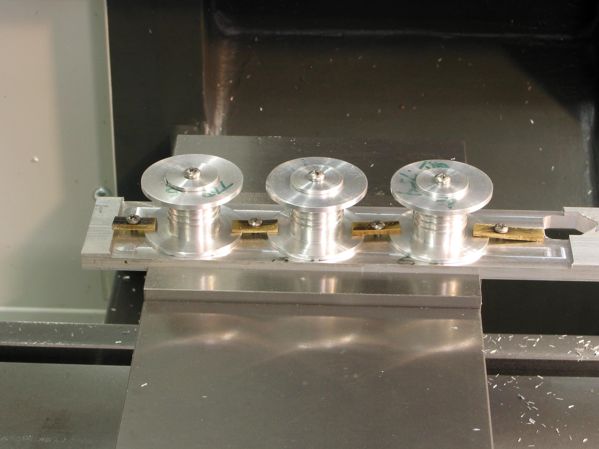
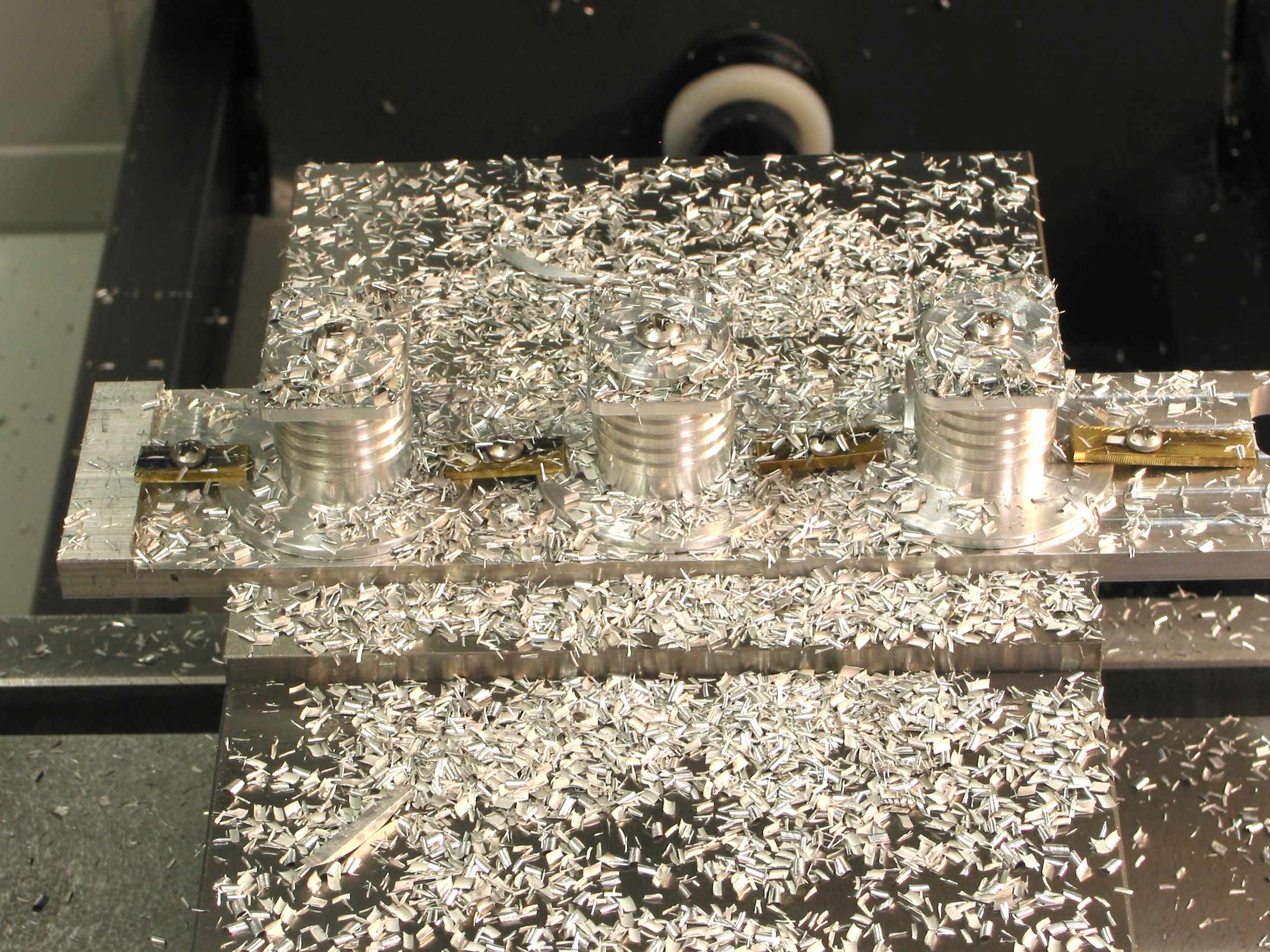
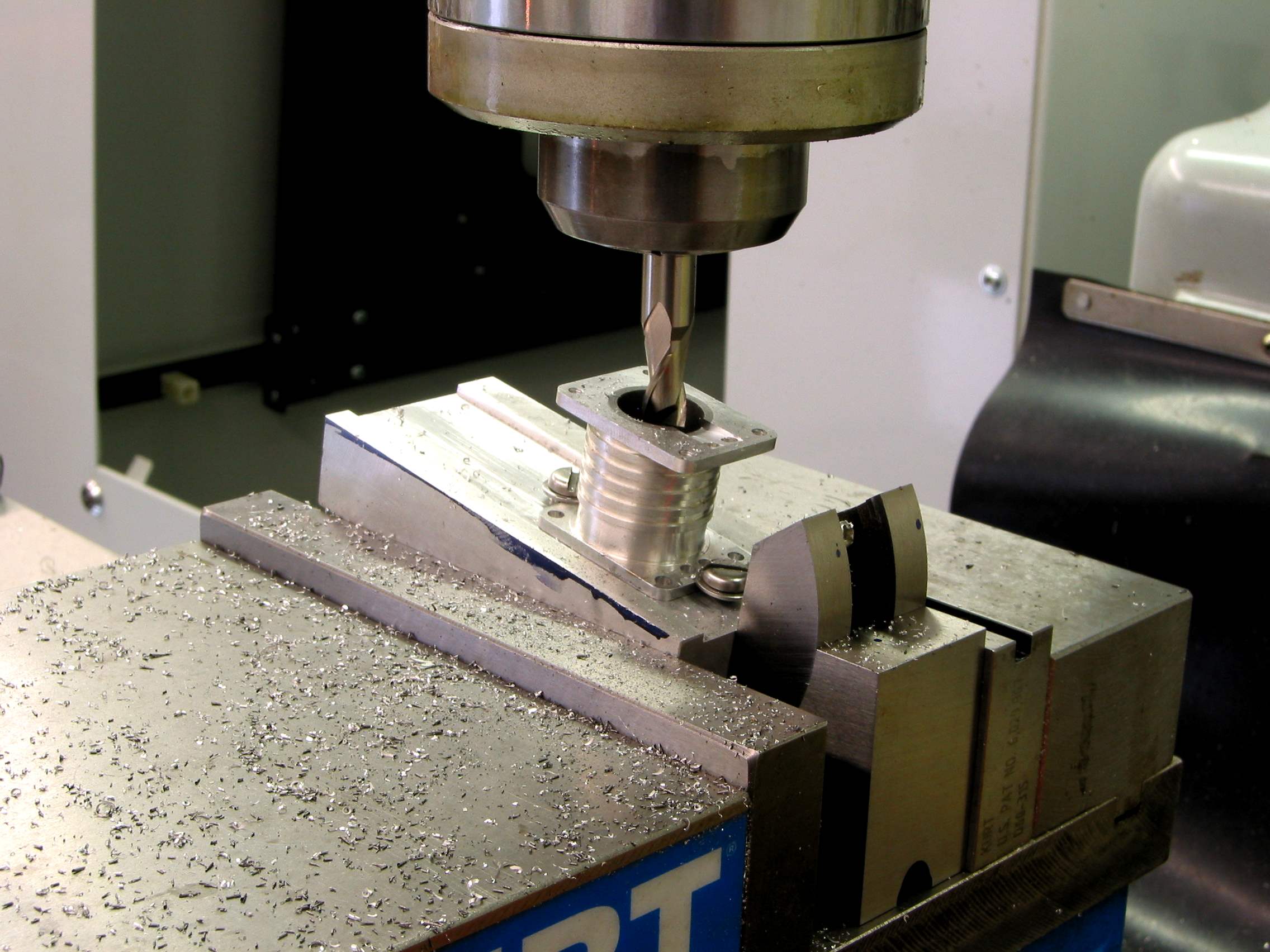
Jumping ahead a little. This chunk of Aluminum was milled down about .1" while in the vise.
This insures that the Cylinders are perpendicular to the spindle. The bottom was machine
on the lathe so it is also be perpendicular the hole. The Co-axial was used to find the center to set
G54, G55 and G56 XY locations on the CNC. The XY was adjusted for zero deflection while the
spindle was turning at about 50 RPMs. Once done the tops caps were installed to provide the hold down
force while machining the top sides. This operation Drilled, Taped and formed the rectangular top.
TM6 0017_IMG.jpg


Ready to push that start button ...
TM6 0012_IMG.jpg


After about 4 minutes this is what you get ...
TM6 0015_IMG.jpg


To be continued ... I have about 6 more pictures that I will post later.


Pat

 
Continuing on ...


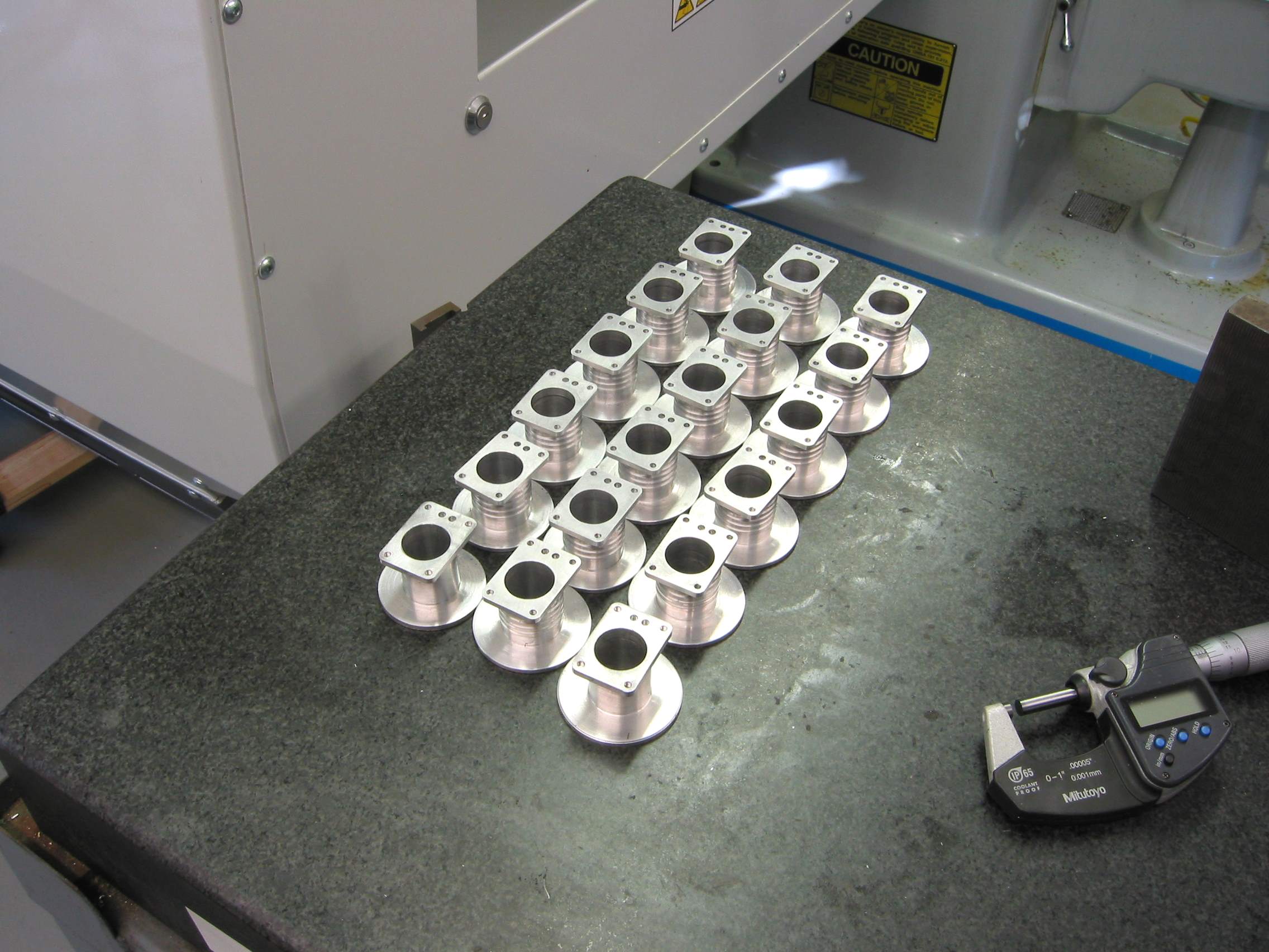
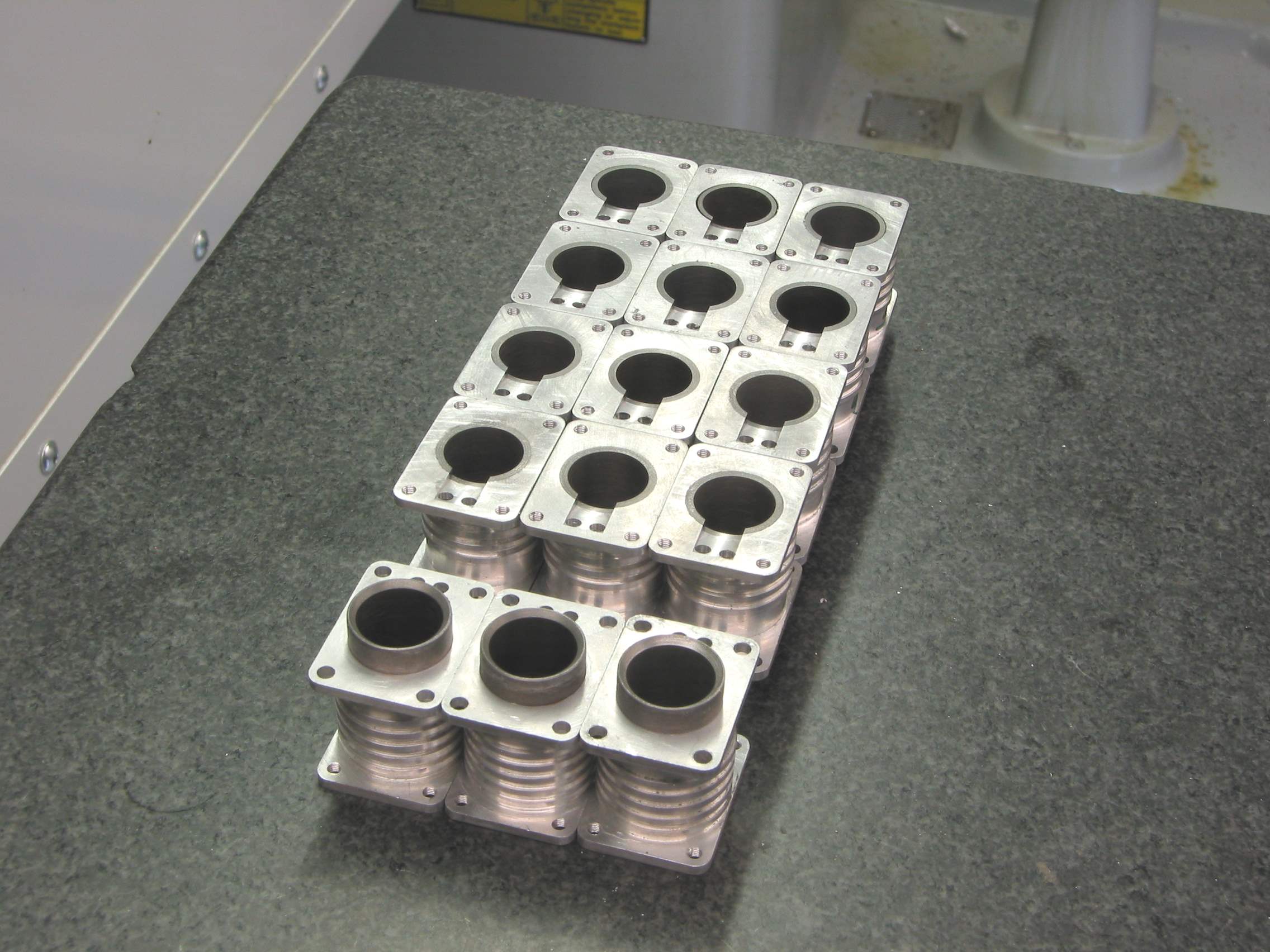
After repeating it 6 times I have all 16 ... if you look carefully you can see that I lost 2 Cylinders to
dumb mistakes. Now I have only 1 spare. ::)
TM6 0020_IMG.jpg


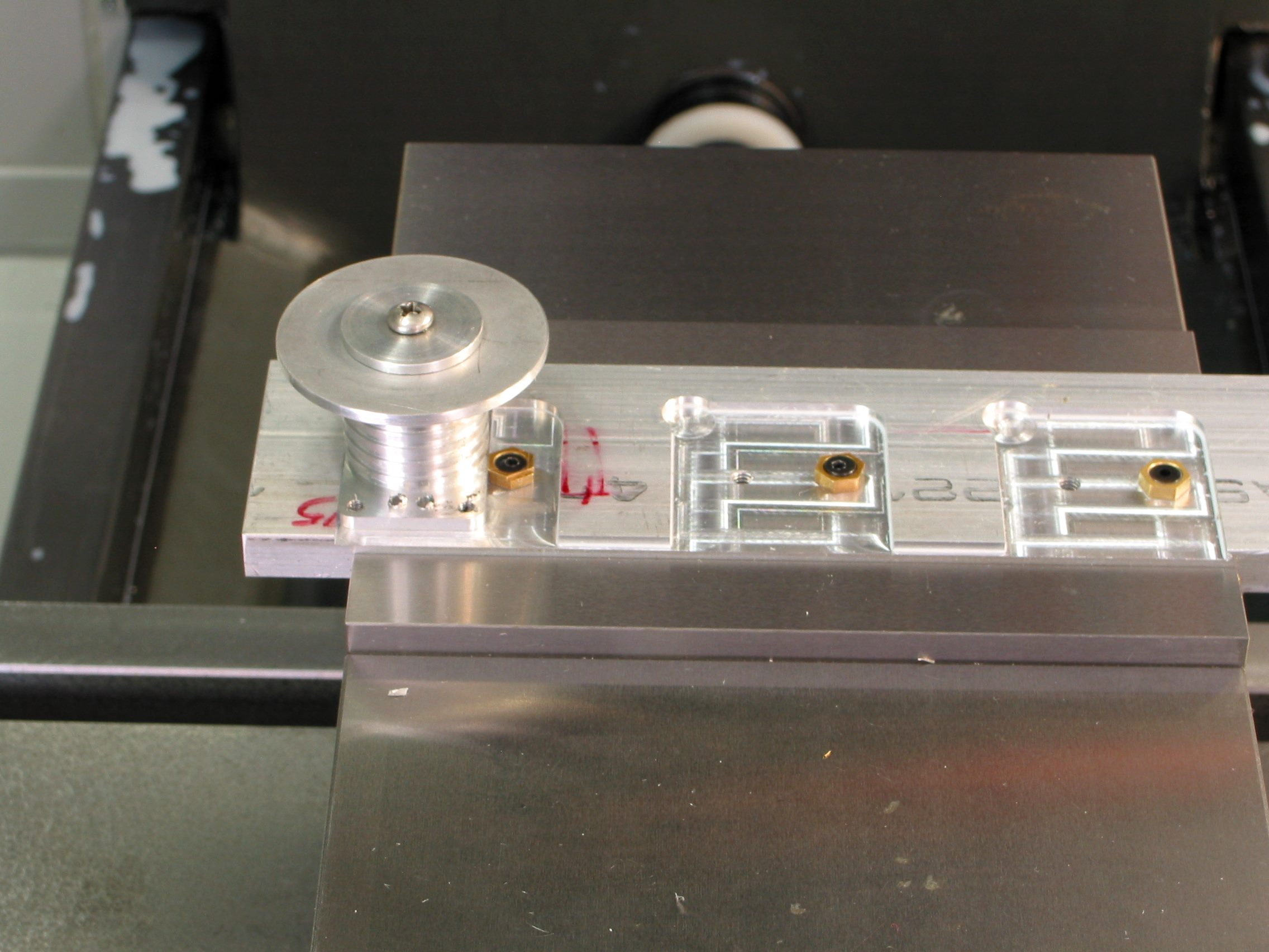
I repeated the process for the bottom. Using a different fixture.
TM6 0019_IMG.jpg


Here all 16 ready for the Liners.
TM6 0024_IMG.jpg


Measured each Cylinder and turned down the Liners OD so that I would have about a .001" - .002" interference fit.
TM6 0025_IMG.jpg


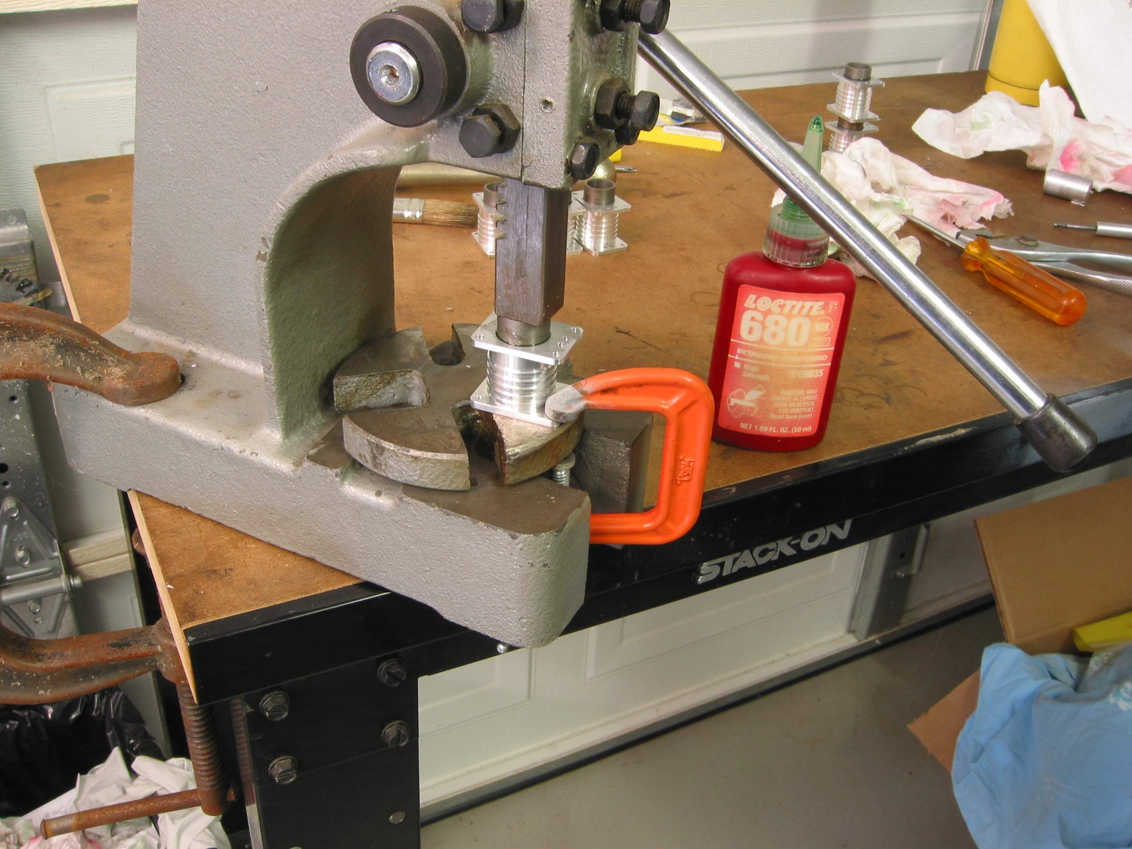
I heated the Cylinder just enough so that the Liner would drop in ... if not I added a little pressure. :p
Using Loctite 680 for sure tight fit.
TM6 0048_IMG.jpg


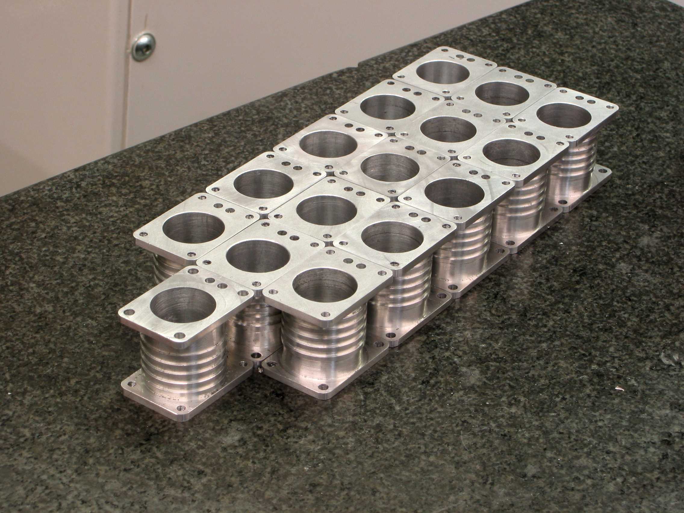
Another fixture to mill the 10 degree slope ...
TM6 0054_IMG.jpg


Finally these only need a little dressing and they are ready to go. :)
TM6 0057_IMG.jpg


Each Cylinder was then honed for a smooth finish.

That's it for now. Hope to get the Pistons done early next week.


Pat


Wow Pat that was a neat bit of machining, I always marvel at the capability of CNC and the guys who work them.

Stew
 

Pat, those cylinders look great! It's quite impressive how much work everyone has been doing on this build. What kind of mill

did you use to profile the cylinders? Nice fixturing also.
 
Stew ...

Thanks ... Yes CNC is nice to work with :), but I still do a lot with the manual.

Mike ...

Thanks... I have a Haas TM-2p with Rigid Taping, Wired for 4th axis, high flow cooling pump, programmable nozzle and 10 tool ATC.
Sure would like to get the 4 axis ... maybe someday.
I'm thinking I might use it for pistons ... we'll see.


Now the good stuff ...

Received your con-rods ... fantastic job :bow:. Looks like they went for a nice tumble. Very nice finish. Thm:

I ordered and received some 4mm drill rod. After a little rod finishing they fit nicely.
With a little run in they will work perfect.

I have a plan for the pistons ... hope to get to it Monday. Just need to figure out a holding method.
Then do a few samples to see how the Con-Rods will fit. Then ... make them.

Will keep you posted...

Again ... Thanks guys. :) :)


Pat


Dale,

Looking forward to getting them.

Thanks,

Pat
 
Yes also looking forward to getting them.

Crank shaft and crank return were posted today except for Otoboni, I have sent him a pm with regards to his address.
 
Dale,
Got your parts today ... very nice.

Fits perfect. Thm:

Nice touch with the extra tubing and a picture of the builder (I guess :big:).

Thanks, :)

Pat
 
Thanks Pat I am not sure how the tubing is going to fit so I thought it would be wise to include extra. That was some shipping they were mailed monday afternoon . Dale
 
got the heads and tubing today. looks very nice. ty Dale
Pascal
 
About the Piston and Con Rods ....

Path said:
Stew ...
....
My thoughts would be to increase the 9.46 square a little (the amount to be determined) and machine a radius at the four corners ... in short
follow the picture.
....

See reply #268 for additional information.

I was able to test the Piston and Con Rods today and I have changed the 9.46mm square hole to 9.86mm with a 1.50mm radius.
This allows a little wiggle room for the Con Rods. So far no other changes have been made for that assembly.

However, you may need to file a small radius on the Con Rods during assemble for a better fit due to varying part dimensions. You'll have to decide that.
I haven't tested at the assembly level yet, but it should work. It looks good using the CAD.

T-ottoboni (or anyone else) ... If you like I can send a new Piston Drawing #3009 Rev B.


I started to build a fixture to machine the 9.86 hole and Wrist Pin hole for the Piston ... hope to have it mid week. :D :D


Pat


Latest posts

Back
Top