AlphaVictory Engine Build

Home Model Engine Machinist Forum

Help Support Home Model Engine Machinist Forum:

This site may earn a commission from merchant affiliate links, including eBay, Amazon, and others.
Dean; How do you cut a ceramic sheet? I think I will try the phenolic, thanks for the offer, I may need it if this does not work.

Kcmillin; The finish came out nice. All I did was start with some 230Grit and worked up to 600, almost like chrome ;D


IronHorse
 
Ironhorse, you can cut it with scissors. It's not hard like ceramic tiles. It's woven, like a thick fabric.
Offer is open if you change your mind.

Dean
 
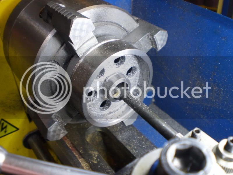
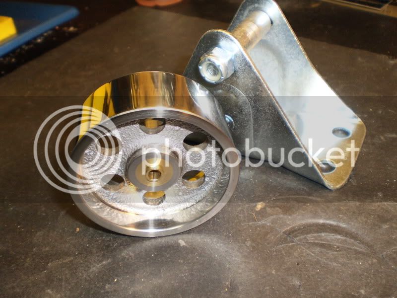
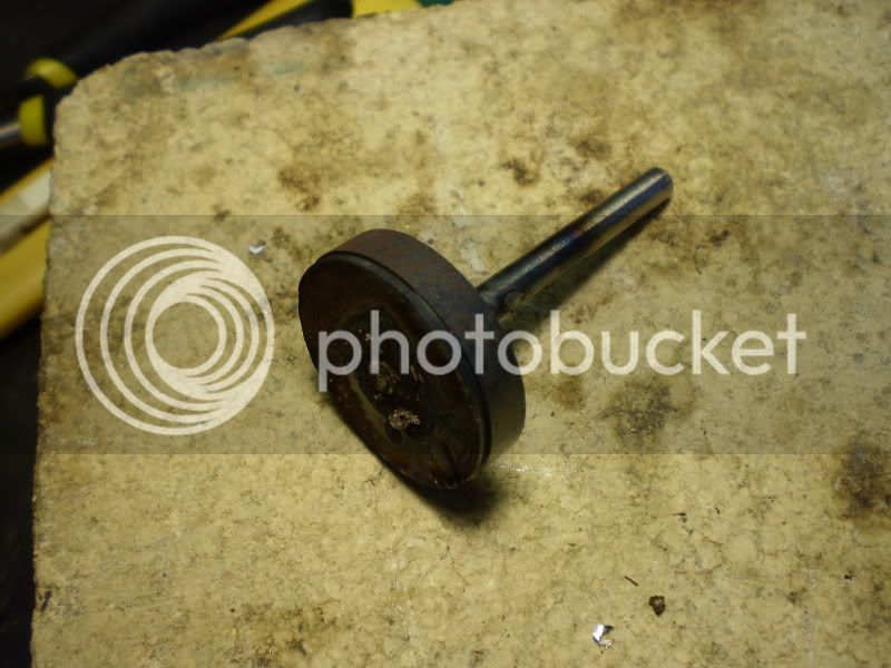
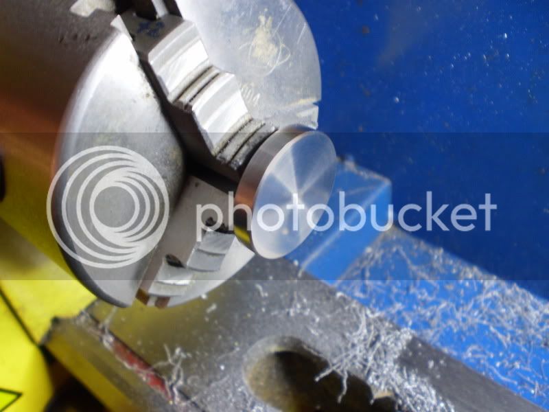
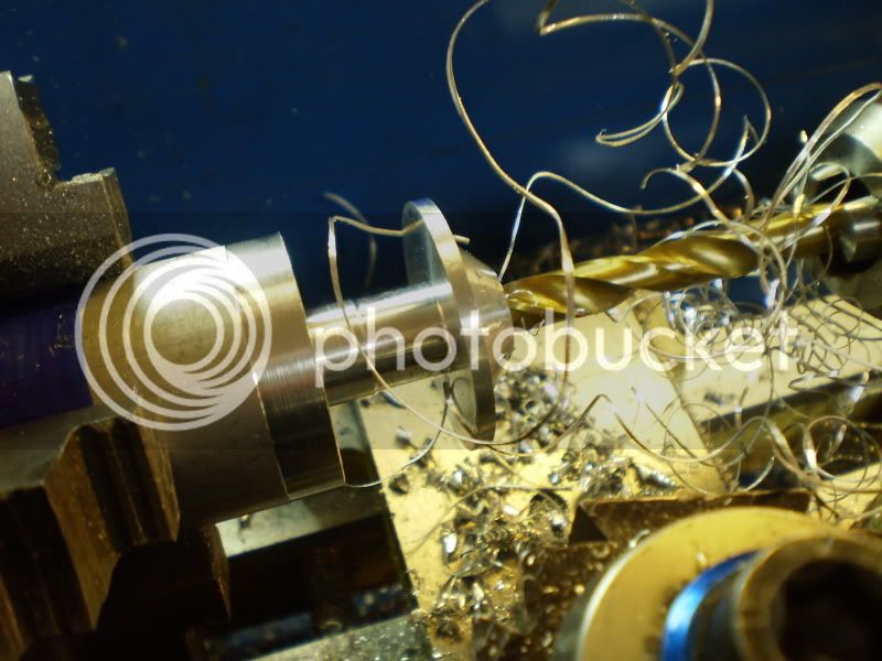
I was shopping at Princess Auto (Canadian farm/auto supply) and I came across this. I guess it is called a caster wheel, but all I saw was a $6.99 already half machined flywheel ;D They had a few different sizes and I picked up this 2 1/2" one. The only true round surface was the outside of the rim, so I centered it in the 4 jaw and did most of the machining from this setup. The hole in the middle was too big and not in the center so I bored it out oversize. I then cleaned up as many surfaces I could. The outside rim had a slight crown on it so I cut that down while it was firmly gripped in the chuck. The wheel was then flipped and held on the inside of the recently trued rim. Some 230 to 600 grit sandpaper really brought out a nice shine. Later I press (Hammer) fit a brass plug in the center, re-chucked it and drilled and reamed the center hole. Surprisingly it runs true, and was easy to make.

P3010261.jpg


P4230250.jpg


I have read that Alpha engines have a higher compression ratio then other types, so I want to start with a heavy flywheel. After machining it weighed 1/2 Lb.


IronHorse
 
Nice idea for a flywheel source. It turned out great. I like that you left it rough on the spoked area.

Kel
 
Nice looking flywheel there IH. I like the overboring, and plug approach to getting a true center. Nice tip

Cheers,
Phil
 
IronHorse said:
Trout; I have always liked the Rat Fink, sort of the anti-Micky ;D

Yep! Definitely the anti-Mickey. Don't know if you guys have seen it but there is a DVD called "Tails of the Rat Fink" that is a documentary of Roth. Even has some home movies of him. I grew up in the LA area as a kid. Roth used to paint custom T shirts at the county fair. He was well known in the car culture in Southern Cal back then. Have a look at who keeps my engines company on the shelf!!

Back to the topic: Love the engine and the layout of it. Great looks and concept. I'll have to keep an eye on this one. Always looking for another type of engine I have not tried yet.

IMG_2252.jpg
 
Great idea using a castor wheel for a flywheel.

Harbor Freight puts theirs on sale quit often.

SAM
 
I am always on the lookout for cheap ways to buy materials. This one is great, I never thought of it.

Thanks much,

Lee
 
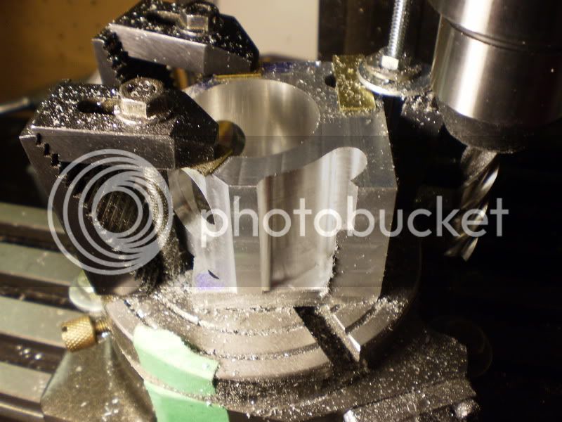
Here is the crankcase, It was the most time consuming part so far. I got to try out my new boring tool for the mill. It worked great and the supplied HSS toolbits cut like butter.


After squaring up a block of Ali, I milled the 45 deg cuts and bored the holes for the cylinders.
P1090250.jpg


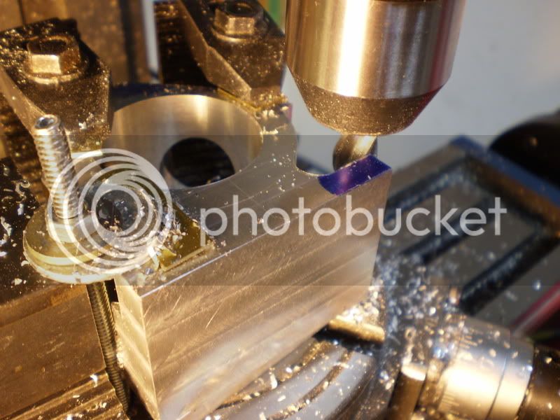
Here is the point that I realized that I should have bored the large hole first. :-[ I was a bit worried about the interupted cut, but all went well. ;D
P1160223.jpg


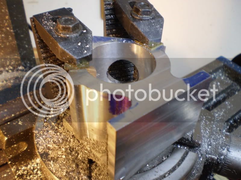
This was the most scary part. I thought for sure I would bust the mill, or the bit, or the work, or all three :eek: I started with 0.015" cuts, feed in the X, rotate the table, return, feed out X. I used tape to mark both extremes on the RT during the rough out.
P1220235.jpg


Next was to cut the material left on the "feet"
P1270251.jpg


Almost done, just have to tap the holes for the covers and cylinders.
P1290253.jpg


IronHorse
 
Good progress. That crankcase is coming out nice!

Dean
 
Very Nice indeed. Well done, those r/t setups can be quite difficult.

Kel
 
Time for an update. Here is the simple crankshaft for the engine. A disk of CRS and a length of drill rod soldered together.
P2150282.jpg


I then chucked it in the lathe to clean it up. I seem to have better luck if I thread the disk and turn a crank pin with a shoulder on it. Locktite in and everything runs true.
P2150284.jpg


Next was the crankshaft bearing holder. I turned the main body from Ali, then press fitted a spacer inside the bore to separate the ball bearings.
P2130280.jpg


Here is what it looks like so far.
P3080256.jpg


IronHorse
 
Truly elegant IH !! That caster wheel made a perfect flywheel too. Beautiful work.

Bill
 
Looks great, nice design also.
 
Coming together very nicely. The flywheel looks excellent.
Thm:

Kel
 
Very nice! Will be a really attractive engine.

Dean
 
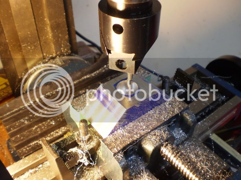
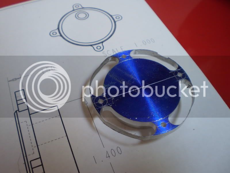
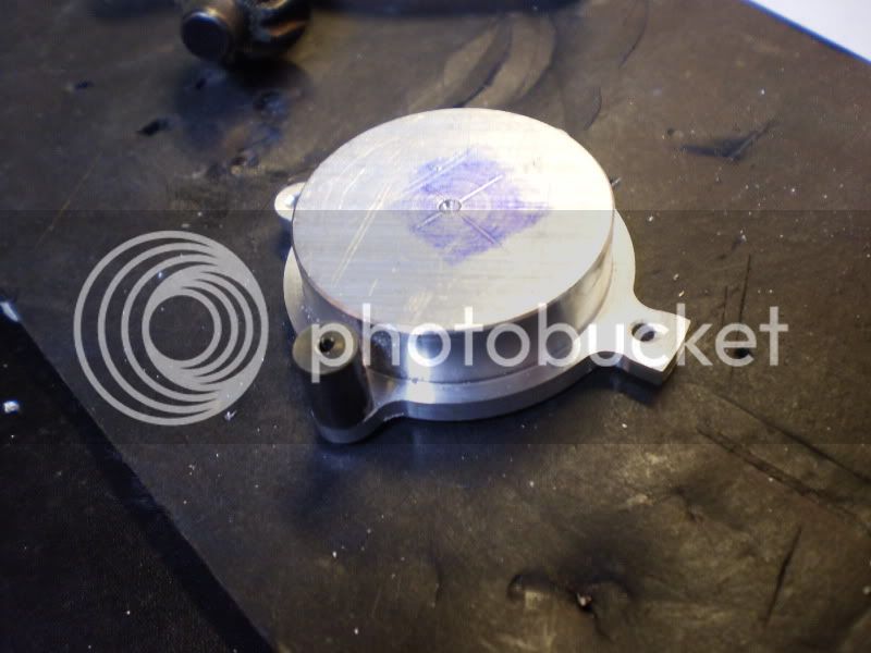
Work in my shop has slowed down a bit due to the nice weather, but I managed to mill out the front cover. I had to do some re-machining on my 4" rotary table that I got a while ago. I found that the hole was not in the center of the table, and the table its self was oval ??? I made a plug to press fit into the hole and chucked the table by the main bearing in the lathe. After center drilling the plug, I skimmed the outer face until it was round. It works good now as can be seen in the next picture. The milling operation left a thin consistant "ribbon" of material around the circumference.
P3210262.jpg


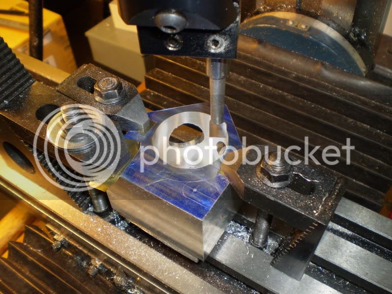
I made the cover extra thick so latter I could mill a "V" or some fins into it. I also used a "Filling Button" to get a nice radius on the tabs.
P3270263.jpg


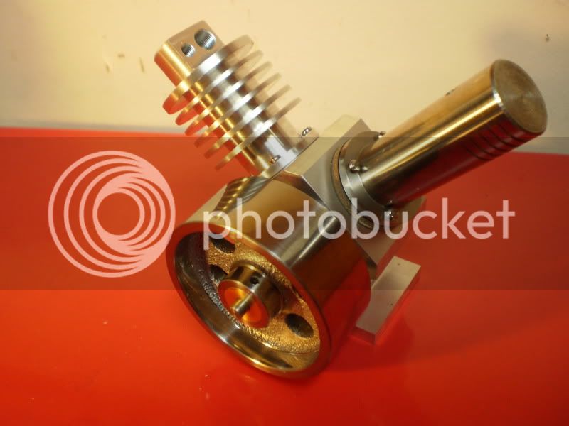
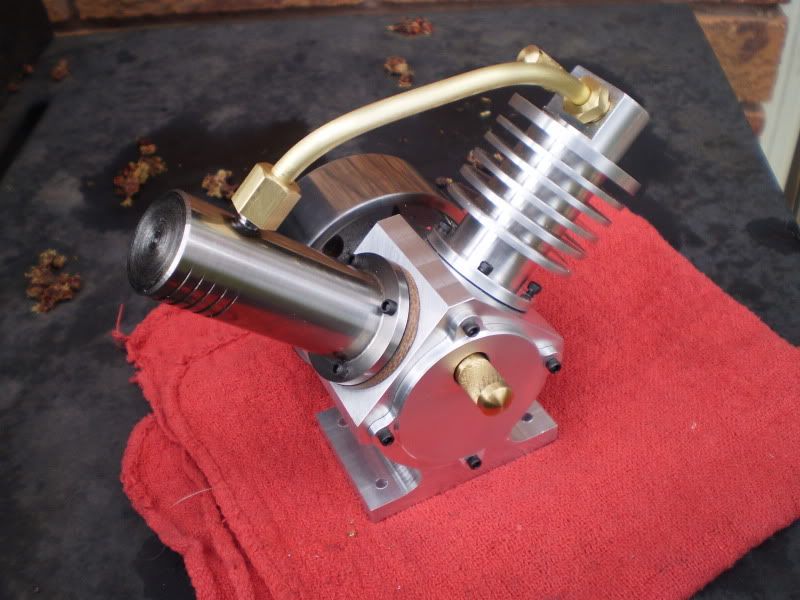
Here is a shot of the engine to date. I made the connecting tube without the re generator for now. I will test it in this configuration first and may add the regen latter. I have read that on small scale model engines, a re generator may actually hurt the performance.
P4110268.jpg


Till next time
IronHorse
 
Thats a darn nice looking engine. Can't wait to see it run. Are we there yet??? :big:

Chuck
 
Well, time to get back to the Alpha Stirling project. I have being busy playing with old gas engines and my Mustang all summer, but now the leaves are falling and the daylight is getting shorter, time to build engines ;D

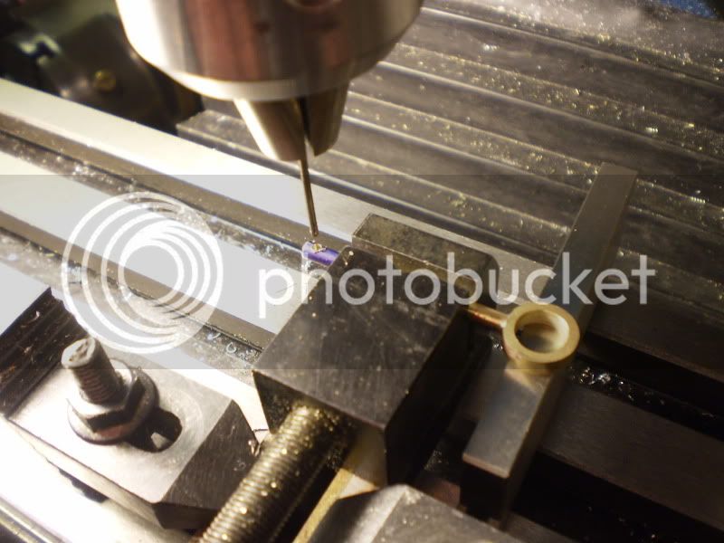
Next was to make the piston rods. These are simple creations made from 1/8" brass rod, silver soldered to a brass ring finished to 0.374" ID ( I love over/under reamers ;D) A 1/16 hole was drilled in the end for the wrist pin.

P2200255.jpg


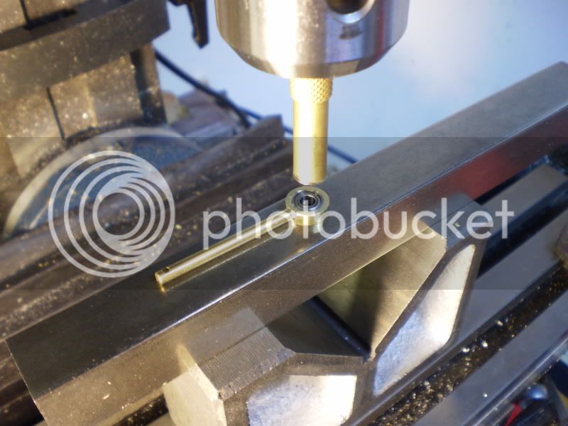
I heated the rod in the toaster oven and cooled the bearing (0.375" OD)in the deep freeze. I used a brass punch in the mill chuck to press the two together. I was surprised how easy they slid together, I was worried that I would put too much pressure on the bearing.

P2210257.jpg


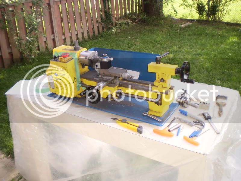
Time to make the graphite pistons. I got a 10" piece of 1.125 diameter Graphite from a friend for free, but I needed only 3/4" pistons. That meant a BIG mess was going to happen. I decided to move the operation into the back yard. I covered a table with plastic and went to work.

P9190058.jpg


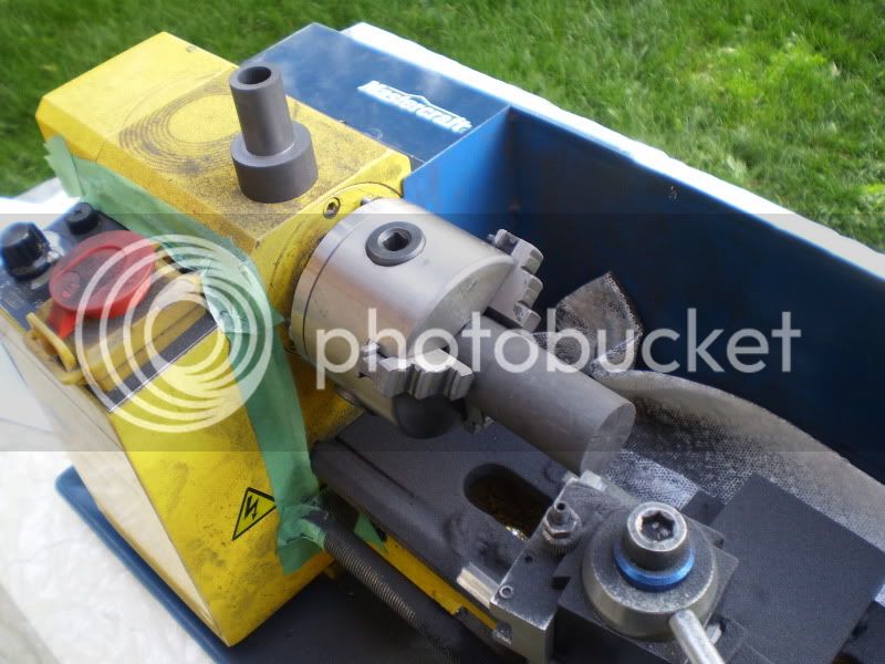
Here is the second piston, you can see the pile of the nasty stuff from the first one. I used those cheap carbide-tipped cutters and they cut well. I cut the pistons to within 0.010" of there final diameter and moved the operation inside for the final fit.

P9190057.jpg


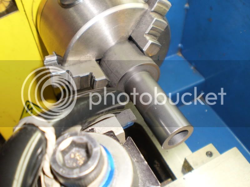
I hooked up a vacuum with a 1/2" tube at the tool post and slowly cut it down to about 0.002"
over. I then used some 1000 then 2000 grit paper until it was a tight fit in the cylinder. Next it was parted off to the correct length.

PA160075.jpg


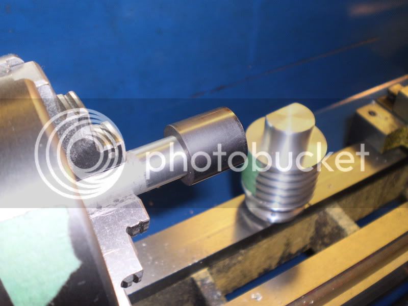
The last operation was to make a Mandel to mount the finished piston on. I used alternating 2000 grit paper and plain photo copier paper until the fit was nice and smooth.

PA160077.jpg


I roughly assembed the engine and it feels very smooth and if I block any of the ports there is a lot of Compression/Vacuum. I just need to make a few gaskets and do a final fit on the connecting tube and I hope to get it to run. :big:

IronHorse


Very cool, you do nice work! Can't wait to seeing it running. What kind of lathe is that? If you don't mind me asking. I'm currently in the market...

-Blake.
 

Latest posts

Back
Top