A new ignition circuit

Home Model Engine Machinist Forum

Help Support Home Model Engine Machinist Forum:

This site may earn a commission from merchant affiliate links, including eBay, Amazon, and others.
Finally got my engine to run for a little bit. ( N0 fault of the circuit. Had other issues.)


Battery wire came loose as I was trying to start the engine.


Now when I turn on the switch the LED is on constantly but dim when I turn the engine over the LED flashes brighter but plugs don't fire.

What do you think is the problem? Do you think I could have fried the Hall sensor or what?

Help!!


Ron

Ron,

Classic fried hall sensor...

John
 
Thanks John, but you know what? I went out today and switched it on and tried it and it works!! :wall::wall: It fires the plugs just fine.:shrug::shrug: I have extra sensors if I need them though.

Ron
 
Thanks John, but you know what? I went out today and switched it on and tried it and it works!! :wall::wall: It fires the plugs just fine.:shrug::shrug: I have extra sensors if I need them though.

Ron

Hi Ron,

The output transistor in the hall sensor is partially destroyed (on the internal silicon die, it's made up of several small transistors in parallel - I have a microscope picture somewhere we took during a failure analysis of hall sensors at work after the hall sensor was "de-lidded"). In any case, the output transistor(s) is leaking current and that's what's keeping the light on dimly. You'll likely get a stronger spark if you replace it.

I had exactly the same problem multiple times because of poor grounding (my own fault) with exactly the same symptom (light on dimly, then full brightness when the hall triggers)

I've since switched to the Optek OH090U. Those things are nearly indestructible! I've literally had sparks jumping from the ground lead on the hall sensor to the engine frame after a loss of ground and they survived!

To all... Keep your grounds secure, fool-proof, and with a short run to the battery (-) terminal and you'll keep risk of sensor damage to a minimum... When the plug fires, the energy transferred from the spark electrode to the engine "ground" has to go somewhere. If it can't return through a good ground to the (-) on the battery, it'll arc to the hall sensor if it can and return through the hall sensor wiring. That is not a good thing...

Or use the OH090U and ground your engine through 3 feet of wire with an alligator clip to a tiny screw like I was doing! :eek: LOL.

John
 
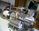
Some one had asked a while back if there were any engines running on this circuit, well here is one. My very first IC engine , a flat 4 cyl boxer 4 stroke. A Mastiff by designed L.C. Mason in England back in the 70s.


Made out of bar stock, no castings.


Ron
 
thanks for sharing
but please post this in finish project also
and some pictures

Thm:Thm:
 
I've already posted this to this photos and videos section, but here it is again since it's running using this circuit.

[ame]http://www.youtube.com/watch?v=DoI33CuWYsU[/ame]

John
 
That's super John. I Have plans for a Webster and a Kersel and will have to give them a shot some day.

Thanks for the comments.

Ron
 
I just got a PM from another member about problems he was having. The A1121 hall sensor is problematic for him too as it was for me. They can be damaged by high voltage VERY easily.

The OH090U fixes the problem. They are very robust...

The big problem with the OH090U is availability outside the US. The fellow that needs them is in Scotland.

Any advice from other members on the other side of the pond?

Thanks!
John
 
Hi John
Thanks for the reply to my message and the advice about the sensors
I have finally gotten some OH090U sensors sent from the US and straight away my problems with fried components went away
Now I just need to work on getting the fuel setup correct and getting the engine to run for more than a minute or two
The ignition circuit is perfect, thanks for posting it
Regards
Dougie
 
I'd just like to add that if your fried Hall sensor was because of something silly that you did, like having a wire fall off or something, that's one thing.
But if you were/are regularly blowing sensors then it's probably due to poor wiring practices. That problem should be eliminated first.
It's not usually a good thing to insert bigger and stronger parts to overcome a fundamental wiring problem. That issue will eventually come back to haunt you.

The circuit should work properly with almost any Hall sensor if your wiring follows good practices.

i.e. keep all wires as short as possible, one common ground point etc. etc. You've heard it all before.


Sage
 
Hello Guys
I´m new here in this forum and i was reading this Thread with much interest. Today i received my IGBT order and breadboarded the circuit. I saw that some folks here in Europe have trouble finding some parts. I didn´t have the 2N4124 Transistor here, so i used an easy to obtain BC 547 as a substitute. It works just fine. Same with the Hall sensor. I`ve been using the unipolar "H 501" Hallswitch sensor for a long time on different ignition systems with success. So do i here. You can buy the sensor at Conrad Electronics or even on ebay (might be easier for some people). I will attach the datasheet. At the moment i am designing a small circuit board with solderpads for the power, the coil and the sensor lines. I don´t use the terminal blocks cause they sometimes give you a bad connection. And i don´t want to fry my sensor.....
If anyone is interested i can post the board here or send it via PM. Thanks to all here for the information specially to jgedde and dsage for sharing this excellent circuit and givin`so much help.

Stefan

View attachment Datenblatt Unipolarer Hallschalter H 501.pdf
 
Hi Guys:

Just one last minor note. I did some testing of the circuit at the extreme ends of operating conditions. I found that if you are running the circuit on four dry cells (6v or a bit less) and you are waving the magnet in front of the hall sensor, sometimes the LED lights but you get no spark. It was pretty intermittent and may be fine depending on your coil. It worked fine at engine running speeds.
In any case I found that changing R6 from 39k down to 22k made the spark more reliable waving the magnet (i.e. very low rpms like cranking speeds). If you have issues like this change R6 to 22k.

Thanks

Sage
 
i realize this is an old thread but would anyone here have built a couple extra ignition circuits that they would be interested in selling, I am not good with schematics and soldering
 
Performing a bit of thread necromancy here, and moving a previously point-to-point conversation out here, in case it benefits someone else who scratches their head about this:

I'm interested in using this design to make the ignitions on ancient chunks of farm machinery that we use mostly for show purposes, more reliable. I don't want to significantly alter the engines, so using the points in place, rather than cobbling in a hall sensor and magnet carrier seems like a reasonable approach.

I'm wondering however, whether the dwell time at cranking speed with points, runs afoul of the "You're boring, I'm going to sleep" timeout you've built into the circuit. Not relishing the thought of what some of my battery-ignition, but hand-crank started engines would do, if the timeout effectively looks like super-advanced timing, at cranking speed!


If you were to use points to drive the circuit, it will be necessary to remove the condenser at the very least.

You raise a valid point about the dwell time triggering the timeout during low engine speeds and cranking. But, required dwell time is required dwell time and that's completely independent of whether a hall sensor or contact points are used.

Basically what I'm saying is that if you were to replace the points with a cobbled magnet and a Hall sensor, you'd have to consider the time the Hall sensor is triggered and make it match the behavior of the points. That said, it's much easier just to retain the points. As an aside they'd likely last much longer in this application since they'd be carrying no current and never arcing. However, I believe they'd need to be cleaned more often since a small amount of arcing tends to keep the contacts clean.

Worse comes to worst, you could always use a larger value capacitor in the circuit if timeout is occurring, but I tend to think you won't have a problem with just driving the circuit as-is with points.

I actually hadn't thought about that at all, and now that you've made me think about it, I'm wondering why this circuit works with the hall effect sensors at all...

I had previously (erroneously) assumed that with the hall sensor, the design de-energized the coil when the hall sensor stopped sinking current (the transition from sensing the magnet, to not sensing the magnet), and energized the coil again immediately afterward. Obviously this can't be the case, partly because that would imply that the coil was running with almost a full 360deg dwell, which seems unlikely to be healthy, and also because Jgedde has repeatedly mentioned the safety timeout for the system stopping with the hall sensor over the magnet, but nothing about needing to worry about stopping with the sensor away from the magnet.

Just to be sure that I was right about having been wrong, I hooked it up to my 'scope and yup, the coil output is de-energized until the hall sensor sees the magnet. It then comes up, and remains up for the shorter of either approximately 20ms, or when the magnet leaves, then it drops again until the next time it sees the magnet.

So now I understand how the circuit works, but I don't understand _why_ it works. With the hall sensor, the dwell duration is only the period between when the hall sensor sees the magnet, and when the magnet leaves its sensing radius.

At any kind of realistic engine speed, for anywhere that I can think of that's easy to place magnets (i.e., flywheel, crank) that time gets down into the sub-millisecond range pretty quickly. With wild gesticulation instead of actual number-crunching, at 60RPM, 1 degree of revolution is about 3ms. It's been a long time since I worried about performance engines, but dim memory says that's just barely enough to build field in a coil on a particularly cheerful and optimistic day.

Assuming people are shooting for running speeds in the high hundreds to low-couple-thousand RPM, does this mean that you're finding some way to coat 50 or so degrees of some spinning component with magnets, to develop sufficient hall sensor on-time? Or is there some other magic at work here?
 
Why it works is a cute trick of physics. The sudden inrush of current to a coil builds the magnetic field, the current required to hold this magnetic field is much smaller. The rate of collapse, and strength of, that magnetic field across the secondary winding of the coil determine the effective energy transfer.
Old ignition systems used resistance wire or a ballast resistor to avoid full current across the primary winding, this kept the coil from overheating at low rpm but limited performance at higher rpm.
So, dwell was always a balancing act anyway. At low rpm, you will almost always have enough current to get the job done. Those electrons are pretty quick. :)
 
Willray:

You didn't specify how many cylinders your "old time" engines have but I'll assume single cylinder engines.
It was also tough to weed out your exact question from your post.
But I think what you're wondering is if the default 20ms time out of the ignition circuit will play havoc with a very slow turning (single cylinder) engine such that the spark would occur too quickly because of circuit time-out rather than the points actually opening.
The 20ms time-out may be too short for a SINGLE CYLINDER engine at hand cranking speeds making the spark occur sooner than expected. And, like you said, appear to act like a "super advance" at low rpm's.
The 20ms can be increased by increasing the value of C2. It wouldn't matter if C2 were increased in value to provide something as crazy as one second of time-out. It's just there as a safety circuit to protect the coil.
BUT
Personally I would leave the 20ms time-out as it is. The engine will soon start and be up to a reasonable running speed and a bit of extra advance while cranking should pose no problem.
Don't forget you should adjust the timing of the engine with a timing light and the timing marks of the engine.

Sage
 
Back
Top