A new ignition circuit

Home Model Engine Machinist Forum

Help Support Home Model Engine Machinist Forum:

This site may earn a commission from merchant affiliate links, including eBay, Amazon, and others.
Performing a bit of thread necromancy here, and moving a previously point-to-point conversation out here, in case it benefits someone else who scratches their head about this:

I'm interested in using this design to make the ignitions on ancient chunks of farm machinery that we use mostly for show purposes, more reliable. I don't want to significantly alter the engines, so using the points in place, rather than cobbling in a hall sensor and magnet carrier seems like a reasonable approach.

I'm wondering however, whether the dwell time at cranking speed with points, runs afoul of the "You're boring, I'm going to sleep" timeout you've built into the circuit. Not relishing the thought of what some of my battery-ignition, but hand-crank started engines would do, if the timeout effectively looks like super-advanced timing, at cranking speed!


I actually hadn't thought about that at all, and now that you've made me think about it, I'm wondering why this circuit works with the hall effect sensors at all...

I had previously (erroneously) assumed that with the hall sensor, the design de-energized the coil when the hall sensor stopped sinking current (the transition from sensing the magnet, to not sensing the magnet), and energized the coil again immediately afterward. Obviously this can't be the case, partly because that would imply that the coil was running with almost a full 360deg dwell, which seems unlikely to be healthy, and also because Jgedde has repeatedly mentioned the safety timeout for the system stopping with the hall sensor over the magnet, but nothing about needing to worry about stopping with the sensor away from the magnet.

Just to be sure that I was right about having been wrong, I hooked it up to my 'scope and yup, the coil output is de-energized until the hall sensor sees the magnet. It then comes up, and remains up for the shorter of either approximately 20ms, or when the magnet leaves, then it drops again until the next time it sees the magnet.

So now I understand how the circuit works, but I don't understand _why_ it works. With the hall sensor, the dwell duration is only the period between when the hall sensor sees the magnet, and when the magnet leaves its sensing radius.

At any kind of realistic engine speed, for anywhere that I can think of that's easy to place magnets (i.e., flywheel, crank) that time gets down into the sub-millisecond range pretty quickly. With wild gesticulation instead of actual number-crunching, at 60RPM, 1 degree of revolution is about 3ms. It's been a long time since I worried about performance engines, but dim memory says that's just barely enough to build field in a coil on a particularly cheerful and optimistic day.

Assuming people are shooting for running speeds in the high hundreds to low-couple-thousand RPM, does this mean that you're finding some way to coat 50 or so degrees of some spinning component with magnets, to develop sufficient hall sensor on-time? Or is there some other magic at work here?

The trick is the magnet has to be wide enough to give the desired dwell time... On model engines, this isn't much of an issue since the size ratio between the magnet and whatever is driving it is likely to be large. On a full size engine, you need a scaled up magnet or just use the existing points to drive the circuit...

John
 
a bit of extra advance while cranking should pose no problem.

No experience myself, but my dad has told me stories of guys forgetting to ****** the ignition on hand cranked engines before trying to start them, getting a kick-back and breaking their arm.

The odd kick-back I've gotten from kick starting badly timed motorbikes makes me believe it too.
 
No experience myself, but my dad has told me stories of guys forgetting to ****** the ignition on hand cranked engines before trying to start them, getting a kick-back and breaking their arm.

The odd kick-back I've gotten from kick starting badly timed motorbikes makes me believe it too.

Exactly. On full-scale hand-cranked engines, you absolutely, only, pull the crank handle around the bottom of the rotation towards you, and you do it with your hand outside the crank handle, palm facing in, thumb beside palm (not wrapped around handle). This at least maximizes the chance that a kick-back will just jerk the crank out of your hand, rather than ripping your thumb off, or breaking your elbow.

On a typical hand-cranked engine, cranking speed might be in the range of 60 to 120 RPM. With a "use the points" solution (what I'm planning on doing), and assuming 30-40deg of points dwell, (unless my math is off) you're looking at 50-100ms of points "on time" at cranking speeds.

Assuming the points open somewhere TDC and say 20deg after TDC, that means the points close between 10 and 40deg bTDC, and with dwell duration and 20ms default timeout, the ignition will fire based on when the points close, rather than when they open. That firing time will be somewhere between 30ms before TDC, to just after TDC. This adds up to a highly probable big "ouch".

This potential problem for full-scale engine ignitions, should be easy enough to eliminate by the simple "use a larger capacitor at C2" trick. Something that moved the timeout up to say 250ms would probably be safe in almost any situation. I wanted to bring this part of the discussion out here, just in case it might save someone else's knuckles on a real engine with points.
 
The trick is the magnet has to be wide enough to give the desired dwell time... On model engines, this isn't much of an issue since the size ratio between the magnet and whatever is driving it is likely to be large. On a full size engine, you need a scaled up magnet or just use the existing points to drive the circuit...

John

Ah - thanks. I had considered the possibility that everyone was working on engines with, i.e., small-diameter crankshafts, and therefore even small rare-earth magnets subtended an adequate angle to create enough on-time at the hall sensor.

Not being sure, I thought this might be a valuable discussion to have out here, since the interaction between diameter of the magnet-mount and RPM didn't appear to have been discussed for the hall-sensor version, and this it could explain some variability in performance of the ignition in some people's hands.

Dsage's observation of occasional non-sparking situations /could/ lay at the feet of this. Consider, it's not difficult to get your hand moving at well over 2 meters per second (most of us can probably do 10-20M/s relatively easily). If the magnetic field density is adequate to trigger the hall sensor within a radius of 1cm, then even at a relatively lazy 2M/s of "hand waving magnet", your effective dwell is only 10ms. That's traditionally considered enough to build field and get a decent spark, but go twice that fast, and you'll be in questionable territory.

No clue whether that's /actually/ what's been observed, but, I figure I'm not a clever enough bear to be the first who has pondered most of these things, but I do seem to be one of the few who is sufficiently unashamed of his ignorance to ask questions when his puzzler is puzzed.

Will
 
Why it works is a cute trick of physics. The sudden inrush of current to a coil builds the magnetic field, the current required to hold this magnetic field is much smaller. The rate of collapse, and strength of, that magnetic field across the secondary winding of the coil determine the effective energy transfer.
Old ignition systems used resistance wire or a ballast resistor to avoid full current across the primary winding, this kept the coil from overheating at low rpm but limited performance at higher rpm.
So, dwell was always a balancing act anyway. At low rpm, you will almost always have enough current to get the job done. Those electrons are pretty quick. :)

Umm, not to be contrary, but the physics magic is slightly backwards of that... The current builds in the coil and reaches its maximum once the field saturates. Back-EMF is produced by the changing field while the field is building, and this limits the in-rush current. The ballast resistor is there to cap the current through the coil, once the field is saturated and the back-EMF has reduced to zero.

Depending on who you ask, a typical automotive coil takes on the order of 5ms to reach saturation, maximum current, and therefore maximum stored energy. If the hall sensor in this ignition "sees the magnet" for less time than that, then the spark energy will be affected.

Ideally Dsage and Jgedde could design a circuit that could provide power to the coil uniformly 10ms or so before the magnet _leaves_ the hall sensor, but this would require them to either design a psychic circuit that knows that the hall sensor will open in 10ms, even though the hall sensor (at higher RPMs) hasn't closed yet, or, (as far as my circuit design skills allow) would require including a microprocessor to predict when the sensor will next see the magnet based on the last revolution.

Neither of those seem particularly likely, or appealing solutions, so it looks like you're left tuning this circuit both with respect to the rotational position of the hall sensor for timing, and with respect to the radial position of the sensor towards or away from the rotating magnet, and the size of the magnet, for dwell.

The next option would be to switch to a rotating optical slit-disk and optical sensor for the timing detector. Dwell could easily be set in that system by controlling the (arc angle subtended) length of the slits.
 
Hall sensors, magnets and model engines brings back memories when I was building them.

No one yet has mentioned the diameter of the rotating part that the magnet is embedded in.

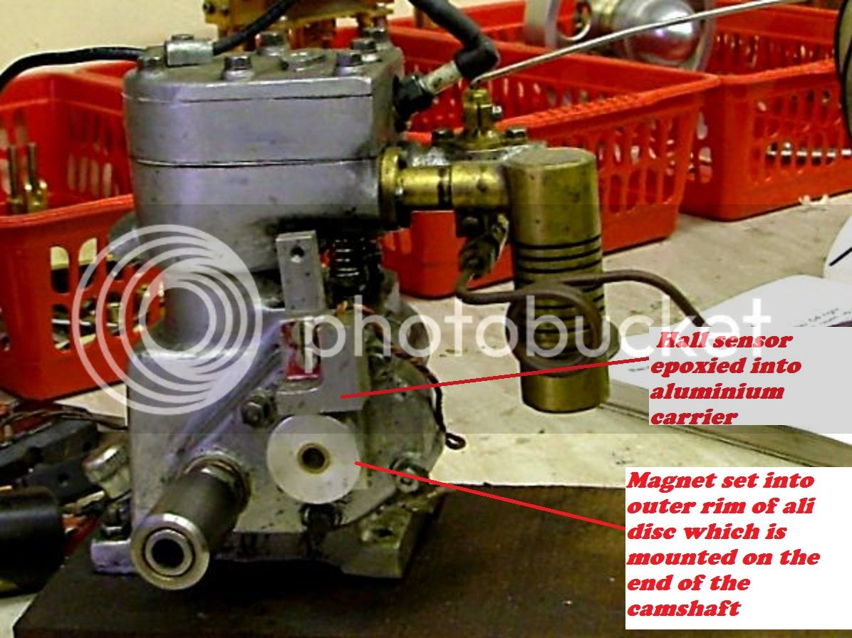
If say you embedded it (them) in the outer rim of say a 3" flywheel, then you would require about 3 x 3mm magnets side by side in a line around the rim to give you enough dwell angle for the hall sensor to be turned on and so to charge up the coil. The reason for this is that the outer surface speed is much faster than the surface speed of say the hub even though they are rotating at the same revs.
I used to mount an ali disc on the end of the camshaft (for single cylinder 4 stroke engines) of around 5/8" to 3/4" diameter with the 3mm (1/8") magnet embedded in the outer rim. This worked perfectly for engines up to around 5,000 rpm. Never made any that ran faster, but I would suggest going down 1/8" or even 1/4" on diameter of the ali disc if the engine runs any faster, this will give a longer dwell angle.

As usual I have an old picture of one I did showing the disc with a hall sensor epoxied into a holder so that it could be advanced and ********.
Please excuse the condition of the engine, it has had a good dose of running in with WD40 added to the fuel.

engine%202_zpsiahkn3fu.jpg


John
 
Willray:

You didn't specify how many cylinders your "old time" engines have but I'll assume single cylinder engines.
It was also tough to weed out your exact question from your post.
But I think what you're wondering is if the default 20ms time out of the ignition circuit will play havoc with a very slow turning (single cylinder) engine such that the spark would occur too quickly because of circuit time-out rather than the points actually opening.
The 20ms time-out may be too short for a SINGLE CYLINDER engine at hand cranking speeds making the spark occur sooner than expected. And, like you said, appear to act like a "super advance" at low rpm's.
The 20ms can be increased by increasing the value of C2. It wouldn't matter if C2 were increased in value to provide something as crazy as one second of time-out. It's just there as a safety circuit to protect the coil.
BUT
Personally I would leave the 20ms time-out as it is. The engine will soon start and be up to a reasonable running speed and a bit of extra advance while cranking should pose no problem.
Don't forget you should adjust the timing of the engine with a timing light and the timing marks of the engine.

Sage

Greetings sir,

I'm down to mostly polluting rather than contributing at this point, but just for completeness:

I'm interested in mostly single, a few 2-cylinder, and occasionally 4-cylinder engines, that generally produce up to around 20HP, with operational speeds typically in the range 600-2200 RPM.

And I apologize for my somewhat rambling writing. You're both plagued by my tendency to write fables rather than technical documentation, and by the fact that I already had about half the answers I wanted. As such I was partly writing just to record some of the thoughts, because I find this to be one of the best-documented online discussions on DIY electronic ignition designs/conversions, and having made some mis-assumptions coming into it from the direction of using it as a "points eliminator" in "real" engines, I figured I might save someone else a headache if I moved some of those assumptions and the corrected thinking into the light of day.

With respect to whether the 20ms timeout is safe, I think I've convinced myself not to find out. Running the numbers more carefully, with where many of my engines try to put the cranking timing, and the average points dwell angle, the 20ms timeout would put the spark dangerously before TDC. Since it's easy enough to push that delay out considerably, and the coil has plenty of thermal mass to occasionally absorb being stuck with the "points closed" for a reasonable fraction of a second, I think I'll save my fingers and push the timeout up to something more like 250ms.

Thanks for all your work on this design!
Will
 
Umm, not to be contrary, but the physics magic is slightly backwards of that... The current builds in the coil and reaches its maximum once the field saturates. Back-EMF is produced by the changing field while the field is building, and this limits the in-rush current. The ballast resistor is there to cap the current through the coil, once the field is saturated and the back-EMF has reduced to zero.
Nothing really contrary in that statement. Once the magnetic field reaches its full strength, the extra current just builds heat, whereas a tiny current can keep the magnetic field from collapsing. The ballast resistor or resistance wire also limits the current inrush as well, increasing the necessary dwell time. This is why it disappeared after the first generation (5 pin) automotive ignition systems.
Depending on who you ask, a typical automotive coil takes on the order of 5ms to reach saturation, maximum current, and therefore maximum stored energy. If the hall sensor in this ignition "sees the magnet" for less time than that, then the spark energy will be affected.
I have no data that states otherwise, but modern automotive coil design has almost certainly pushed that figure down, and overall efficiency up.

Ideally Dsage and Jgedde could design a circuit that could provide power to the coil uniformly 10ms or so before the magnet _leaves_ the hall sensor, but this would require them to either design a psychic circuit that knows that the hall sensor will open in 10ms, even though the hall sensor (at higher RPMs) hasn't closed yet, or, (as far as my circuit design skills allow) would require including a microprocessor to predict when the sensor will next see the magnet based on the last revolution.
Such a design would be far enough removed from this circuits intended purpose that it becomes a bit apples and oranges. He has designed a simple ignition circuit that appears very robust, commendably so in fact.

Neither of those seem particularly likely, or appealing solutions, so it looks like you're left tuning this circuit both with respect to the rotational position of the hall sensor for timing, and with respect to the radial position of the sensor towards or away from the rotating magnet, and the size of the magnet, for dwell.
Both are rather easily implementable solutions for the homebrew IC engine market. :)

The next option would be to switch to a rotating optical slit-disk and optical sensor for the timing detector. Dwell could easily be set in that system by controlling the (arc angle subtended) length of the slits.
Optics are very sensitive to dirt, and the optical shutter disc on the old Mitsubishi 2.6l full size engine could only be produced by photoetching. So unless your very good with your index, and can mill a .015 slot in .010 stainless disc, I would avoid that method. :rolleyes:

There are other ignition systems out there that utilize microprocessors as counters and delay a triggered signal (about 45 btdc) based on rpm maps for variable advance.
 
Nothing really contrary in that statement. Once the magnetic field reaches its full strength, the extra current just builds heat, whereas a tiny current can keep the magnetic field from collapsing. The ballast resistor or resistance wire also limits the current inrush as well, increasing the necessary dwell time. This is why it disappeared after the first generation (5 pin) automotive ignition systems.

I guess I'm still being contrary, or perhaps it's a matter of semantics, but, the magnetic field is directly proportional to the current. As a result, all of the current is necessary to sustain the field. On the other hand, once the magnetic field has stabilized, very little (theoretically none) of the electrical energy dissipated goes into the field, so yes, what energy is being dissipated is going into heat.

(regarding minimum dwell) I have no data that states otherwise, but modern automotive coil design has almost certainly pushed that figure down, and overall efficiency up.

I'm sure some gains in efficiency have been realized, but, a coil ignition is a fairly fundamental resistive/inductive/capacitive circuit, and even antique LRC circuits perform fairly close to their theoretical/idealized optimums. Essentially they're limited in terms of how fast they can store energy in the magnetic field, by the fundamental physics of resistors and inductors, and other than small changes that can be brought about by things like slightly decreased resistance through optimized metallurgy, there's not a bunch that can be done to dramatically change their performance.

In addition to eliminating the need for a distributor, one of the big advantages realized by multi-coil-pack ignitions for modern engines, was that the dwell for each cylinder could be made longer than the duration between successive cylinder firings. This helped eliminate problems with weak spark at high RPM, that could not be overcome by coil optimization with the physically limited dwell duration inherent to single coil designs.

Of course, this is all just idle chatter here, since I'm running engines that, at the most modern, have 1960s ignition components.

Such a design would be far enough removed from this circuits intended purpose that it becomes a bit apples and oranges. He has designed a simple ignition circuit that appears very robust, commendably so in fact.

Absolutely. Which is why I thought it worth extending the discussion to practical aspects of applying the circuit to "real" engines as well as the model engines for which it was designed. It is, as far as I can tell, the nicest, most robust, and most carefully thought-out points-replacement ignition circuit to be found on the internet. It just has some implementation details that need to be considered before use, to eliminate "gotcha"s in real-engine drop-in-replacement applications.

Optics are very sensitive to dirt, and the optical shutter disc on the old Mitsubishi 2.6l full size engine could only be produced by photoetching. So unless your very good with your index, and can mill a .015 slot in .010 stainless disc, I would avoid that method. :roll eyes:

I have no personal experience with trying to implement such a thing (only, amusingly, with that particular ignition ceasing to function), but, I suspect there's a big difference between "could only be produced (to adequate tolerances to make their EFI and spark control computer happy)", and what would be necessary to run an engine that's used to a crappy points ignition, on a crappy worn distributor, better than what the points could do.

Realistically, the tolerances required are no harder to maintain than the tolerances required for the magnet and hall-effect sensor, with the primary difference being that one could adjust the "points closing" timing (which inherently doesn't require much precision) much more easily than can be done with magnets.

The optical-dirty problem does concern me, but maybe I'll make one just for gits and shiggles. Bet I can maintain adequate tolerances to run a 1 or 2 cylinder engine with just a hand-file and jeweler's saw.

Will
 
I guess I'm still being contrary, or perhaps it's a matter of semantics, but, the magnetic field is directly proportional to the current. As a result, all of the current is necessary to sustain the field.

That part is not semantics, it takes very little current to maintain a magnetic field created by a larger current. Modern ignitions have done this ever since the demise of the round oil filled coil.
 
Will et.al.

As with any circuit there were compromises made for simplicity, ease of construction, typical rpm's and cylinder count of model engines. And the ability to energize a coil for at least several times the time it takes to fully energize many of the existing small model coils (which require much more time than a full size car coil BTW). While at the same time being a protection device against continuous activation.
Most model engines idle at more than 1000rpm, are cranked by things like electric drills that run at about that speed and run at several thousand rpm. The 20ms timeout was probably reasonable. But, for a full sized SINGLE cylinder engine that might have a maximum few hundred rpm then by all means do some basic calculation or measurement of the dwell TIME produced by the points at cranking speed (if that's what you want to use) and change C2 to give a longer time-out to suit the application. There is no harm in making the timeout many times longer as long as it still protects your coil. But don't get crazy with it since other circuit values may come in to play and a much larger capacitor may affect the normal operation.

BTW, to address another issue that was pointed out. The apparent intermittent triggering when using low battery voltage and waving a magnet manually over the sensor had nothing to do with the speed of the magnet moving past the sensor per se. It had to do with the small transistor not having enough drive current (with low batteries) to turn it on quickly. The coil was firing in most cases but the transistor was switching too slowly (and hence the field was collapsing too slowly) for the coil to produce it's full output. Hence the resistor R6 was changed to 22k to drive the transistor harder (and faster). But that's all history as long as you use the most current schematic values and it works ok now with weak dry cells of 6v and a full sized car coil.


Sage
 
That part is not semantics, it takes very little current to maintain a magnetic field created by a larger current. Modern ignitions have done this ever since the demise of the round oil filled coil.

Nope, that's not semantics, and I apologize for pointing it out, but modern ignition or not, you can't beat Ampere's law. The magnetic field is not something that gets "built up" by a big current, and then "kept trapped" in the coil by a small current. The current is why the field is there, and the field exists because, and only because, the current is flowing, with the magnitude of the current dictating the magnitude of the field. Reduce the current and the magnetic field collapses. This is why coils work, and it's simple physics.

At this point this has gotten wildly off the topic of this wonderful circuit, and I'll bow out here, both because it's off topic, and because you're not arguing with me, you're arguing with almost 200 years of extremely-well characterized physics.

Will
 
Will et.al.

As with any circuit there were compromises made for simplicity, ease of construction, typical rpm's and cylinder count of model engines. And the ability to energize a coil for at least several times the time it takes to fully energize many of the existing small model coils (which require much more time than a full size car coil BTW). While at the same time being a protection device against continuous activation.
Most model engines idle at more than 1000rpm, are cranked by things like electric drills that run at about that speed and run at several thousand rpm.

...

Sage

Thank you sir. These are exactly the kind of considerations that I hadn't, umm, considered, when I first started thinking about using your circuit as a way of improving the ignition reliability on my assortment of antique rust.

I really do appreciate all the work that you and Jgedde have done on this circuit, and now that I understand the practical considerations of applying it to real engines, I think it'll be immensely valuable for my rust collection, as well as to others who collect and restore rust.

Someday, maybe I'll have the time to get my shop in order, and get around to making a model engine or two, too. It's on my list for when I finally get the new shop finished.

I do think I'll make an optically-triggered version of your circuit just as a joke. A bit of digging says that both Panasonic and Omron make nice slot sensors with dark-on outputs, which will make adjusting the timing pretty easy. I'm thinking I can get perfectly adequate timing control out of a scrap from a soda can, and tin-snips ;)
 
Will:

Re: >>> Omron make nice slot sensors with dark-on outputs,

Not sure exactly how you are going to arrange the mentioned sensor but, as with the Hall sensors and original ignition points you will need the input to our ignition circuit to be normally High (i.e. 12v) and then drop low for several milliseconds (at least) and then go back high again until the next spark is required.
It may actually work in reverse but you would be racing the timeout circuit every time if the input was normally low.

Sage

Yup - that's doable with the slot photo-sensor. Hooked up properly they're much like a hall sensor, with an output that sinks current to ground when "on", and that floats when "off". Give it a pull-up resistor, and it should be good to go.

With a Dark-on output, the trigger can be just a flying tab, with a leading edge "wherever", so long as it provides adequate dwell, and the trailing edge at the intended "points opening" trigger point. I can't see any reason that the tab can't be simply attached to the outside of the flywheel - any reason other than safety at least, but for a proof of concept it should do. Easy peasy.

Will
 
I ended up changing the 1 uF capacitor in my circuit to 6.8 uF. This increased the lock-out inhibit time and makes the delay much more obvious along with when the plug will fire under normal conditions. 6.8 uF is a standard value but is less common. That said, a 4.7 uF capacitor would be a reasonable choice as well and much easier to get. Most 4.7uF caps you can readily get will be polarized. IN this circuit, the (-) pin goes to the hall sensor input side.

Cheers!
John

So, can anyone give me rough numbers on how much the timeout changes, going to, say 4.7, 6.8, or 10uF? Alternatively, roughly how much capacitance would you estimate would be needed, to push the timeout up into the 100+ms range?

Thanks,
Will
 
It'll probably be close to doubling if you double the capacitance. It's 1uf for 20ms now (I think) so 5x that or 5uf should get you close to 100ms. But that's only rough figuring. Trial and error would be the best approach But don't go crazy with it. Like I said before other issues may arise.
Also heed the advise about polarity of the capacitor (quoted above).

John has a spice simulation of the circuit and can probably tell you better what's required for 100ms.

You really need to do the math (or measurements) on how long your points are actually closed at cranking speed if you are worried about artificial advance. You might be surprised how fast you are actually flipping it past TDC by hand or foot or whatever you're planning. The points may not actually be closed very long. I wouldn't get too paranoid about a bit of advance. And don't forget you can adjust the timing (usually).

Sage
 
It'll probably be close to doubling if you double the capacitance. It's 1uf for 20ms now (I think) so 5x that or 5uf should get you close to 100ms. But that's only rough figuring. Trial and error would be the best approach But don't go crazy with it. Like I said before other issues may arise.
Also heed the advise about polarity of the capacitor (quoted above).

Excellent. I wasn't sure the timeout was likely to roughly scale with the capacitance, and didn't want to poke around blindly.

I'll just grab some film caps in roughly the right range, and we'll see what we see.

John has a spice simulation of the circuit and can probably tell you better what's required for 100ms.

You mean there's someone else out there who's obsessive-compulsive enough to build simulations for trivialities? I'm pretty sure this is some kind of disease...

You really need to do the math (or measurements) on how long your points are actually closed at cranking speed if you are worried about artificial advance. You might be surprised how fast you are actually flipping it past TDC by hand or foot or whatever you're planning. The points may not actually be closed very long. I wouldn't get too paranoid about a bit of advance. And don't forget you can adjust the timing (usually).
Sage

I get the feeling you've never been holding the crank of a 20HP engine when it kicks back :)

It's true I haven't measured (when I get a chance, I will do so and report back), but based on the cam profile, on some of my engines the points are closed for well over 180deg of crankshaft rotation. I estimate I hit about 1 revolution per second hand-cranking, maybe even 2 or 3, but that still leaves the points closed for an awfully long time!

Don't worry, I'll figure it out.
 
...
Don't worry, I'll figure it out.

Ok, I'm back with some data. Been working pretty much non-stop on the framing for our new shop, so I haven't torn into any of the engines to get real-live points-dwell times, but I did scare up a batch of caps and test the circuit timeout with a handful of the likely suspects:

C2 value :: dwell time before timeout

1uF :: 18ms
1.5uF :: 28ms
2.2uF :: 40ms
2.7uF :: 55ms
3.3uF :: 60ms
4.7uF :: 85ms
5.6uF :: 95ms
6.8uF :: 120ms
8.2uF :: 140ms

Not quite linear (and of course, these were +/- 10% caps), but close enough.

As a side note, just in case this saves anyone else hair-pulling, don't try to test this thing with a soft power supply, and expect anything resembling useful numbers or performance. I recently "upgraded" one of my bench supplies in the lab, and stupidly used the new one while testing this circuit. Unfortunately the new one apparently doesn't react to changing load conditions particularly well, and the output droops precipitously before the regulation catches up and stabilizes things when presented with a suddenly increased load. Undoubtedly the result of new modern digital wizardry and optimization (nor did it flag an overcurrent condition, which at least would have been acceptable. BAD HAMEG!). The results, with a low-ohm load in place of the coil, were between confusing and useless.

Will
 

Latest posts

Back
Top