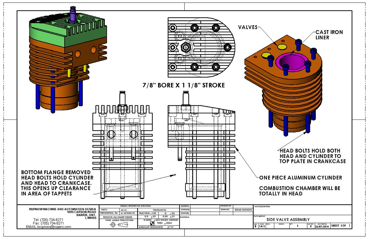
My heart rate and blood pressure have returned to normal, now that I am completely finished with my version of the Nemett Jaguar. I don't WANT to build anything else until fall.
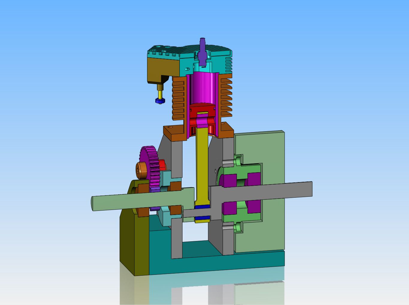
Then I want to build a totally new engine that is not a modified version of some one else's design. Oh, it will still have all the standard things, --piston, con rod, crankshaft---you get the idea.
---I am very interested in the gearless engines, just because of how different they are. I have also learned from Malcolm Stride and whoever (Mr. Webster, I assume) designed the Webster engine. I really like that cantilevered crankshaft design as used in the Lynx and the Webster--it so greatly simplifys the crankshaft manufacturing. There is also the big plus that with a gearless type engine and an "atmospheric" intake valve, no camshaft or camshaft bearings are required.
I won't build another engine with a wet sump and splash oiling, because it is simply too difficult to keep track of the oil level once the sump is all buttoned up. I have been doing some research, and in addition to "sealed for life" ball bearings, one can also purchase "sealed for life " needle roller bearings and sleeves. In my mind, these would be almost perfect--sealed ball bearings for the crankshaft and sealed needle roller bearings for the big and little ends of the con rod.
I probably won't try and use cast iron rings again. I have proven to myself that yes, I can make them, but it is a very "chancy" operation, and even when working at their best, they don't give the compression that a Viton o-ring does.
I have proven to myself that old style points type ignition is both cheaper and far less susceptible to damage than the new electronic ignitions, but they are bulky and take up a lot of room compared to a magnet and pick-up, so the jury is still out on which I will use.
--I like the hit and miss style of engines, because there is a bit more neat mechanism available to see operating, and the real big plus is that these engines run extremely cool because of the fact that when in "miss" cycle they constantly circulate room temperature air thru the cylinder which keeps it cool.
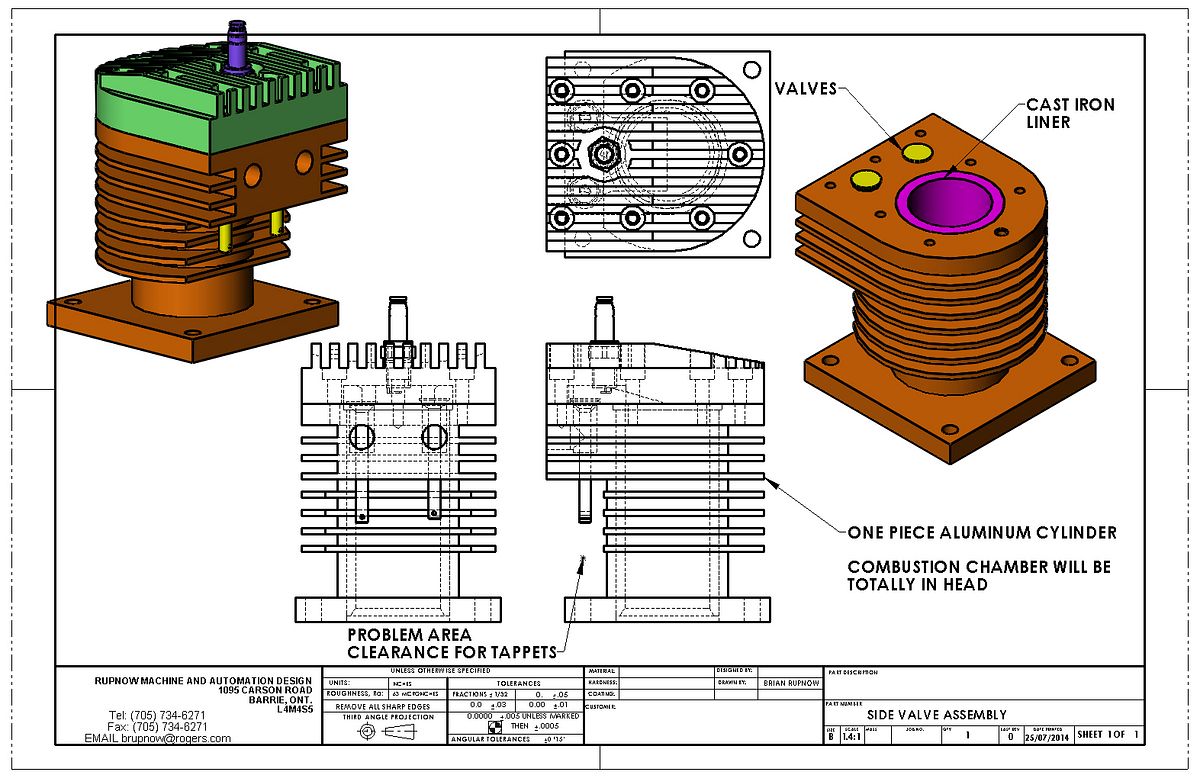
--I would use a cast iron cylinder, and possibly a cast iron piston, as this will be a slow revving engine so the inertial weight of the piston won't be that big a deal.
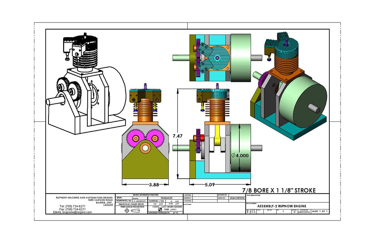
---After designing and building the "Rupnow Engine" and seeing that it wants to levitate at any speed above 50 RPM I will definitely find a way to balance the crankshaft with bolt on weights.
That all for now. If any of you fellows know of any real nifty "gearless" mechanisms, please let me know. I have plans here for the Philip Duclos style gearless engine, also for the old "star wheel" type as seen on full size hit and miss engines, and the nifty one that Myrickman posted on Modelenginemaker forum. I would be interested in any other gearless designs that I am not aware of.----------------Brian rupnow
Last edited:


